
zeiss rotary table free sample
You have already attended a ZEISS CALYPSO Basic Classroom Training or you have already gained practical experience and would now like to deepen your knowledge.You can find further information on our classroom training courses here.
ZEISS eLearnings give you the freedom and flexibility to expand your knowledge of measurement technology - at your own pace. To access the training you have purchased, log in to the ZEISS Metrology Portal. In the Academy Metrology area, you will find all the training courses you have booked under eLearnings. These are available for twelve months from the start. ZEISS eLearnings are interactive and can consist of video tutorials, software simulations and numerous practical excercises. At the end of the training, you will take a test and receive a certificate upon successful completion.

The ZEISS Automation Interface allows you to easily automate your measuring device without any engineering effort. In addition to starting inspection plans and providing feedback on measurement results or machine status, the application allows you to control CMM peripherals. The interface is also preconfigured for all products in the ZEISS Integration Series. For example, the control of automatic fixtures or the pallet feed can be configured effortlessly with just a few clicks. Individual fixtures developed by you can also be controlled via configuration.
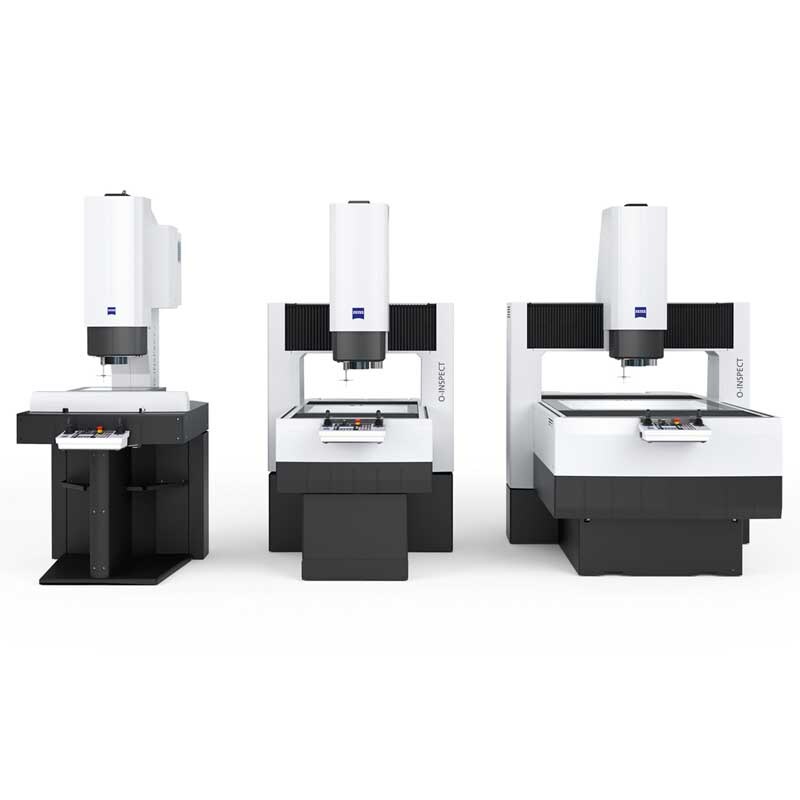
ZEISS O-INSPECT doesn’t skimp on when it comes to software, because with ZEISS CALYPSO you use our universal measuring software that is also used on portal measuring machines such as ZEISS CONTURA.
ZEISS CALYPSO impresses with its intuitive operating concept that combines functional diversity and flexibility. Programming is performed by clicking on the desired measuring elements on the CAD model with the mouse or even more simply by probing, regardless of the sensor, and automatic measuring element recognition.
Various software options offer the right tools for special requirements, such as the standard curve functionality of the O-INSPECT or the integrated measurement report software tool ZEISS PiWeb reporting.
ZEISS FutureFit allows you to retrofit many additional functions. This keeps your processes cost-effective and reliable. With ZEISS FutureFit, the CMM control (C99 types) is brought up to the current series status, thus enabling simplified and efficient service. It also serves as a basis for software maintenance contracts and extended software functions and enables you to use current and future software versions.

I"m looking for some assistance. Attached a picture for reference. The part I am trying to inspect has pockets 120 degrees apart. Using the rotary table I can get the part rotated 120 degrees to inspect the planes. But the probe is not going into the pocket to scan the plane. It is colliding on the edge of the part. Now if try to change the degrees to compensate (125degrees to 120 degrees) the probe will go into the pocket but drive well past the plane. I have been going at it for a few days and have come up empty.
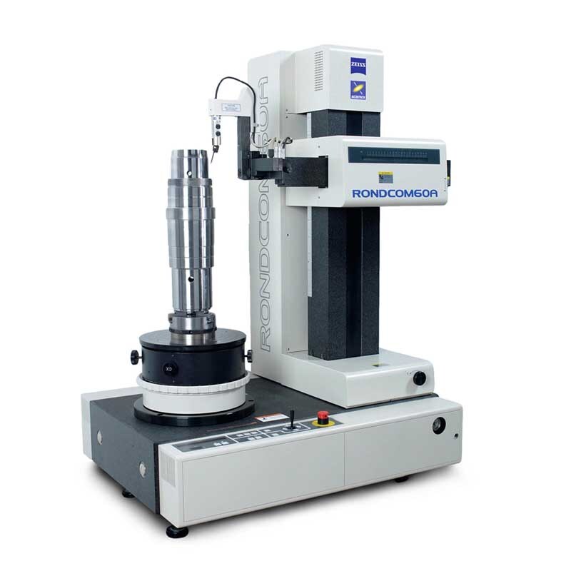
Details:High throughput thanks to fast, automatic alignment in less than 60 seconds (CNC) Long-term stability thanks to the high-quality granite construction of all axes Precision air bearings in all axes Ultra-accurate, wear-free rotary table on air bearings IMR sensor with safety function in all axes for maximum protection of the stylus Incremental glass scale in the R axial direction
The object of the present invention is to provide a coordinate measuring device that makes possible, in an operation involving manually guided scanning with rigid probes, a measurement accuracy of a few μm without any special demands on the operator. In addition, the device is to be of simple construction, easy to operate and suitable for the measurement of geometric elements aligned in different directions.
This object is achieved by means of a coordinate measuring device according to the invention, having a probe mounted by means of a plurality of rotary shafts arranged one behind the other to be easily movable in several degrees of freedom and a workpiece table that is rotatable and tiltable about at least two shafts.
Using the new coordinate measuring device according to the invention, a large number of measurement points can be very quickly sensed with good accuracy. The alignment of the axes of symmetry of the geometric elements with the probe axis takes place quickly and simply by means of the rotatable and tiltable workpiece table. The table has centering elements that can be determined by means of the probe alone, without further or additional measuring means.
The carrier (4) is U-shaped in side view. The two shanks of the "U" contain bearings for a vertical shaft (6), by means of which a first lever member (5) can be pivoted horizontally. The rotary motion is sensed by a graduated circle (16) fixed to the shaft and a photoelectric transducer system (15). A second lever member (7) is mounted, likewise rotatably, at the end of the lever member (5) by means of a second shaft (8), which is parallel to the vertical shaft (6). A graduated circle (18) in combination with a reading head (17) is used to sense the rotary motion of this second rotary shaft (8). The two rotary shafts (6) and (8) are spaced apart and are aligned approximately vertically.
The movable members (5, 7, and 10) are composed of carbon fiber reinforced plastic (CFRP) or invar and hence have a very small mass, with a highly stable structure. At the same time they possess insensitivity to temperature effects.
The two shanks of the fork-shaped base (1) of the device contain bearings (39a, 39b) for a horizontal tilt shaft (19), which serves as a mounting for a carrier (20) for the workpiece table. A clamping plate (21) of the workpiece table is mounted to be rotatable about a shaft (29), in the carrier (20) and at right angles to the horizontal tilt shaft (19). A workpiece (22) clamped to the rotary tilting table constructed in this manner can be aligned in space in different positions, such that the various geometric elements to be measured by scanning are aligned with the probe axis. In order to ensure the alignment of the workpiece in all possible spatial directions, a third shaft can be provided that has a pivot axis that is aligned perpendicular to the shafts (19) and (29). This pivot axis also can be integrated into a mounting plate on which the workpiece is clamped outside the device, and which is then fastened with the workpiece to the rotary tilting table.
For example, for scanning the bore (30), the workpiece table is tilted into the position shown by broken lines, in which the axis of symmetry of the bore is aligned parallel to the long axis of the probe (11). The probe ball (12) can then be made to travel along the inner wall of the bore in constant contact with the inner wall without the probe shaft striking the wall.
The rotary tilting table (20, 21) is constructed of molded ceramic parts, which have high stability and load-carrying capacity and low thermal sensitivity.
The rotatable clamping plate (21) of the workpiece table forms straight line edges with the lower part (20) of the table and carries V-shaped grooves (31) on all four end faces. These grooves can be sensed and traveled by the probe ball (12) or by one of smaller diameter (12a), see FIG. 2a, for determining the workpiece position.
The tilt position of the table (20) can be determined when the table is tilted forwards through a relatively large angle of up to 90°. For this purpose, a pair of grooves (32) are located on the rear side of the table (20) and are easily reached by the probe (11) in the tilted position of the table.
The workpiece (22) is first aligned by means of the rotary tilting table with respect to its geometric elements to be measured--in this case, for example, the bore (30)--such that the bore axis is aligned approximately parallel to the long axis of the probe. For this purpose, the rotary tilting table is brought into the position shown by broken lines in FIG. 1. In this position the shafts (19) and (29) of the table are clamped by means of devices that are not illustrated in detail.
If additional geometrical elements that lie in other planes or on other sides of the workpiece are to be measured in relation to the bore (30), the spatial position of the rotary tilting table is then determined. For this purpose, the probe ball (12) is guided in the grooves on the clamping table (21) along at least two directions or at least two sides. The computer (26) determines from the two measured straight lines the spatial position of the plate (21) and hence of the workpiece (22).
The workpiece position is then changed by means of the rotary tilting table such that the probe (11) is perpendicular to the next measurement plane or parallel to the next bore axis. The altered position of the plate (21) is then determined anew, as described herein above. Linking up the workpiece coordinate systems in the differently tilted or rotated positions is thus ensured. This is accomplished without excessive expense for reproducibility or precise mounting of the two shafts (19) and (29) of the rotary tilting table and without additional measuring systems for determining shaft positions.


 8613371530291