
accumulating rotary table free sample
Equipment Snapshot: Multi-Conveyor recently built both an unscrambling rotary table and an accumulation rotary table which are connected by a 30’ basic plastic straight running chain conveyor in this semi-automated conveyance application.
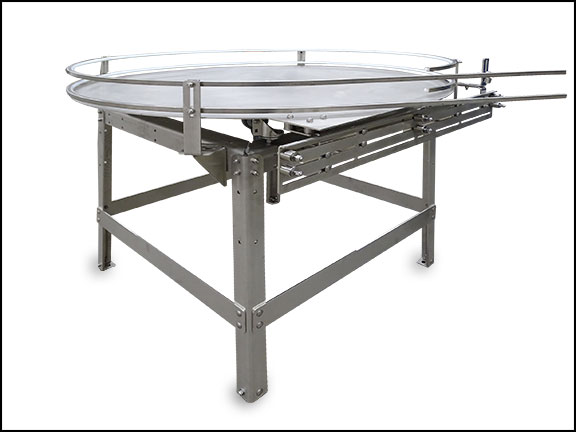
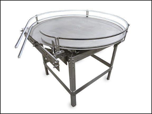
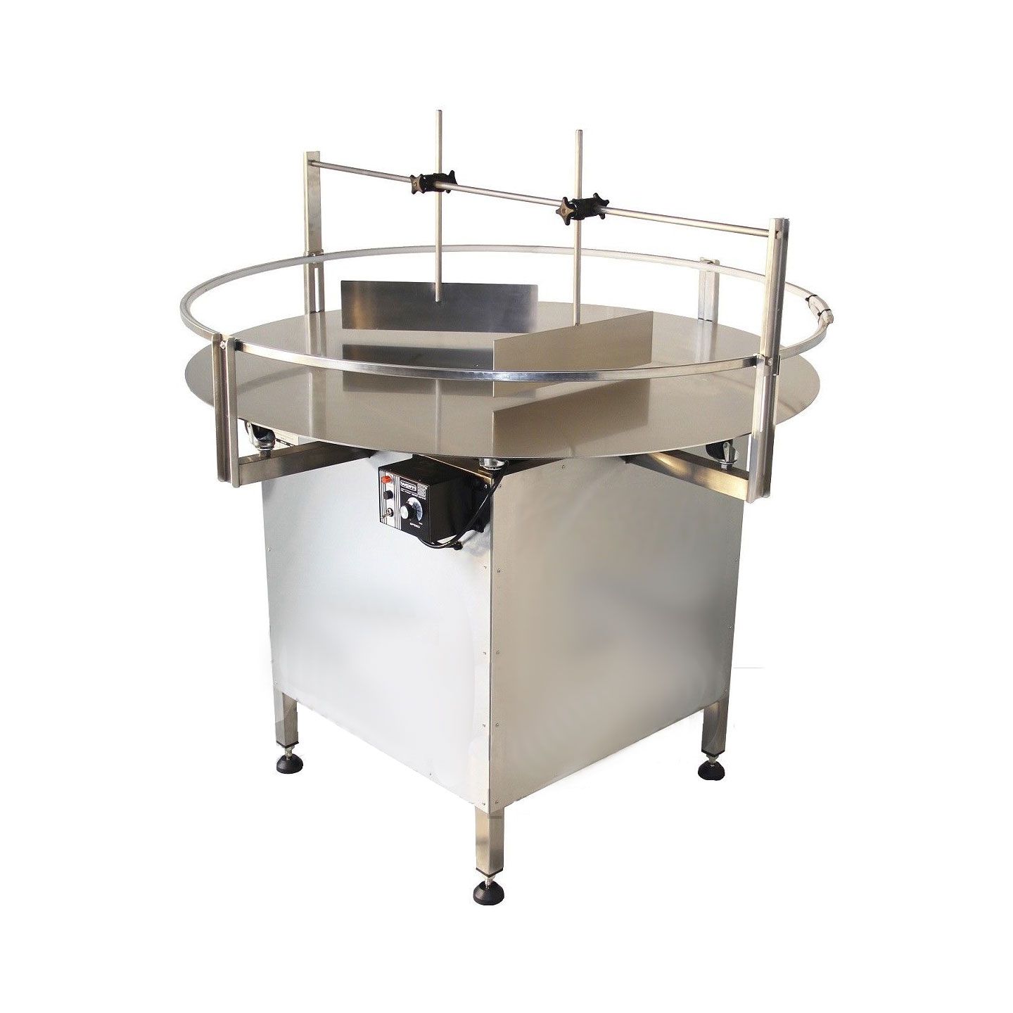
The first mild-steel constructed rotary accepts bulk, random hand-loaded glass containers that sweep through two deflector arms. These flexible arms gently control the cluster of individual products into single file, then onto the mat top conveyor chain.
During the 30’ straight chain, labels are applied by the customer’s press-on labeler (not shown) before discharging onto the accumulation table where an attached staging shelf assists manual hand-packing into cases.
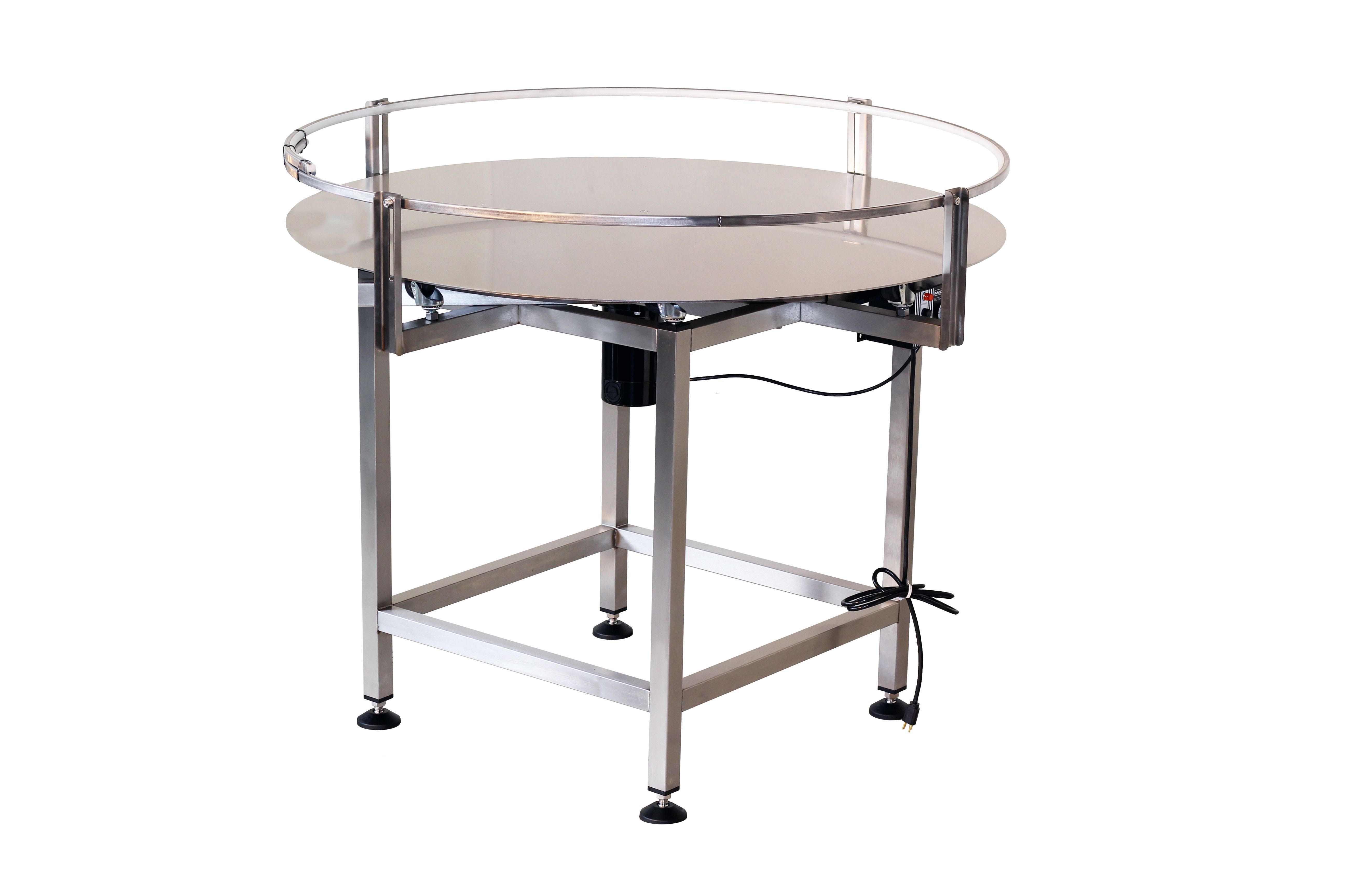
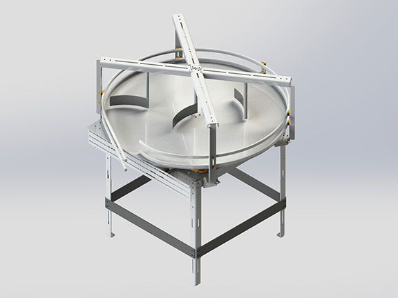
Stainless steel rotary top discs feed the guided, seamless transfers that are positioned at both the unscrambler discharge and accumulation table entrance.
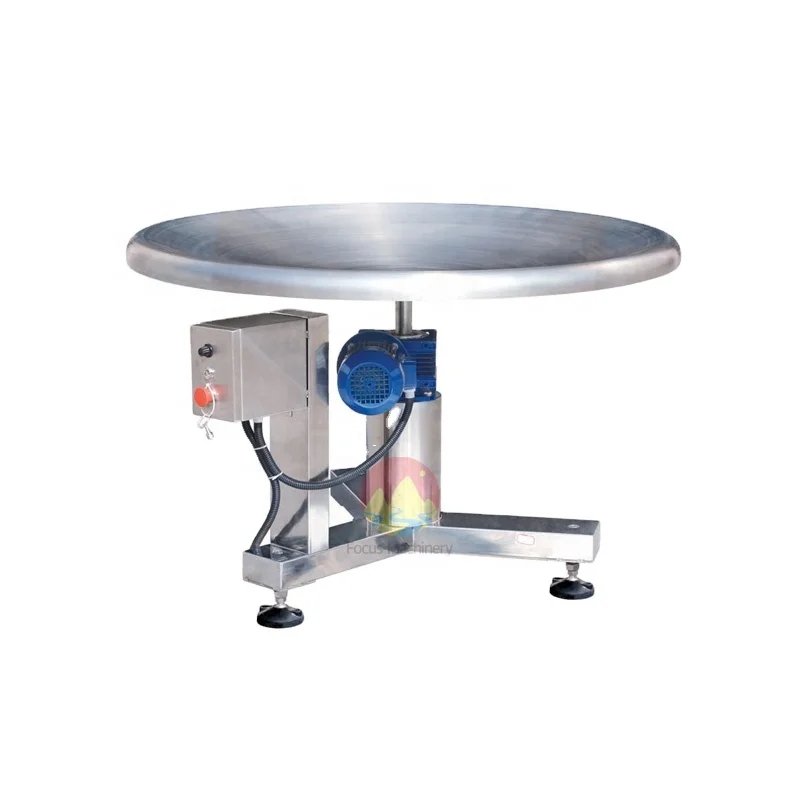
Unscramble style rotaries are a simple, cost-effective way to transfer bulk product to one-lane single-file conveyance. Rotary accumulation tables are supplied with an enclosed cabinet and typically variable speed controls, using either DC or VFD controllers. Multi-Conveyor’s standard rotary table sizes are 36”, 48” and 60” diameter. Custom sizes are reviewed upon request.

Alibaba.com offers 310 rotary accumulation table products. About 62% % of these are other packaging machines, 4%% are other machine tools accessories, and 3%% are table.
A wide variety of rotary accumulation table options are available to you, such as wood, plastic and glass.You can also choose from food & beverage factory, manufacturing plant and food shop rotary accumulation table,As well as from automatic, semi-automatic rotary accumulation table. and whether rotary accumulation table is 1 year, 6 months, or 1.5 years.
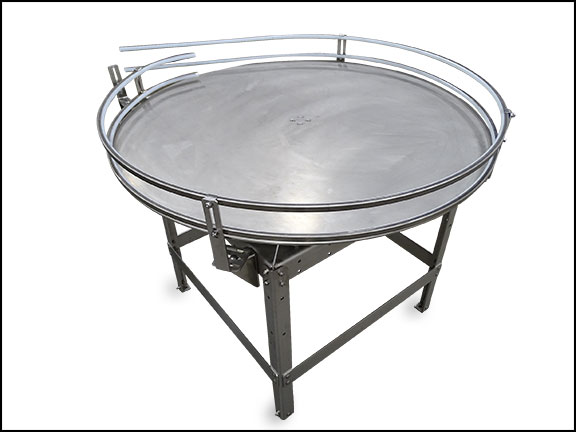
SNEED-PACK Rotary Tables can be used to unscramble product and feed a conveyor, also as a buffer space to accumulate product until the downstream conveyor is ready for additional product or collect. Accumulating rotary tables are designed to collect filled containers from a filling line to prevent slowdowns by quickly removing the finished product from the conveyors during operation. Can be set for clockwise and counterclockwise rotation.
Infeed Table - for easy input of product at the beginning of the conveyor. Alternately, it can be used at the end of the conveyor as a work table for an operator that is pulling and packing finished products.
Infeed Table & Unscrambler - ideal for beginning of the line to feed and unscramble product to input onto the conveyor. Recommended accessory: Transfer Plate & Gate
Our SNEED-PACK Rotary Accumulation tables can be used at the end of production lines, as an infeed to a conveyor, and as a buffer space to accumulate product until the downstream conveyor is ready for additional product or collect. Rotary accumulation tables are designed to collect filled containers from a filling line to prevent slowdowns by quickly removing the finished product from the conveyors during operation. Can be set for clockwise and counterclockwise rotation.
Rotary Work Tables were designed to accept product flow from discharging belt or other general material handling systems. The rotary table or some times called spinning table is a robust design, which is engineered to take demanding punishment from an industrial environment. The rotary table is the key component in designing a flexible work cell for jobs requiring manual inspection, degating, assembly or packing. In typical applications, the product is conveyed on to a the table to allow multiple operators can efficiently handle tasks or allows multiple products (sub-assemblies) to be conveyed from multiple machines to one location and have one operator handle multiple tasks without added effort or ergonomic strain.
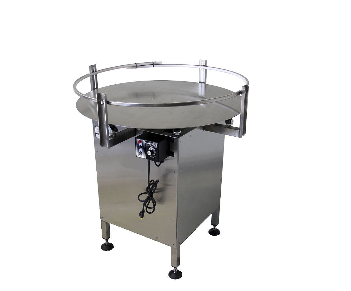
Rotary accumulation tables or unscrambling tables are designed to support a variety of conveyor system requirements. Designed for a small footprint these accumulation tables are often used with round containers such as bottles to accumulate bulk or unscramble bulk products so that they can be discharged in a single file line. An efficient process to balance production rates, a buffer space accumulates product allowing production to continue while downstream product is temporarily stopped.
Rotary accumulation tables are also ideal for hand packing stations or feeding and loading tables. Quality stainless steel components are easy to clean and result in a low maintenance, durable piece of conveyor equipment. Simply install a rotary table between your infeed and discharge conveyor to cost effectively manage your product throughput.
The adjustable supports level the rotary accumulation table on uneven floors to keep the accumulation table stable, seamlessly integrating into current production lines.
Variable Frequency Drive (VFD) speed control sets the optimum table rotation speed, maintaining production schedules and decreasing downtime. MCE’s rotary accumulation table is designed to handle bulk accumulation with ease reducing wear and tear on the motor that can otherwise lead to early motor burnout.
Rotary Tables are manufactured from grade 304 stainless steel with a food-grade nylon top which makes them suitable for food environments or within pack houses.
We manufacture some of the best value rotary tables in the UK, this proven product can be found in use within the supply chain of the major supermarket packhouses.
The main structure of the rotary table is manufactured from grade 304 stainless steel and the top from food-grade nylon. Stainless steel tops are also available.
From a single packing table to full assembly cell layouts, our assembly bench and automation products are reliable, aesthetically pleasing and designed to be reliable, maintenance-free and cost-effective.
Rotary tables are used in a wide range of industries, we regularly work with breweries, health supplement suppliers, food and drink manufacturers, and warehousing and logistics companies to improve their packing flow.
A rotary accumulation table installed in a bottle packaging line for example allows operators to fill the table with empty bottles to feed bottles onto a conveyor in a single line, or have an outlet for finished products to accumulate ready for packing.
Rotary accumulation tables are often fitted with unscramblers and in-feed tables. The unscrambler pushes containers to the edge of the table, whilst the in-feed table allows for larger volumes of containers to be fed onto the rotary table at once.
In-feed tables are a popular option for end-of-the-line accumulation tables because they enable operators to easily remove finished products from the rotary table.
We have many years of experience in building custom rotary packing tables for UK businesses. Our Rotary Tables are used by supermarket suppliers and household names as we offer the most competitively priced fully bespoke rotary tables on the market.
PRECISION ROTARY TABLE Filed July 14, 1969 2 Sheets-Sheet 2 INVENTOR 17/?771? ED515727 ATTORNEY United States Patent 3,615,068 PRECISION RUTARY TABLE Arthur Edelstein, Jamaica, N.Y., assignor to Ardel Instrument Co., Inc., Jamaica, N.Y. Filed July 14, 1969, Ser. No. 841,417 Int. Cl. A47b 95/00, 91/00 US. Cl. 248-349 17 Claims ABSTRACT OF THE DISCLOSURE A precision rotary table for use in electro-optical research includes a stationary base member and a movable support part operatively connected to the base member and rotatable relative thereto. Precise positioning of the movable part in response to actuation of a manually operated means is effected by employing gearing mechanism in which the various rotating parts are continuously subjected to a constant force in a direction such that the meshing gears are placed in back-lash-free engagement with each other. An attachment device may be rotatably connected to the movable part, that device including mechanism which permits quick movement of the attachment device between two preselected positions.
A wide variety of rotary tables are currently used for research purposes. These tables are employed to rotate prisms, crystals, pol-arizers and the like to desired rotative positions. It is imperative in most applications that such positioning be carried out with great precision. Furthermore, it is extremely important that the rotary table be capable of repeatedly positioning the device with the same precision. Unfortunately, manufacturing tolerances which occur in the normal manufacture of the several movable parts in a rotary table render it virtually impossible to achieve a positioning :accuracy of better than a certain lower limit. Thus, far, increased accuracy in rotary tables of this type have been attempted by careful manufacture of the various parts, but even parts made by special techniques still include variations in dimensions which adversely affect the preciseness with which the device can be operated.
The subject invention provides a solution to the aforementioned difficulties by the inclusion of a means so positioned and structured that the various rotating parts in a rotary table are held under constant pressure in close contact with each other. In this manner, lost motion between the rotating parts is prevented and the accuracy of the rotary table is greatly increased.
Broadly, the rotary table of the invention comprises a stationary base member, a ring-like support part operatively connected to the base member and rotatable relative thereto, first means operatively connected to the support part for rotating the part, and means effective to continuously force the first means into a tight engagement with the support part during the operation of the device so that lost motion between these rotating members is prevented.
In one embodiment of the invention, the first means includes a pinion which is mounted on a shaft carried in bearings. The pinion meshes with a gear which is integrally secured to the support part and drives the part through the gear engagement. In the preferred embodiment a driving means for rotating the first means is included and comprises a worm afiixed to a second shaft and a worm wheel secured to the pinion shaft in a position to mesh with the worm. A manually rotatable means such as a knurled knob is secured at one end of the second 3,615,068 Patented Oct. 26, 1971 "ice shaft so that motion of the rotating components may be manually effected.
If properly located, the resilient member may provide still another force component along the axis of the pinion shaft. In the preferred embodiment this is accomplished by wedging the resilient member between a shoulder on the bearing and a flange on the base member, both the shoulder and flange being extended substantially laterally relative to the "aXis of the shaft and being spaced from one another substantially axially of the shaft. With this construction, the worm wheel and the pinion are axially positioned relative to their respective mating gears due to the resilient member being compressed axially in the space. In order to ensure the permanency of the gear location during the operation of the rotary table, the lower portion of the pinion shaft engages a non-resilient device such as a washer or the like, which rests on the base member. Still another resilient member may be placed below the lower bearing in order to provide a further radial force to the shaft so that additional radial pressure on the pinion and worm wheel may be provided.
Because a high degree of accuracy is desired, the manually rotatable means in the preferred embodiment is turned only one revolution for every arc degree traversed by the circular part. With this arrangement, the position of the circular part may be monitored at intervals of one are minute. However, it will be appreciated that with such a fine accuracy the manually operated means must be rotated many times for the circular part to traverse any considerable distance. Thus, if it is desired to rotate the table 90 turns will be required. Many times during the use of a rotary table such as in polarizer experiments, a particular angle must be repeatedly traversed. A rotary attachment device is therefore provided to enable the operator of the rotary table to repeatedly traverse a large distance in a short period of time. The attachment device is preferably mounted on the previously described rotatable part. It includes a lower element which is secured to the rotatable part and an upper element rotatably mounted on the lower element. The upper element functions as a rotary table itself once the attachment device is mounted in position, that is, it carries an optical device to a position along the arc of the circle over which the upper element is moved. Positive stops may be provided on the stationary base member and on the lower element of the attachment device between which the upper element of the attachment device is freely movable, thus providing for rapid but accurate positioning of that upper element in either of two predetermined positions. The rotative spacing between those positions can be accurately adjusted and varied by rotating the rotatable part of the device proper, which carries the lower element of the attachment device.
To the accomplishment of the above, and to such other objects as may hereinafter appear, the present invention relates to the construction of a rotary table device as defined in the appended claims, and as described in this specification, taken together with the accompanying drawings, in which:
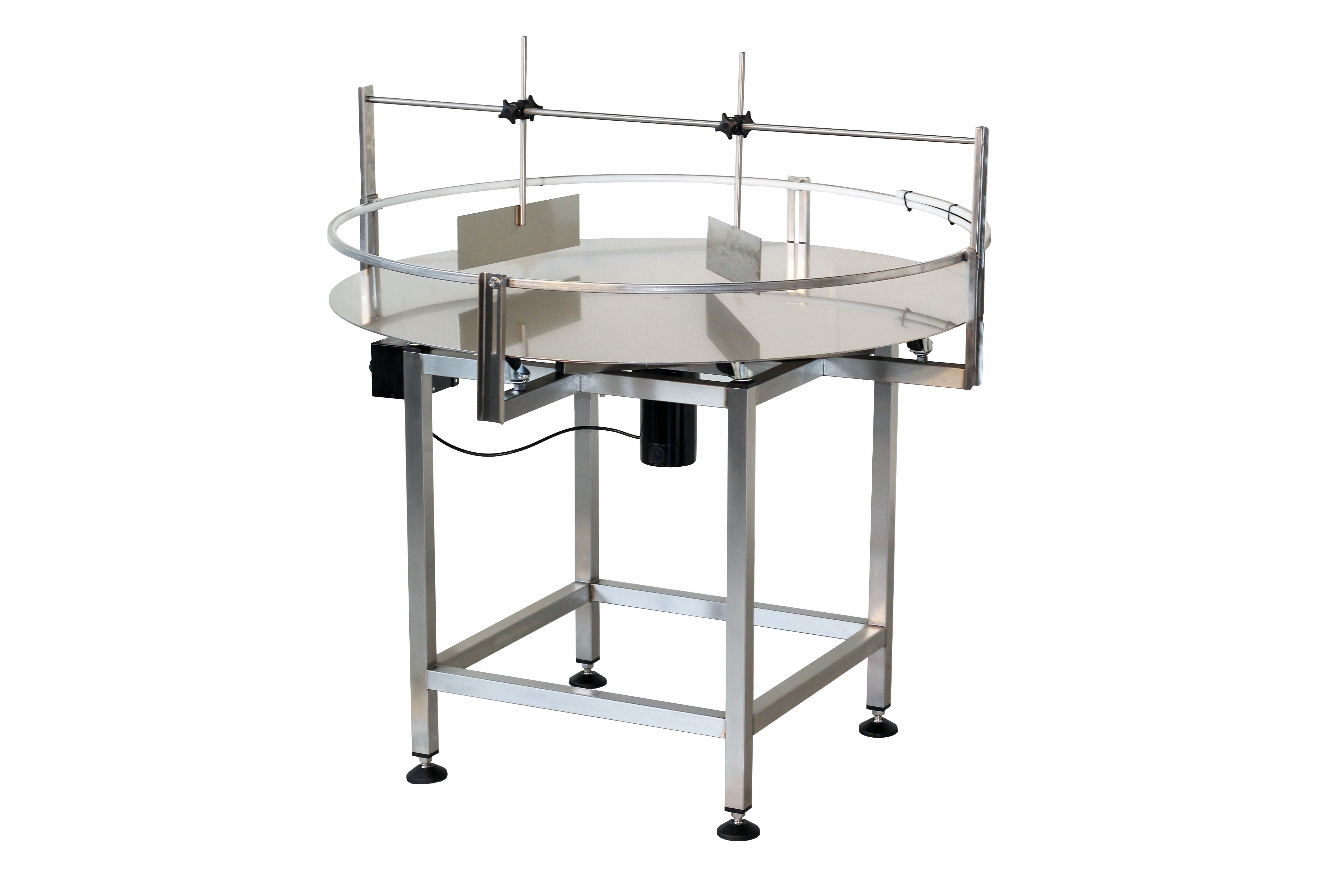
Referring to FIG. 1, a rotary table is designated generally by the numeral or frame 10. The table 10 includes a base member -12 and a cover 14 secured to the base member by means of bolts 16. A ring-like support part 18 (on which the optical device or the like is adapted to be mounted) is rotatably positioned in one area of the cover 14, and includes a series of markings 20 which indicate in degrees the circumferential position of the support part 18. For this purpose an index pin -22 is mounted in the cover 14 and positioned adjacent the markings 20 .on the part 1-8. The cover "14 is also provided with a plurality of holes 24, continuing into base member 12, which may be used for mounting the table to a support. Holes 27 in the part 18 may be used for mounting other devices to hold prisms, crystals and other optical components. A large opening 25 is also provided in the central portion of part .18 so that the optical component may be rotated on its axis, that is, sothat light may enter from below the optical component. A manually rotatable member generally designated 26 includes a knurled knob section 28 and a section 30" which is provided with a plurality of index marks. The section 30 is positioned adjacent a bushing 32 fixed in base member 12 which is also provided with index marks. As illustrated more clearly in FIG. 2, the member 26 is spaced from the bushing 32 as shown at 34 and is rotatable relative thereto. In the actual operation of the device, the part 18 is driven in rotation by the rotation of the member 26. An indication of the specific amount of movement is obtained by reading the position of part 18 at the markings 20 and the position of the markings on section 30, the latter constituting a Vernier or fine indication and the former constituting a coarse indication.
The coupling mechanism between the manually rotatable member 26 and the part 18 is more clearly illustrated in FIG. 2. As there shown, the member 26 is tightly connected to a shaft 36 by means of a screw 38. The connection between member 26 and the shaft 36 is a rigid one since it is highly desirable that there be no motion between these parts when the member 26 is rotated. Worm 40 is pinned to shaft 36, and is constrained axially of the shaft 36 by spring washer 41. Worm 40 in turn meshes with worm wheel 42. The worm wheel 42 is mounted on a shaft 44 (see FIG. 4). The pinion gear 46 is also securely mounted on shaft 44 directly above the worm wheel 42. The ring-like part 18 is integrally formed with a gear 48, which meshes with and is driven by the pinion 46.
It has been determined that a preferred gear reduction ratio between the part 18 and the manually rotatable member is in the order of 360:1. In one embodiment, the gear ratio between gear 48 and the pinion 46 may be 12:1, while the ratio between the worm wheel 42 and the worm 40 is approximately 30:1. With this high ratio, one turn of the member 26 will move the circular part 18 only one arc degree. The index marks on the section 30 of the member 26 can therefore be graduated to increments of as low as one are minute, which is lower than most precise devices currently in use.
FIGS. 6 through 8 illustrate a rotary attachment device 86 which may be mounted on the rotary table device 10 shown in FIG. 1. Referring to FIG. 6, it will be seen that the attachment device is generally designated by the numeral 86 and comprises a lower part 88 which is secured to the inside surface of the gear 48 by means of a set screw 90. An upper part 92 is operatively connected to lower part 88, and is rotatable relative thereto. In order to effect the rotation a plurality of bearing balls 94 are interposed between the parts 88 and 92, the balls sliding in the V groove 96 in part 88 and are secured in position by set screws 98 in part 92. A projecting tab 100 is secured to the upper rotary part 92 by screw 102. A similar projecting tab 104 is secured to the stationary part 88 by means of screw 106. This tab 104 is provided with an extending button 108 which projects upwardly a distance such that it extends into the path of movement of projecting tab 100.
FIGS. 7 and 8 illustrate by means of plan views the relative positions of the several tabs 100 and 104 during the operation of the device. As shown in FIG. 7 a stop member 110 is pressed into the cover 14 on the rotary device 10 and extends upwardly therefrom. The tab 100 is initially positioned in contact with stop member 110 and the tab 104 is positioned initially such that the extended button 108 engages the edge 112 of the tab 100. This alignment of members represents the starting position for the device. Since tab 104 is fastened to the stationary part 88, and the stationary part 88 is fastened to the gear 48 on the rotary device 10, the manually operated member 26 controls the position of the stationary part 88. Therefore, when the member 26 is rotated part 88 is carried with part 18 to a desired position. The tab 104 is carried with part 88 while the part 92 and its tab 100 are also rotated to the new position. The new position is illustrated in FIG. 8, and by way of example represents a 90 movement of the parts 18 and 88. This position is marked by the extended button 108. As noted, the tab 100 and the upper part 92, to which it is affixed, are rotatable relative to the lower part 88 and the tab 104 which is connected to it, and are shown after rotation back to stop 110. Thus, if the optical device which is to be positioned is joined to the attachment device 86 after the desired position represented by the position of button 108 is achieved, then the optical device can be accurately and quickly rotated 90 by rotating tab 100 and part 92 between the button 108 and stop member 110, those elements representing two accurately positioned stops between which an optical device may be quickly and repeatedly maneuvered with no sacrifice in accuracy.
From the foregoing it will be appreciated that a rotary device of the invention is capable of precise positioning of an optical device or the like about an arc of 360. The prevention of lost motion between rotary parts enables the rotation to be effected with an accuracy heretofore not readily achieved. In addition, an attachment device enables any position to be accurately repeated without the necessity of tedious manipulation of the various parts.
1. A rotary device effective for precisely locating a rotative position comprising a frame, a support part operatively connected to said frame and rotatable relative thereto, first means operatively connected to said support part and said frame for rotating said part, said first means comprising at least two rotatable means operatively connected in driving relationship, and forcing means effective to apply a pressure on at least one of said rotatable means in a direction perpendicular to its axis of rotation to forcefully maintain driving engagement between said rotatable means during the operation of said rotary device, such that there is substantially no lost motion between said rotatable means during the operation of said rotary device even after considerable wear of the meshing gear surfaces.
2. The device of claim 1, in which said rotatable means comprises first and second gearing means operatively connected to said support part and said frame respectively, said forcing means being effective to positively maintain said first and second gearing means forcefully meshed in operative driving engagement.
3. The device of claim. 2, wherein said first gearing means is fast on said support part and said second gearing means is fast on a shaft, means rotatably mounting said shaft on said frame, said forcing means comprising means disposed between said shaft and said frame and effective to apply a positive radial pressure on said rotatable mounting means in a direction to forcefully mesh said second gearing means with said first gearing means.
5. In the device of claim 3, driving means for rotating said second gearing means, said driving means comprising third and fourth gearing means operatively meshed together, said third gearing means being fast to said shaft and said fourth gearing means being operatively drivingly connected to a manually rotatable member, whereupon when said manually rotatable member is rotated the rotative motion thereof is transmitted to said support part to rotate the same, said forcing means being effective to simultaneously apply a pressure to said first and third gearing means in a direction to forcefully maintain them in operative meshing engagement with said second and fourth gearing means, respectively, during the operation of said rotary device, whereby lost motion between said first and second gears is substantially prevented.
11. In combination with the device of claim 1, a rotary attachment means comprising a lower part secured to said support part, an upper part operatively connected to said lower part and rotatable relative thereto, and a tab extending outwardly from said upper part on said attachment device, said tab on said upper part being movable to a specific position by the movement of said upper part relative to said lower part, and a stop element carried by said lower part toward which said upper part tab is movable and with which said upper part tab is engageable.
17. In a gear train for a precision rotary device having 7 a frame, a member rotatably mounted in said frame, and an adjusting means for adjusting the rotary position of said rotatable member on said frame, a first gearing means in operative driving relationship to said rotatable member, a shaft rotatably mounted in said frame in operative driving relationship to said adjusting means, a second gearing means mounted fast on said shaft, a resilient bearing member disposed between said shaft and said frame, said resilient member being compressed against said frame as a result of the operativemeshing engagement of said first and second gearing means, thereby forcefully to maintain said operative meshing engagement even after considerable wear of the meshing gear surfaces.
Rotary turntables play an important role in the automation and profitability of the filling process. At higher rates of production, many automated machines only work at peak efficiency when bottles are moved along via a conveyor belt while also being lined up side-to-side with no gaps. For example, a piston filler with multiple heads would miss the bottles that had to be filled and were not positioned precisely. This same careful positioning is also needed for any machine that is designed to handle more than one bottle at a time.
Without aloading rotary turntable, an individual worker would need to constantly load up a long-enough backlog onto the conveyor belt to maintain a steady feed of bottles through whatever machine is being used – such as a filler, capper or labeler. In addition, the bottles would have to be spaced neatly by hand, which would further slow down production. With a loading rotary turntable in place, however, one person can add a large number of containers to the turntable at once and allow the machine to move them evenly onto the conveyor belt. That person can then work on other things in-between reloading the turntable.
Accumulating rotary turntablessafely gather up the bottles once they have passed through the machine. Without them, production would have to be stopped frequently before the containers reached the end of the conveyor belt, especially if they are made of fragile materials. The rotating table can also collect many bottles streaming in without the risk of them bunching up and tipping over, as may happen if the conveyor belt ended at a non-rotating tabletop. As the accumulating rotary turntable starts to fill up, the bottles can be removed and packaged while more containers continue to be processed.
When the bottles are placed on the loading rotary turntable, the steady rotation of the surface brings them into contact with either the guide rail along the outer edge, or the flexible bottle guide that extends from the center of the disk to nearly the outer edge, forming a narrowing angle. When a batch of containers is too large to fit through the gap between the guide and the rail, the extra bottles either travel around the inner portion of the disc until they are guided by the strip again, or the bottles slightly widen the gap as they pass through it. With repeated rotations, the bottles are soon lined up neatly along the outer edge of the turntable, ready to be moved onto the conveyor belt in single file.
The process is echoed at the end of the production line as the containers make their way to the accumulating rotary turntable. When the bottles leave the conveyor belt, they pass onto the turntable in a smooth line that goes around the outer edge, held in by the rails. As more bottles come onto the turntable, the movement and the guides work together to move the bottles closer to the center until most of the surface area is filled and the bottles can be removed for packaging or for another stage of the filling process.
These turntables can be an end point of the filling process, or they can hold containers that are being conveyed between two different stages of packaging.
The TR160 5 Axis Rotary Tables, manufactured by Haas, consist of dual axis Trunnion rotary table that is capable of tilting up to 160 mm. It also has a scale assessment ...
The TR210 is HAAS"S rotary table developed and configured to be integrated with HAAS"S mills 4th and 5th axis drivers to provide complete and optimum operation. It has a diameter of 210 mm made from trunnion ...
IEF rotating units of the DT series comprise of stainless steel and aluminium. They are available in many different designs. The rotary tables DT 80/100 or DT 100/140 are designed for ...
The rotary table TP 004 is a simply designed turning unit of high-quality gear and drive motor as a main component. It is equipped with an inductive reference switch by default. It can be delivered ...
The base and circular positioning tables are made out of anodized aluminium alloy. The self-locking spindle is made from steel and its slide bearing is maintenance-free. The table has ...
... X-RSW-E Series products are motorized rotary stages with built-in controllers. Rated for 2.25 N-m of torque, speed up to 75 rpm, and a load capacity of up to 20 kg, these stages are ...
Our FÖRSTER swivel welding tables offer maximum working comfort for all-round welding of complex assemblies. Ideal for all tasks due to a variable arrangement of our patented T-slot system.
Velmex Rotating Tables deliver precise, continuous rotating motion for scanning, assembly, testing and production. They are a convenient, accurate method of quickly positioning or rotating ...
The Siegmund height adjustable rotating table provides an ergonomic and space saving solution. The work top height is infinitely variable and can be fixed in position by a side locking lever.
The Siegmund height adjustable rotating table provides an ergonomic and space saving solution. The work top height is infinitely variable and can be fixed in position by a side locking lever.
This low profile turntable / floor height turntable is less than 1" high and can be loaded by a hand pallet truck. By rotating the load the operator always works from ...
... consists of trunnion drives and rotary tables, which are delivered with a fixed step construction and are part of the EDX series. In addition to this, the very compact dimensions and the maximum torque ...
Conversely, in the accumulation mode, the turntable is able to store multiple products until they are off loaded, packed or continue to the next process line. The rotary turntable ...


 8613371530291