
cmm rotary table quotation

Hi has anybody out there got any experience with rotary tables on a cmm. Our company is looking at this due to some new work that may becoming our way. The sort of advice Iam after is accuracy,
does the dongle need opening up for the use of rotary table and do you need to go through hexagon or is there some third party company that may do the job!

Accuracy and repeatability is the lifeblood of all CMMs. If they aren’t accurate, there’s no point in having them. However, the degree of accuracy required is dependent on the particular application. For manufacturing gas turbines and aircraft engines, a very high degree of accuracy is often required.
Well, that level of accuracy can be achieved with high precision rotary tables. These can deliver precision geometry with axial performance well below 0.0005mm and positional accuracies to ±0.5 arc-seconds (±0.00014°).
Using a rotary table on a CMM will improve process efficiency and productivity by reducing setup and process times. A rotary table will also greatly increase a CMM’s available measuring volume thereby providing greater flexibility in what can be measured. And last but by no means least, a rotary table will also significantly improve overall measurement accuracy of a CMM, thereby reducing uncertainty.
Rotary tables enable very precise measurement of many geometrical characteristics, including angle, roundness, concentricity, parallelism, flatness and runout. They are used with: probes such as plunger, transducer and capacitance; optical such as autocollimator and laser interferometer; and electrical: oscilloscope and voltmeter.
Rotary tables enable accurate measurement of symmetrical/prismatic components such as rotor discs. In the measurement of a rotor disc, a CMM without a rotary table would require a machine with a large measuring volume. However, deploying a rotary table will reduce this volume significantly. This is because the volume of the CMM is directly related to the diameter of the disc as voluminous styli systems are usually required to measure a workpiece from all sides. This means a large proportion of its measuring range is required just to ensure collision free movement of the stylus around the part.
However, the introduction of the rotary table removes this requirement as the rotor can be presented directly to the stylus removing the requirement to access all sides. This in turn simplifies the stylus system allowing the measurement of larger workpieces in relation to the available measuring range, saving aerospace manufacturers both time and money.
As well as significantly improving overall measurement accuracy and reducing uncertainty in CMMs, rotary tables also greatly increase a CMM’s available measuring volume thereby providing greater flexibility in what can be measured.
Some tables have been specifically designed as a fourth axis for any high precision CMM to simplify measurement procedures, increase application range and measuring volume of symmetrical or prismatic components, including scanning applications. This is particularly important for large turbine disks for gas turbines or for airplanes. However, they are also starting to gain traction for smaller, lower measurement volume applications typical in the automotive industry.
Air bearing spin tables are becoming more popular and rely on air lubricated hydrostatic bearings which provide very high radial and axial stiffness. This type of bearing offers significant advantages over conventional rolling element bearings permitting operation with minimal drag, vibration and mechanical noise.
These tables can be combined with direct drive motors and high accuracy angular encoders. The encoder couples directly to the motor control system, which has its own high-resolution interpolator ensuring precise positioning and repeatability.
It is possible to fit a table with a high accuracy Hirth Coupling, which provides location and angular positioning of the tabletop. This delivers fast, accurate indexing between pre-set positions.
Rotary tables are so accurate that they can be forgotten, when using a CMM. And that’s no bad thing for manufacturers who need precision time and time again.

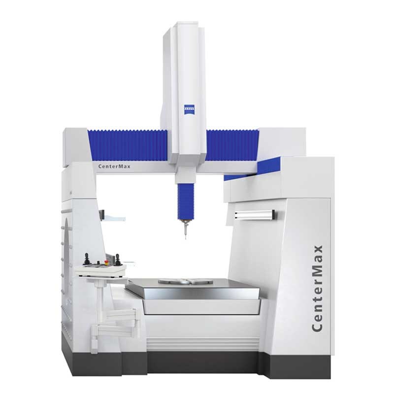
The base plate and linear axes are made of temperature-stable materials. This ensures excellent temperature behaviour of the entire measuring system. To guarantee the highest precision, air bearings are used in all axes. The optimum measuring system can be configured depending on component size, component weight and measuring requirements. Different pick-up heads and probe systems allow an optimal adjustment to your measuring tasks.
The LH series with rotary table measures rotationally symmetrical precision components as well as prismatic components quickly and reliably. The numerous models and equipment options allow for optimal matching to your measuring requirements.

All measuring machines of the LH series can also be configured with an integrated rotary table. This enables both the precise 4-axis measurement of rotationally symmetrical components and the reliable measurement of the entire spectrum of prismatic components.

All three axis movements are controlled from the one joystick. Moving the joystick left, right, backwards and forwards controls the CMM X and Y movements. The Z-axis is controlled by twisting the joystick clockwise and anti-clockwise (configurable)*.
If a trigger event occurs during joystick operation, the CMM will stop and back away from the surface along the vector that it was travelling. After the back off operation, it is necessary for the joystick to return to its null position for a set period of time before the joystick will permit movement of the CMM. The default value is 0.05 seconds*. The back-off speeds and distances are defined by the UCC configuration settings*.
The joystick enable button(s) are intended to be used to prevent the accidental movement of the machine. Two actions are required to initiate CMM motion: press joystick enable button and operate the joystick.
These permit the locking of one or more axes of the CMM, ignoring any joystick deflections for that axis. On each of the axis lock buttons there is an LED indicator that will light red when the respective axis is locked. On the MCU display there will also be a padlock symbol next to the respective axis (see below). These buttons toggle the lock on / off.
When the MCU is in head mode, the axis locks are applied to the relevant head axes. When the joystick is in head mode and a REVO / REVO-2 / PH20 head is fitted, the left / right axis lock button is used to initialise and cancel ‘SNAP ON". ‘SNAP ON" is the ability to move the head to the nearest multiple of a defined head angle. In UCCassist-2 the variable can be set to define the resolution of manual head moves (e.g. 5°). These axis locks will only be active during manual (MCU) controlled CMM movements. When the CMM is under DCC (direct computer control) operation, all axis locks will be released and re-latched when returning to manual operation.
This button is designed to allow the user to record or cancel chosen machine positions. When a program is being generated by the teach and learn method, the take point button is used to permit the CMM to record a waypoint and use it in the program. Use of the cancel point button will indicate to the application software that the point just taken (either a touch point or a position generated by the take point button) should be removed from the program. The cancelling process can be repeated many times and the front-end program will use it to delete multiple stored points.
In this axis system, the joystick directly controls the machine axes, i.e. a forward deflection of the joystick produces a pure Y+ movement of the CMM. This is the default machine setting when the machine is initialised.
The axis system in which the MCU is moving the CMM (machine, part co-ordinate or stylus) is indicated on the LCD by an M, P or S and by a tri-colour LED mounted below the axis select button. Pressing the axis select button will enable the user to scroll through the three axis systems.
The joystick orientation button changes the mapping of joystick deflection direction to CMM axis. This allows the user to move freely around any side of the CMM and transpose the joystick orientation such that the machine"s X-axis and Y-axis correspond to joystick direction of deflection. If any axis lock is asserted and the joystick orientation is changed then the relative axis lock will also be transposed.
NOTE:When switching the system to CMM auto mode, the joystick orientation feature will drop out and then be reasserted when the system is placed into CMM manual mode.
This button switches between CMM and rotary table operation.If there is no rotary table this button has no effect. The rotary table is set up during commissioning in UCCassist-2.
The engage button gives the CMM user the ability to engage or disengage the servos whilst the CMM is in manual mode. This button is configured as a toggle switch and has an associated LED to indicate the servo status. The LED identifies the various operational states as listed below. A symbol at the top of the LCD screen (shown below) also indicates whether the servos are engaged.
The STOP button gives the operator the ability to rapidly stop the CMM, REVO head and PH20 without disengaging. When the CMM has stopped, the system stays in hold state with both the CMM and head engaged.
This is the yellow or grey STOP button mounted on the MCU W-2 joystick, or the grey button on the MCU5-2. When this button is pressed, all CMM and motorised head motion is halted.
A red or grey emergency STOP switch is mounted on the MCUlite-2, MCU5-2 and on the MCU W-2 cradle which is hard wired to the UCC controller. It complies with EN13850 and when connected to a UCC / SPA the system can comply as either a category 2 or category B E-STOP system as defined in EN954-1:1996 (ISO13849-1:1999). When this switch is operated power to all the CMM axes is removed.
Speed override controls the machine speed when the CMM is running a program under DCC mode. It will also control the speed of the REVO head or PH20 if fitted. The LCD screen displays a percentage value of the programmed move speed when in DCC operation as shown below. If the speed override is set to less than 10%, the speed percentage shown on the LCD display will flash.
If the joystick is taken out of range while the CMM is moving in automatic mode the loss of the radio link will not stop the CMM, but if the speed control is changed while the joystick is out of range the following actions are required when the joystick is reconnected.If the new demanded speed is lower than the value set before the link was lost then the CMM will immediately slow down to the new speed when the joystick link is reconnected.
If the new demanded speed is higher than the value set before the link was lost then, when the joystick link is reconnected, the CMM will keep on moving at the old speed but the display of % speed will be reversed (white on black as shown below). The speed will be frozen until the speed control is turned down through the old speed value. The speed control will then again be functional.
The probe disable button gives the CMM user the ability to move the CMM while the probe is triggered or disconnected by disabling the probe trigger signal.
WARNING:When operating in this mode the probe is disabled and therefore probe contact with a surface will NOT stop the CMM. No measured data will be returned to the CMM host computer.
The probe disable function will only work while in manual mode and cannot be applied while in automatic / DCC mode. To disable the probe, press and hold the joystick enable button and then press the probe disable button. The CMM can now be moved irrespective of the probe trigger status. Releasing the joystick enable button cancels the probe disable function. In all modes the application of probe disable is confirmed by the red probe disabled LED being illuminated.

The XR20 rotary axis calibrator works in conjunction with XL-80 and XM-60 laser systems providing highly accurate, repeatable rotary axis calibration for stages, jigs and machine tools.
A mounting ring adaptor plate enables the XR20 rotary axis calibrator to be fitted to rotary tables with unsuitable centre recesses. It can also be used to secure the XR20 rotary axis calibrator to the chuck (lathe) adaptor and custom mounts.
CARTO software suite is used for capturing data, analysis and rotary measurement using the XL-80 laser or XM-60 multi-axis calibrator. CARTO is made up of three applications:Capture to collect laser measurement data.
Off-axis rotary measurement mode in the CARTO software suite provides a single source for testing off-axis measurement using the XR20 rotary axis calibrator and XL-80 laser system. This streamlines the measurement of rotary positioning accuracy for 5-axis machine tools, where the XR20 rotary axis calibrator cannot always be mounted on the centre of rotation.
Off-axis rotary measurement application in the CARTO software suite allows the XR20 rotary axis calibrator to be used to measure the rotary positioning accuracy of an axis, even when the XR20 isn"t mounted on the centre of rotation (pivot point) of that axis. This extends the capability of XR20 to many five axis machine tools.
The mounting of the XR20 rotary axis calibrator relative to the axis under test is vital for accurate measurement. Renishaw has developed the XR20 90° bracket to remove complexity of manufacture for the user. This accessory is manufactured to extremely fine tolerances required to achieve accuracy of testing.
Flexible fixturing options are provided by removable magnetic feet and a variety of through holes for direct bolt attachment. The bracket is useful for meeting the mounting requirements of "off-axis" rotary measurements and resolving "on-axis" mounting difficulties on trunion type machines.
The Renishaw XR20 rotary axis calibrator uses Bluetooth® wireless technology. In some territories the level of regulation varies. This table indicates the relevant standards or licensing authority that XR20 complies with, for indicated territories and the corresponding registration number, where applicable.[183kB]

Wenzel Metrology equipment is used in a wide range of manufacturing industries including aerospace, automotive and medical. The Wenzel range includes, bridge and horizontal arm CMM"s driven by Wenzel Metromec and OpenDMIS CMM software and equipped Renishaw probes.
Wenzel has also introduced a new industrial CT Scanning workstation, laser scanning heads for non contact measurement and reverse engineering, and a new white light scanning solution for high speed scanning of Turbine Blades and Blisks as well as a new portable CNC 3D scanning system. Wenzel also offers its own 3D surfacing software for scanning and reverse engineering, Wenzel Pointmaster. If gear checking is required, Wenzel manufactures its own range of gear testing machines.
Located in Faridabad (Near NHPC Chowk Metro Station), Wenzel South Asia (p) Ltd. is also able to offer service, calibration & subcontract measurement . Also available are retrofits and upgrades to group or non group CMM?s. For larger applications there are a range of Wenzel CMM gantry machines and for styling studio"s Wenzel has a tailor made product solution.
LK Metrology presents an updated and extended range of high precision CMM rotary tables with our Surface and Flush mounted options! Click on the link below for more information!https://lkmetrology.com/lk_newsite/products/accessories/accessories-for-cmm/…


 8613371530291