
nikken rotary table maintenance manual made in china

New Nikken facility was opened at Zhao Hua Road, Shanghai on 2004 JAN due to the Chinese business expansion. The standard items of NC tooling & CNC rotary table and each important spare parts are stocked for quick delivery. You can access to Nikken China with Chinese, Japanese or English. Not only Chinese catalogue but also Chinese instruction manual are provided for Chinese domestic market. Our office has the show room to see and touch our products, and our presentation will be done more practically. Technical seminar of Nikken is also opened at user factory side. Chinese engineer well trained in Japan is engaged in the service of our products. Different types of the NC controller for the CNC rotary table are provided for the trial running after repair. The most important spare parts are stocked. It is possible to stock the special spare parts of the custom-made tooling or CNC rotary table for further discussion. Please consider to make a contract of “ Nikken Rotary Table Overseas Warantee Contract ” for the CNC rotary table delivered to China. The sales of nikken products through Internet is not started in China. For after service and the further maintenance, please purchase Nikken products through authorized distributors. NIKKEN CHINA 278

NIKKEN WORLD WIDE SALES BRANCH LOCATIONS KOREA NIKKEN (KOREA) ★ : Sales office with Service Engineer PROCOMO-NIKKEN (FRANCE) : Sales office : Service office NIKKEN SCANDINAVIA (SWEDEN) HEAD OFFICE & FACTORY There are overseas Sales Branch office in 14 countries. Each sales branch office has stocks for toolings and CNC Rotary Tables, and service engineers look after the maintenance and service operation of our products. In the other region, e.g. East-South Asia, Oceania, South America, Africa, etc., there are some distributors. At the production line abroad, as there are many requirements for special tools and CNC Rotary Table to suit the special specifications, please ask us or distributors for spare tools and maintenance parts in advance. NIKKEN CHINA (CHINA) NIKKEN DEUTSCHLAND (F.R.GERMANY) NIKKEN KOSAKUSHO WORKS, LTD. OSAKA, JAPAN. 5-1, 1-chome, Minamishinden, Daito-shi, Osaka-fu, Japan. Telephone:072-869-5820 Telefax:072-869-6220 U.S.A GERMANY ITALY SWITZERLAND SCANDINAVIA SWEDEN SPAIN & PORTUGAL LYNDEX-NIKKEN 1468 Armour Boulevard, Mundelein, ILLINOIS 60060 Tel.+1-847-367-4800 Fax.+1-847-367-4815 HERRAMIENTAS LYNDEX-NIKKEN S.A.de C.V. Av. Hercules #401-13, Fracc. Poligono 3 Santa Rosa Jauregui, Queretaro 76220 Tel.+52-55-8421-8421 PROCOMO-NIKKEN S.A.S 6, avenue du 1er Mai-Z.A.E.Les Glaises 91127 Palaiseau Cedex Tel.+33-(0)-1-69.19.17.35 Fax.+33-(0)-1-69.30.64.68 NIKKEN KOSAKUSHO EUROPE LTD. Precision House, Barbot Hall Industrial Estate, Rotherham, South Yorkshire, S61 4RL Tel.+44-(0)-1709-366306 Fax.+44-(0)-1709-376683 NIKKEN DEUTSCHLAND GmbH Eisenstraße 9c, 65428 Rüsselsheim Tel.+49-(0)-6142-550600 Fax.+49-(0)-6142-5506060 VEGA INTERNATIONAL TOOLS S.P.A Via Asti N 9 10026-Santena(TORINO) ・ Tel.+39-011-9497911 Fax.+39-011-9456380 NIKKEN SWITZERLAND AG Sumpfstrasse 32-CH-6300-Zug Tel.+41-(0)-41-748-5000 Fax.+41-(0)-41-748-5001 NIKKEN SCANDINAVIA AB Bultgatan 13b, 44240 Kungalv Tel.+46-(0)-303-440-600 Fax.+46-(0)-303-58177 CUTTING TOOL S.L(TOOLING) PORTUETXE 16, BARRIO IGARRA E-20018 DONOSTIA-SAN SEBASTIAN Tel.+34-(0)-902-820090 Fax.+34-(0)-902-820099 UTILLAJES OLASA,S.L.(CNC ROTARY TABLE) Tel.+34-(0)-669-603433 NIKKEN KESICI TAKIMLAR SAN. VE ULUSLARARASI TIC. A. S E5 Uzeri Kucukyali Yanyol Irmak Sok. Kucukyali Sanayi Sitesi A Blok No:5 Maltepe 34852 Istanbul Tel.+90-(0)-216-518-1010 Fax.+90-(0)-216-366-1414 KOREA NIKKEN LTD. 90B-11L, Namdong Industrial Complex, 170, Namdong-Daero, Namdong-Gu, Incheon, Korea 405-819 Tel.+82-(0)-32-763-4461 Fax.+82-(0)-32-763-4464 SHANGHAI ZHONG YAN TRADING CO., LTD. BUILDING 1/F, #54, No.1089 QINZHOU RD. (N) , SHANGHAI, CHINA Tel.+86-(0)-216210-2506 Fax.+86-(0)-216210-2083 NIKKEN KOSAKUSHO ASIA PTE, LTD. 186, WOODLANDS INDUSTRIAL PARK E5 #04-01 M SINGAPORE 757515 Tel.+65-6362-7980 Fax.+65-6362-7980 SIAM NIKKEN Co., LTD. 127 Moo5 Gauwungsai-Bangturie Road Tambon Tanokkard Ampher Muangnakhonpathom Nakhonpathom 73000 Thailand Tel.+66(02)178-0503 Fax.+66(02)178-0504 http://www.nikken-kosakusho.co.jp/en e-mail : export@nikken-kosakusho.co.jp/en Please contact to the following agent. NIKKEN KOSAKUSHO WORKS, LTD. D.LK.0.5 Specifi

CNC(Z)180 *Hardness of G95, G110 and G130 was 2008.2 6 10000~ CNC(Z)202 changed from 70 to 90. Internal tapered diameter of main gear (Worm shaft gear) CNC180R,L 11021~ Basic specification is ; φ11 - iF2 equivalent. φ16 - iF4 equivalent. CNCZ180R,L 10813~ But the Serial No. larger than left figures are standardized as follows; 2008.7.17 7 No“T”at the end of Code No. for φ11 e.g. 11021 CNC202R,L 10516~ Add“T”at the end of Code No. for φ16 e.g. 11021T And add“H”at the end of Code No. for rotary tables using the Harting connector CNCZ202R,L 10622~ on 21 controller. e.g. 11021HT CNC180R.L 15934~ *Decrease M4 tap of the thrust flange. CNCZ180R.L 12261~ (From 6 to 2) 2013.8 8 CNC202R.L 19864~ CNCZ202R.L 12084~ History of version revisions Details of what was revised in the versionDate Version Model Serial No. CNC180R.L 20000~ *O-ring was changed to Rod Seal CNCZ180R.L 20000~ (Piston Seal)2014.5 9 G-95→NIK-IW0340-950S CNC202R.L 25000~ G-110→NIK-IW0340-1100S CNCZ202R.L 20000~ G-130→NIK-IW0340-1350KCNC ROTARY TABLE CNC ROTARY TABLE
Table of Contents Page1. Preface 22. Dimensional drawings and specifications 23. Preparation for operation 3 3-1 Removal from packing 3 3-2 Installation onto the M/C 3 3-3 Filling lubrication oil 4 3-4 Electrical connection 5 3-5 Supplying the pneumatic pressure for the brake 6 3-6 Trial Running 7 3-7 Setting grid shift amount for machine zero-return 8 (only for additional axis control)4. Mechanism and Maintenance information 9 4-1 Mechanism location for main parts 9 4-1-1 Location of the solenoid valve, clamp / unclamp confirmation switches 10 4-1-2 How to change the solenoid valve specifications(ON-Clamp / OFF-Clamp) 11 4-2 Backlash adjustment 12 4-3 Brake mechanism and confirmation mechanism 17 4-4 Zero point return mechanism 185. Appendix 5-1 Relation between work diameter and length for allowable maximum load(for steel) 19 5-2 Relation between work diameter and length for allowable work inertia 19 5-3 Spare Parts List 20
1. Preface Thank you for your purchase of the Nikken CNC Rotary Table. The Nikken CNC Rotary Table is designed and manufactured on basis of our spirit of “Everyday research”, which words are the origin of our company name. We are sure that this CNC Rotary Table will satisfy you for its high performance, high quality and easy operation. Nikken CNC Rotary Table withstands long-term and full operation. In order to ensure its proper handling and full utility for intended purpose, please read through the instruction manuals attached hereto. And please keep it where the operator can refer to it whenever necessary.
If there should happen to be any trouble on the CNC Rotary Table, please inform us the details of trouble as well as all letters engraved on its nameplate.
3-1. Removal from packing 1)Unpacking and transfer Careful attention should be paid to the transfer of the CNC Rotary Table after it is WARNING unpacked. Hook a wire through the eye bolt and carefully move the CNC Rotary Table while keeping the balance. After the transfer please detach the eye bolt.
2)Wiping off rust-preventive oil Carefully wipe off the rust-preventive oil applied on the whole surface of the CNC Rotary Table when shipped by using waste cloth. Do not use benzene or gasoline which would produce rust.
3-3. Filling lubrication oil The entirely enclosed CNC Rotary Table body will not permit the ingress of cutting oil or permit lubrication oil to leak out. However, be sure to check the oil level, and inspect the sight glass about once a week. If the oil level is low, replenish it with the appropriate amount. Oil should be changed at least once a year. Since the appropriate amount of Idemitsu’s Super Multi Oil #100 was filled before the rotary table was shipped, there is no need to add any more lubrication oil.
List of recommended oil: Please see Common Instruction Manual. 4 CNC ROTARY TABLE
3-4. Electrical connection Always make sure that the electrical connection between the CNC Rotary Table and the machine controller is done according to the attached electrical circuit diagram. Rotating the CNC Rotary Table with the brake clamped would damage the CNC Rotary Table. Note 1) The cable connection and checking must be done when the main power of the machine tool is switched off.DANGER Note 2) Ensure that the cables and the pneumatic hose are located safely without causing any interference against the movement of the machine table.
3-5. Supplying pneumatic pressure for the brake [1]Supplying the air The brake clamp on this table is activated by pneumatic pressure. The solenoid valve and confirmation switches for clamp / unclamp are provided inside the motor cover. Please connect air supply hose to the specified port. 1)The standard position where the air is connected is located next to the cable output port. The port has Rc1/4 fitting for 8mm diameter air hose.(Please refer the attached drawings for details.) 2)Always make sure that the brake clamp requires 0.49MPa constant pneumatic supply pressure. 3)The applicable pneumatic pressure range is between 0.40MPa - 0.70MPa. However, if the pressure is below 0.49MPa, the sufficient brake torque in the specifications cannot be obtained, and if the pressure is over 0.70MPa, it might damage the solenoid valve, switches for clamp / unclamp confirmation, and the air hose, so care must be exercised. 4)Supply clean and dry air for the pneumatic pressure for the clamp. Manifold(There are 2 types) (Solenoid Energized: Clamp) (Solenoid Energized: Unclamp)
CNC180 Clamp / Unclamp Conf. SW. FL7M-2J6HD Solenoid Valve Air Purge VQZ2151-1(5・ )YZ-M5-X77 6mm Dia. Straight Connector with Air Leakage Hole Change the connectors, if air purge is not suitable for your application.
3-6. Trial Running 1)Make sure that the air hose is connected and the pneumatic pressure is supplied correctly. 2)Do not load any component on the CNC Rotary Table. 3)Execute the brake clamp(M10, M68 etc)and unclamp(M11, M69 etc)commands repeatedly from NC unit to check the brake works properly.
When the CNC Rotary Table is controlled by the Nikken Alpha 21, use G10 (Unclamp command) and G11 (Clamp command) signal instead. N000 G10 G13 (Unclamp, Single Block Mode) N001 J000 G11 (Clamp and then Jump to N000)
4)Rotate the CNC Rotary table clockwise and counter-clockwise about twice at low speed (F300) for the first time, and make sure that the CNC Rotary Table rotates smoothly, then gradually increase the speed up to the rapid speed.
3-7. Setting grid shift amount for machine zero-return (only for additional axis control) The machine zero point of the CNC Rotary Table is located at the position where the CNC Rotary Table reference T-slot becomes parallel with the CNC Rotary Table bottom surface and the base line plate indicates“0”position.
The grid shift amount is described at the individual parameter list. And regard this amount as the compensation amount. 1)Input the compensation amount at the NC parameter of grid shift amount. 2)Rotate the CNC Rotary Table a few degrees to the clockwise direction by JOG mode, then carry out the machine zero return. 3)Adjust the compensation amount with checking the CNC Rotary Table zero position by dial gauge reading. Repeat 1)~ 3)operation to obtain the correct grid shift amount.
Caution1: The motor flange and / or motor cover before ser. No. 5000 cannot be installed on the rotary table with motor cover sealed with O-ring. Caution2 : Depending on the type of motor(eg. MELDAS HC-52T), power connector may interfere with the valve unit. If this is the case, use separate type(a combination of the VZ3120 and ZC130A-BTS6). Caution3: The solenoid valve is replaced for each solenoid valve unit VQZ2151-1(5)YZ-Q-X77 (with base unit). The VQZ2151-5YZ-Q-X77 type is for the DC 24V, and the VQZ2151-1YZ-Q-X77 type is for the AC 100V.
4-1-2 How to change the solenoid valve specifications(ON - Clamp / OFF - Clamp) There are 2 types of manifold of“R”and“L”as follow. Right hand rotary table:“R”manifold is installed as the standard(OFF - Clamp). Left hand rotary table:“L”manifold is installed as the standard(OFF - Clamp). If you switch the solenoid valve specification from“OFF – Clamp”to“ON – Clamp”, the manifolds are changed from“R to L”for right hand rotary table, and from“L to R”for left hand rotary table. Also, swap clamp conf. SW & unclamp conf. SW (Refer to the photo below.)
(Example of replacement on a right hand rotary table)From“OFF – Clamp”to“ON – Clamp”Clamp conf. SW Unclamp conf. SW Unclamp conf. SW Clamp conf. SW(Red tube) (Blue tube) (Blue tube) (Red tube)“R” manifold “L” manifold R
(Example of replacement on a left hand rotary table)From“OFF – Clamp”to“ON – Clamp”Clamp conf. SW Unclamp conf. SW Clamp conf. SW Unclamp conf. SW(Red tube) (Blue tube) (Red tube) (Blue tube)“L” manifold “R” manifold L
Caution:The air is full inside the motor cover to prevent the coolant ingress (Air purge) from the rotary table with the motor cover sealed by O-ring. Small volume of air leaks from straight connector and comes out from bottom of motor cover. You may recognize air leaking sound. This is normal. Do not block the air venting hole used for air purging. Doing it may cause malfunctioning.
4-2. Backlash adjustment [Check of the backlash] The worm screw rotates in the totally-enclosed oil bath and the reduction mechanism is composed of a combination of the special ion-nitrided worm wheel and the special worm screw, so that it is not necessary to adjust the backlash until 4~5 years have elapsed after the rotary table is put in service. However, if it’s necessary, the backlash can be simply adjusted according to the following procedures.
1)Unclamp the brake 2)Confirming the backlash Put the dial gauge(a)probe at the T-slot on the faceplate. Read a deflection of the dial gauge(a)by inserting the flat steel plate(H)into a T-slot and maneuver the faceplate clockwise and counter clockwise through the plate by hand at 9.8~14.7N・m force. A backlash of within 5~15 microns(at least 5 microns of backlash is necessary)is normal, and the adjustment should be done in the event when a backlash of 50 microns or more is observed. The confirmation is to be done on 8 spots of every 45°of table.
3)Backlash adjustment at worm wheel 1)Remove the eccentric housing cover. 2)Slightly loosen 3 bolts(c) (M8)which tighten the eccentric housing. 3)Remove the cap plug(d)off. 4)There is a bolt(e)for clamping the eccentric housing behind the plug, loosen the bolt 2~3 turns and hit the bolt head slightly to release the clamp piece(f)behind. Thus, the clamping of the eccentric housing will be released and now it’s ready to adjust the backlash.(See Fig. 12.) 5)Here, reset the dial gauge probe(a)as shown in Fig. 9, and loosen the backlash adjust bolt(h)and tighten the backlash adjust bolt(i), then the eccentric housing will turn and the backlash between the worm screw and worm wheel will get near to 0 (zero).(See Fig.11) Adjust the backlash to 5~15 microns by watching the deflection of the dial gauge (a)while maneuvering the outer periphery of CNC Rotary Table. (See Fig. 9) 6)After completion of above adjustment, put(c) ( , e)and(d)back as they were. 7)Measure the backlash again and confirm to that it has been adjusted to 5~15 microns.
4-3. Brake and confirmation mechanism 1)When the air pressure is supplied inside the cylinder by the clamp command, the piston travels along its stroke. Through a 2-stage intensifying mechanism, the wedge piston with its gentle taper presses the entire circumference of the brake disk linked to the table against the main body, resulting in the clamping status. When this happens, the air pressure is also supplied to the brake confirmation mechanism, the piston is driven, and the proximity switch for clamp confirmation is actuated. 2)When the pneumatic pressure for clamping is released by unclamp command, the piston is pushed back to the original position by the return spring to make it unclamp. At the same time, the pneumatic pressure at the brake confirmation mechanism also pushes the piston to the original position and activates the proximity switch for unclamp confirmation is actuated.
Note 1)When changing the proximity switch, locate the switch to get the length of 18 mm from flange to the front end as Fig. 15. (If the adjustment is not made, it might cause the interference against the dog ring or the machine zero positioning might not be done properly.) Note 2)For the installation on the special purpose machine(for special application), the proximity switch for the machine zero point return might not be installed due to the machine specifications. Please refer to the attached drawings with CNC Rotary Table.
Reference No. Part No. Item Qty. Remarks TCZ-A3001 1a Face Seal 1 Dia.164mm with O Ring (MITSUBISHI) TCZ-A3001 2 CN180R002 Circular Table 1 TCZ-A3001 3 WW-CN180R003 Worm Wheel 1 TCZ-A3001 4 CN180R004 MZR Dog Ring 1 TCZ-A3001 6 CN180R006 Radial Retainer 1 TCZ-A3001 6a Needle Roller 36 DIA.4mm x 11mmL TCZ-A3001 7 CN180R007 Thrust Retainer 1 TCZ-A3001 8 CN171R035 Tubular Roller 36 TCZ-A3001 11 AX123R041 Spacer Ring 1 TCZ-A3001 12 AX123R042 Brake Disk 1 TCZ-A3001 13 AX123R043 Brake Disk Set Ring 1 TCZ-A3001 14 CN105R034 Coil Spring 7 TCZ-A3001 15 AX123R046 Clamp Ring 1 TCZ-A3001 16 AX123R047 Retainer 1 TCZ-A3001 16a Ball 24 φ10 TCZ-A3001 17 CN180R017 Pilot Flange 1 TCZ-A3001 17b Rod Seal *3 1 NIK-IW0340-1100S TCZ-A3001 17c O Ring 2 G-145 TCZ-A3001 18 CN180R018 Piston 1 TCZ-A3001 18a Rod Seal *3 1 NIK-IW0340-950S TCZ-A3001 18b Piston Seal *3 1 NIK-IW0340-1350K TCZ-A3001 19 CN180R019 Cylinder Cover 1 TCZ-A3001 19a Combination Bearing 1 NAX6040 (IKO) TCZ-A3001 19b Oil Seal 1 UE7510010 (MUSASHI) TCZ-A3001 19c O Ring 1 G-130 TCZ-A3002/1 21 WS-CN180R055 Worm Screw *4 1 TCZ-A3002/1 21a Ball Bearing 2 #6003 (P5) (NTN) TCZ-A3002/1 21b Snap Ring 1 ISTW-17 (OCHIAI) TCZ-A3002/1 21c Key 1 WA4 x 13 TCZ-A3002/1 22R CN180R022 Eccentric Housing *1 1 FOR RIGHT HAND TABLE TCZ-A3002/1 22L CN180L022 Eccentric Housing *1 1 FOR LEFT HAND TABLE TCZ-A3002/1 22c Oil Seal 1 SC17358 (NOK) TCZ-A3002/1 22d Oil Seal *1 1 TC25387 (NOK) TCZ-A3002/1 22e O Ring 1 G-50 TCZ-A3002/1 22f Thrust Needle Bearing *1 2 AXK1103 (NTN) TCZ-A3002/1 22g Inner Ring *1 2 WS81103 (NTN) TCZ-A3002/1 22h Outer Ring *1 2 GS81103 (NTN) TCZ-A3002/1 22i Needle Bearing *1 1 NK1720R (NTN) TCZ-A3002/1 23 AX123R059 Seal Collar 1 TCZ-A3002/1 23a O Ring 1 WP-13 TCZ-A3002/1 24 CN171R022 Nut A for Worm Screw 1 TCZ-A3002/1 25 CN171R023 Nut B for Worm Screw 1 TCZ-A3002/1 26 CN180R026 Bearing Collar 1 TCZ-A3002/1 28 GR-CN202R015 Main Gear *4 1 TCZ-A3002/1 29 GR-CN180B028-16T-K5 Motor Gear *4 1 TCZ-A3002/1 31R AX123R064R Eccentric Cover *1 1 FOR RIGHT HAND TABLE TCZ-A3002/1 31L AX123R064L Eccentric Cover *1 1 FOR LEFT HAND TABLE TCZ-A3002/1 32 CN180R032 Clamp- Piece 1 TCZ-A3001 37 AX123R068 Straight Pin 1 TCZ-A3002/1 38 CN180R038 Seal Collar 1 TCZ-A3002/1 B28 GR-CN180B028 Main Gear *1 1 B Type TCZ-A3002/1 B29 GR-CN171B110 Motor Gear *1 1 B Type TCZ-A3002/1 B102 CN180B102 Idle Gear Flange *1 1 B Type TCZ-A3002/1 B102a O Ring *1 1 B Type P-16 TCZ-A3002/1 B102b Snap Ring *1 1 (OCHIAI) B Type ISTW-15 TCZ-A3002/1 B102d Ball Bearing *1 2 (NTN) B Type #6902 TCZ-A3002/1 B103 GR-CN180B103 Idle Gear *1 1 B Type TCZ-A3002/1 B103a Snap Ring *1 1 (OCHIAI) B Type IRTW-28 TCZ-A3002/1 B45 9ZL16-NUT Nut *1 1 B Type *1:updated 2006/OCT/04 *2:updated 2010/JUL/22 *3:updated 2014/AUG/18 22 *4:updated 2015/JUL/16 CNC ROTARY TABLE
23NIKKEN KOSAKUSHO WORKS, LTD. OSAKA, JAPAN.5-1, 1-chome, Minamishinden, Daito-shi, Osaka-fu, Japan. Telephone:072-869-5820 Telefax:072-869-6220U.S.A LYNDEX-NIKKEN KOREA KOREA NIKKEN LTD.CA, CT, IL, NC, TX, WA 1468 Armour Boulevard, 90B-11L, Namdong Industrial Complex, 170, Namdong-Daero, Mundelein, ILLINOIS 60060 Namdong-Gu, Incheon, Korea 405-819 Tel.+1-847-367-4800 Fax.+1-847-367-4815 Tel.+82-(0)-32-763-4461 Fax.+82-(0)-32-763-4464MEXICO HERRAMIENTAS LYNDEX-NIKKEN S.A.de C.V. P.R.CHINA SHANGHAI ZHONG YAN TRADING CO., LTD.(From 2014.09) Av. Hercules #401-13, Fracc. Poligono 3 Building 1/f, #54, No.1089 Qinzhou Rd.(N), Santa Rosa Jauregui, Queretaro 76220 Shanghai, China Tel.+52-55-8421-8421 Tel.+86-(0)-216210-2506 Fax.+86-(0)-216210-2083FRANCE PROCOMO-NIKKEN S.A.S SINGAPORE NIKKEN KOSAKUSHO ASIA PTE, LTD. 6, avenue du 1er Mai-Z.A.E.Les Glaises 91127 186,Woodlands Industrial Park E5 #04-01 Palaiseau Cedex M Singapore 757515 Tel.+33-(0)-1-69.19.17.35 Fax.+33-(0)-1-69.30.64.68 Tel.+65-6362-7980 Fax.+65-6362-7980UK NIKKEN KOSAKUSHO EUROPE LTD. Precision House, Barbot Hall Industrial Estate, THAILAND SIAM NIKKEN Co., LTD. Rotherham, South Yorkshire, S61 4RL 127 Moo5 Gauwungsai-Bangturie Road Tambon Tanokkard Tel.+44-(0)-1709-366306 Fax.+44-(0)-1709-376683 Ampher Muangnakhonpathom Nakhonpathom 73000 Thailand Tel.+66(02)178-0503 Fax.+66(02)178-0504GERMANY NIKKEN DEUTSCHLAND GmbH Eisenstraße 9c, 65428 Rüsselsheim Tel.+49-(0)-6142-550600 Fax.+49-(0)-6142-5506060ITALY VEGA INTERNATIONAL TOOLS S.P.A Via Asti N・9 10026-Santena(TORINO) http://www.nikken-kosakusho.co.jp/en Tel.+39-011-9497911 Fax.+39-011-9456380 e-mail : export@nikken-kosakusho.co.jpSCANDINAVIA NIKKEN SCANDINAVIA ABSWEDEN Malmövägen 14 331 42 Värnamo Sweden ■Please give your order to the following agent. Tel.+46-(0)-303-440-600 Fax.+46-(0)-303-58177SPAIN & CUTTING TOOL S.LPORTUGAL Portuetxe 16, Barrio Igarra E-20018 Donostia-san Sebastian Tel.+34-(0)-902-820090 Fax.+34-(0)-902-820099 UTILLAJES OLASA,S.L. Tel.+34-(0)-943-107177TURKEY NIKKEN KESICI TAKIMLAR SAN. VE ULUSLARARASI TIC. A. S E5 Uzeri Kucukyali Yanyol Irmak Sok. Kucukyali Sanayi Sitesi A Blok No:5 Maltepe 34852 Istanbul Tel.+90-(0)-216-518-1010 Fax.+90-(0)-216-366-1414 D.ML .0.3 ●Specifications are subject to change without notice.
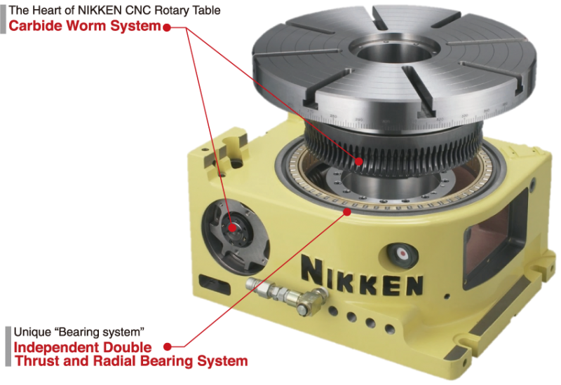
2 CNC ROTARY TABLE CNC ROTARY TABLE for Full Automation Ion Nitrided Worm Wheel HV980 Steel Way HRC58 Carbide Worm Screw Photo shows the worm system of CNC401. Work Sample Please see for more work samples. P.37 and P.46 Multi-setting on multi-planes P. 44 1
3 Carbide Worm Screw CARBIDE WORM SYSTEM Anti-Wearing, High Rigidity and High Speed Rotation Carbide Worm Screw, hard and strong against high speed rotation, is used. (Photo at right hand side)[material : V grade Carbide: High anti-wearing and tough quality] Ultra heavy duty, maintaining the high accuracy semi-permanently. Comparing with the traditional combination of worm system (phosphor bronze, aluminium bronze worm wheel and steel worm screw), wearing is largely reduced and table is usable for much more years, resulting in great cost-down. For better impact capability, the special alloy steel worm screw is used for the worm system of the small tooth module. Worm Wheel Material is special NIKKEN order made steel. Specially hardened and furthermore ion-nitrided on the tooth. Thus, the problem of the sliding friction is solved. The hardness of the tooth surface and inside is shown at right hand side. Depth 0.1mm HV980 Fig. 2 Inside HRC36 Hardness of Worm Wheel (micron) Backlash(Amount of wearing) Backlash Compensation 3mon. 6mon. 12mon. 2yrs. 3yrs. Useful Life Fig.1 Phosphor Bronze /Aluminium Bronze Worm Gear (22.2min -1 ) NIKKEN CNC Rotary Table CNCZ 2 (66.6min -1 ) Rotation speed of motor = 3,000min -1 Dynamic High Pressure Oil Film Effect for High Speed CNC Rotary Table Z Series NIKKEN"S experience in gear cutting and study of the pressure angle of worm screw carry out the table"s higher rotation speed (66.6min -1 ). The rotational speed of the screw creates the pressure to force the oil between the gears preventing any metal-to-metal contact, eliminating gear wear and producing high rigidity and durability. Large size rotary tables are made a lineup The large size rotary tables for the large size machine tool, the large size die mould, energy and air craft are made a lineup. P.11, P.29 The NIKKEN carbide worm system is installed in the rotary table with the super durability, accuracy and rigidity. Dynamic High Pressure Oil Film CNC11 5AX-10 CNC10 CNC0 Turbine Blade High Speed CNC Rotary Table Z series for high speed milling marked arrow. 2
4 INDEX CNC105,0,2 COMPACT CNC ROTARY TABLE P. 56 COMPACT ROTARY TABLE with 21 CONTROLLER P. 69 CNC100-2W,3W,4W,CNC0-2W,CNC2-2W,CNC2-2W MULTI-SPINDLE CNC ROTARY TABLE P. 19 CNC2,302,321,401,501,1,803,1003,B350,B450,802 CNC ROTARY TABLE P. 710 CNC ROTARY TABLE with 21 CONTROLLER P CNC1000, 10, 11, 10, 00 LARGE CNC ROTARY TABLE P LARGE ROTARY TABLE with 21 CONTROLLER P. 70 CNC0B,2B,2B,302B,321B,401B BACK SIDE MOTOR MOUNTED CNC ROTARY TABLE P CNC0T, 2T, 302T, 321T, 401T, 501T, 1T TOP SIDE MOTOR MOUNTED CNC ROTARY TABLE P. 5AX-130, 1, 230,, 350, 550, 800, 10 TILTING ROTARY TABLE P TILTING ROTARY TABLE with 21 CONTROLLER P AX-2MT, 4MT MULTI-SPINDLE TILTING ROTARY TABLE P NST,300,500 MANUAL TILTING ROTARY TABLE P CNC503H 5AX-T400 NSVZ0, 300 NSVX400, 500 Indexing Accuracy (±2 ) ULTRA PRECISION ROTARY HIRTH COUPLING INDEX P NSVZ: Min. Command Incremental = 1 NSVX: Min. Command Incremental = 1, BUILT-IN TYPE CNC ROTGARY TABLE CNC401H, CNC503H P. 35 5AX-T400, -B450 P. 36 This is a CNC rotary table specially designed to be built into the machines. CNC Rotary Table for BROTHER T/C & P CNC Rotary Table for FANUC ROBO DRILLP. 42, P.44 3 DD, 400, 500, 5AX-DD0 Tilting Rotary Table with DD Motor for FANUC ROBO DRILL P. 4345
5 Optional Specification, Accessories & Technical Information Ample Accessories are available for NIKKEN CNC Rotary Table. For the additional or special specification, please fill in the specification mark sheet, and attach to your order. For the rotary tables marketing in EU, please order specifying "With CE Mark". All rotary tables are available with CE Mark. Optional Accessories AWC SYSTEM P.4748 Automatic Work Change system Series Attachment P.46 SCROLL CHUCK & POWER CHUCK P.49 TAILSTOCK P.50 Air/Air Booster & Air/Hydraulic Booster P.55 Air to Air and Air to Hydraulic Intensified Booster Hydraulic Unit P.46 Fitting Metals and Stepped Guide Pieces P.22 Special Specifications Servo Motor List P.37 Accuracy Standard P.52 Accuracy and measuring method Ultra Precision P.53 Rotary Joint P.54 Rotary connection for pneumatic/hydraulic fixture/chuck Built-in Pallet Clamp System P.55 Suitable for automatic pallet changer Water Proof Specification P.55 Available for waterproof connector and cable Special Application P.5758 World wide example and application Assessment of CNC ROTARY TABLE P.56 Technical Information of CNC ROTARY TABLE P.59 Load calculation, Indexing time, Durability and Instruction Indexing of the turbine shaft NIKKEN is keeping the manufacturing not only the quality, but also the safety in mind. Please be careful for the content maked. e.g. P. Nikken Controller 21 Controller P.6162 Technical Information for 21 Controller P.6368 Termination of the maintenance work for NIKKEN controllers CNC Rotary Table with 21 Controller P.6972 Selection of the CNC ROTARY TABLE P.73 NIKKEN EUROPE (UK) LYNDEX-NIKKEN (U.S.A.) Nikken Worldwide Network HEAD OFFICE & FACILITY P.7476 OVERSEAS SALES & SERVICE NETWORK P.77 NIKKEN CHINA (CHINA) P.78 LYNDEX-NIKKEN (USA) P.79 NIKKEN EUROPE (UK) P.80 NIKKEN DEUTSCHLAND (GERMANY) P.81 PROCOMO-NIKKEN (FRANCE) P.82 4
6 Item / Code No. Diameter of Table φmm Diameter of Spindle Hole φmm Centre Height mm Width of T Slot mm Clamping System Clamping Torque Nm GD Table Inertia at Motor Shaft 2 4 m Servo Motor min -1 MIN. Increment Rotation Speed min -1 Total Reduction Ratio Indexing Accuracy sec Net Weight Vertical Work Load on the Table COMPACT CNC ROTARY TABLE CNC105 Specifications Horizontal 21 and attachments CNC105 CNCZ φh7 φ φ10h7 Pin hole Air if1/ (44.4) 1/90(1/45) ±30 32 Wide application can be offered from small Drilling Press to M/C. Suitable for indexing/leads cutting of small size work pieces. Various kinds of the work chucking attachments can be offered from 5C collet fixtures to the air/hyd. chuck. P. 46 Explanation of the Code No. (Example) CNC 105 L F A - M ( ):High Speed CNC ROTARY Table Z series No Letter: without motor M: with Motor No Letter: DC servo motor A: AC servo motor Motor Maker P. 37 A21: with NIKKEN 21 controller F:FANUC M:MELDAS Y:YASNAC OSP:OSP T:TOSNUC N:NEC S:SANYO Z:SIEMENS I:INDRAMAT H:HEIDENHAIN X:ISOFLEX SEM:SEM B:BOSCH No letter: Right hand mounted motor L: Left hand mounted motor Diameter of Table 105, 0, 0 CNC: Standard CNCZ: High Speed Z series CNC0 CNCZ0 0 φh7 φ Air if2/ (44.4) 1/90(1/45) ± 45 CNC2L Rotary table with 21 controller, refer P.69 CNC2 CNCZ2 0 φh7 φ Air if4/ (44.4) 1/90(1/45) ± 55 5 Thrust Load applicable on the Table Guide Line of Unbalancing Load Work Inertia Driving Torque 1 2 Vertical 3 GD 2 4 N FL Nm FL Nm m m 2 Nm 1 This is the strength of the worm wheel without brake. It is applied against dynamic cutting thrust. 2 The guide line of MAX unbalancing load means the unbalancing load, when the rotary table is used with support table in vertical application. The guide line figure will be different according to the servo motor, please refer P.37 for more detail. 3 Driving torque means the torque at rotation speed after acceleration. Driving torque is almost constant and independent from the load except unbalancing load is applied. L type (Motor is mounted at left hand side) is available for all rotary tables. if4/5000 motor can be mounted on CNC0. AWC system is available for all rotary tables, please refer P.47P.48. Ultra precision type is available for all rotary tables, ±3 or ±5, please refer P.53. Rotary joint is available for all rotary tables, please refer P.54.
7 CNC105,0,2 CNC105, CNCZ105 External dimensions will be different according to the type of the servo motors. Dimensions with FANUC motor or with NIKKEN 21 controller ( 21 : ) are shown. Please contact with us for CAD data (2D:DXF, 3D:PARASOLID) ( 21:313) 252( 21:2) Powerful Brake Brake Torque : 5Nm φ φ 40 φ30 Photo shows a rotary table with 0 21 controller ( 21:128) Air purge function is provided inside the motor cover as standard. CNC0, CNCZ ( 21:326) 106 3( 21:2) Powerful Brake Brake Torque : 303Nm φ φ 55 φ40 Photo shows a rotary table with controller :130 Air purge function is provided inside the motor cover as standard. CNC2, CNCZ ( 21:346) ( 21:240) Powerful Brake Brake Torque : 303Nm φ φ φ ( 210) Photo shows a rotary table with 21 controller. Air purge function is provided inside the motor cover as standard. For accuracy standard, refer P.51, 52 For scroll chuck, tailstock and other optional accessories, refer P.49,50 For fitting metal and stepped guide piece, refer P.22 series attachment can be attached for all tables, refer P. 46 Counter Balance Cylinder Counter Balance Cylinder is standardized to solve un-balancing load. JAPAN. PAT Counter Balance Cylinder CNC0A Un-balancing Load Photo and illustration show the example of the application for un-balancing load. Small Size Support Table TAT(JAPAN. PAT) E A (105 2 ) 5 CST , 135 (w/o brake) TAT105 D C B Pneumatic ports are 2 x Rc1/8. Solenoid valve and clamp/unclamp confirmation switches are not included. Please add - centre height at the end of Code No. for the support table with different centre height (B). e.g.tat Code No. TAT105 TAT170 A 5 5 B C D E Clamping System Air Air Brake Torque 5 5 Weight Air pressure is 0.5MPa. (Nm) () Double intensifying clamping mechanism is installed on TAT105 & TAT170. Rotary joint is available for all models, refer P.54 6
8 CNC ROTARY TABLE Specifications Item / Code No. Diameter of Table φmm Diameter of Spindle Hole φmm Centre Height mm Width of T Slot mm Clamping System Clamping Torque Nm Table Inertia at Motor Shaft GD 2 4 m Servo Motor min -1 MIN. Increment Rotation Speed min -1 Total Reduction Ratio Indexing Accuracy sec Net Weight Work Load on the Table Vertical Horizontal CNC2 CNC2 CNCZ2 2 φ80h Air/ 588 / if4/ (33.3) 1/1(1/) CNC302 CNCZ φ80h Air/ 588 / if4/ (33.3) 1/1(1/) The rotary table can be used vertically or horizontally depending on the application. Explanation of the Code No. (Example) CNC 2 L F A - M ( ):High Speed CNC ROTARY Table Z series No Letter: without motor M: with motor No Letter: DC servo motor A: AC servo motor Motor Maker P. 37 A21: with NIKKEN 21 controller F:FANUC M:MELDAS Y:YASNAC OSP:OSP T:TOSNUC N:NEC S:SANYO Z:SIEMENS I:INDRAMAT H:HEIDENHAIN X:ISOFLEX SEM:SEM B:BOSCH No Letter: Right hand mounted motor L: Left hand mounted motor Diameter of Table 2, 300, 3, 400 CNC: Standard CNCZ: High Speed Z Series CNCB: Big Bore Rotary table with 21 controller, refer P.69, P.70 CNC321 CNCZ321 3 φ105h if12/ (44.4) 1/90(1/45) CNC401 CNCZ φ105h if12/ (44.4) 1/90(1/45) CNCB φ4h if12/ / Thrust Load applicable on the Table 1 N FL Nm Guide Line of Unbalancing Load Work Inertia Driving Torque 2 Vertical 3 GD 2 4 FL Nm m m 2 Nm This is the strength of the worm wheel without brake. It is applied against dynamic cutting thrust. 2 The guide line of MAX unbalancing load means the unbalancing load, when the rotary table is used with support table in vertical application. The guide line figure will be different according to the servo motor, please refer P.37 for more detail. 3 Driving torque means the torque at rotation speed after acceleration. Driving torque is almost constant and independent from the load except unbalancing load is applied. L type (Motor is mounted at left hand side) is available for all rotary tables. AWC system is available for all rotary tables, please refer P.47P.48. Rotary joint is available for all rotary tables, please refer P.54. Ultra precision type is available for all rotary tables, ±3 or ±5, plea se refer P.53. Ultra heavy duty type is available for CNC321, 401. if8/4000 motor can be mounted on CNC2, 302. if22/4000 motor can be mounted on CNC321, 401. The supplied hydraulic pressure is 3.5MPa for hydraulic clamping system. The air-hydraulic booster is available, when the rotary table with hydraulic clamping system is used on the M/C without hydraulic source, please refer P
9 CNC2,302,321,401,B350 CNC2, CNCZ2 External dimensions will be different according to the type of the servo motors. Dimensions with FANUC motor or with NIKKEN 21 controller ( 21 : ) are shown. Please contact with us for CAD data (2D:DXF, 3D:PARASOLID) ( 21:452) 365( 21:295) 9 Pneumatic Brake Torque UP 588Nm 170 φ (21:0) 195 For the rotary table with pneumatic brake, air purge function is provided inside the motor cover as standard ( 21:452) 365( 21:295) 170 φ φ105 φ80 CNC302, CNCZ302 9 Pneumatic Brake Torque UP 588Nm φ105 φ80 CNC321, CNCZ IN port pitch ( 21:0) For the rotary table with pneumatic brake, air purge function is provided inside the motor cover as standard. Built-in type rotary joint can be mounted on CNC321 & 401, refer P OUT port φ φ130 φ105 CNC401, CNCZ Built-in type rotary joint can be mounted on CNC321 & 401, refer P OUT port IN port pitch φ φ130 φ Photo shows with rotary joint (option). CNCB350 Ultra Big Bore (φ4mm) Specification available as an option. 210 φ φ0 φ4 φ5 φ4 For accuracy standard, refer P.51, 52 For fitting metal and stepped guide piece, refer P For scroll chuck, tailstock and other optional accessories, refer P.49,50 For the condition of CNC table which is mounted on CNC special purpose machine, refer P.59, 8
10 CNC ROTARY TABLE Dividing and lead cutting for large size work piece is suitable. Large through hole and powerful clamping system. CNC1 Explanation of the Code No. (Example) CNC 1 F A - M No Letter: without motor M: with motor No Letter: DC servo motor A: AC servo motor Motor Maker P. 37 A21PW: with NIKKEN 21 controller F:FANUC M:MELDAS Y:YASNAC OSP:OSP T:TOSNUC N:NEC S:SANYO Z:SIEMENSI:INDRAMAT H:HEIDENHAIN X:ISOFLEX SEM:SEM B:BOSCH No Letter: Right hand mounted motor L: Left hand mounted motor Position of motor No Letter: Horizontal V: Vertical Diameter of Table 500, 0, 800, 10 CNC: Standard CNCZ: High Speed Z Series CNCB: Big Bore Specifications Diameter of Table φmm Diameter of Spindle Hole φmm Centre Height mm Width of T Slot mm Clamping System Clamping Torque Nm Table Inertia at Motor Shaft GD 2 4 m Servo Motor min -1 MIN. Increment Rotation Speed min -1 Total Reduction Ratio Indexing Accuracy sec Net Weight Work Load on the Table Item / Code No. Vertical Horizontal ( ):High Speed CNC ROTARY Table Z series CNC501 CNCZ φ130h if12 / (33.3) 1/ 1(1/ ) CNC1 CNCZ1 0 φ130h if12 / (22.2) 1/ 0(1/ 90) CNC CNCB CNC φ230h7 550 φ230h7 550 φ5h7 280 φ270h H74 22H H if30 / if30 / if12 / if22 / / Rotary table with CNC / / PW controller, refer P / Thrust Load applicable on the Table Guide Line of Unbalancing Load Work Inertia Driving Torque 1 2 Vertical 3 GD 2 4 N F L Nm F L Nm m m 2 Nm (9.7) 576(4) (.5) 864(690) This is the strength of the worm wheel without brake. It is applied against dynamic cutting thrust. 2 The guide line of MAX unbalancing load means the unbalancing load, when the rotary table is used with support table in vertical application. The guide line figure will be different according to the servo motor, please refer P.37 for more detail. 3 Driving torque means the torque at rotation speed after acceleration. Driving torque is almost constant and independent from the load except unbalancing load is applied. L type (Motor is mounted at left hand side) is available for CNC501, 1. Rotary joint is available for all rotary tables, please refer P.54. Ultra precision type is available for all rotary tables, ±3 or ±5, please refer P.53. Ultra heavy duty type is available for all rotary tables. if22/4000 motor can be mounted on CNC501, 1. The supplied hydraulic pressure is 3.5MPa for hydraulic clamping system. The air-hydraulic booster is available, when the rotary table with hydraulic clamping system is used on the M/C without hydraulic source, please refer P.55. L type and T type (Motor is mounted at top side) is available for CNCB Standard is without T slot. T slot is available as an option, please specify the width of the T slot
11 CNC501,1,803,1003,B450,802 External dimensions will be different according to the type of the servo motors. Dimensions with FANUC motor are shown. Please contact with us for CAD data (2D:DXF, 3D:PARASOLID). CNC501,CNCZ501 Built-in type rotary joint can be mounted on CNC501, refer P IN port OUT port pitch 275 φ φ1 φ130 φ132 CNC1,CNCZ1 Built-in type rotary joint can be mounted on CNC1, refer P IN port OUT port φ310 φ230 φ pitch φ CNC803B CNC803, CNC803 on which motor is mounted at back side, is available for the application on the pallet of the horizontal M/C. φ800 (φ1000) 22h φ230 φ Photo shows CNC CNCB450 Ultra Big Bore (φ5mm) Specification φ7 φ5 φ Example for the utilization for large diameter bar work CNC802 IN port The dimension of CNC802 for vertical application is different, please contact us Ultra Big Bore (φ270mm) Specification 10 ports of built-in type rotary joint can be mounted on CNC802, refer P φ For accuracy standard, refer P.51, For fitting metal and stepped guide piece, refer P. 22 For scroll chuck, tailstock and other optional accessories refer P.49,50 T slot is available as an option. For the conditions of CNC table which is mounted on CNC special purpose machine, refer P.59, 4 93 φ3 φ272 φ270 Large diameter scroll chuck. CNC802 CNC2T, CNC2-2W 10
12 LARGE CNC ROTARY TABLE Worm System Worm Wheel Depth 0.1mm HV980 Inside HRC36 Specifications Diameter of Table Diameter of Spindle Hole1 Centre Height Width of T Slot 2 Clamping System Clamping Torque Servo Motor MIN. Increment Rotation Speed 3 Total Reduction Ratio Indexing Accuracy Indexing Accuracy of Ultra Precision Net Weight Work Load on the Table Item / Code No. Vertical Horizontal CNC10 φmm φmm mm mm Nm min -1 min -1 sec sec CNC H7 Horizontal H7 Horizontal 000 Hardness of Worm Wheel 22H72 22H72 22H72 28H72 28H / 3 ± Explanation of the Code No. (Example) CNC 10 F A - M CNC if22/4000, 00 if30/4000, / 3 ± CNC H / 7 ± CNC H / 7 ± Material is special NIKKEN order made steel. Specially hardened and furthermore ion-nitrided on the tooth. Thus, the problem of the sliding friction is solved. No Letter : without motor M : with motor No Letter : DC servo motor A : AC servo motor Motor Maker P.37 A21 : with NIKKEN 21 controller F : FANUC M : MELDAS Y : YASNAC OSP : OSP3 T : TOSNAC Z : SIEMENS I : INDRAMAT H : HEIDENHAIN X : ISOFLEX SEM : SEM B : BOSCH Diameter of Table 1000, 10, 10, 00 CNC: Standard The specification will be varied according to your application. Please contact us. CNC H7 Horizontal / 7 ± Thrust Load applicable on the Table 5 N F L Nm F L Nm Work Inertia Allowable Torque m 2 Nm The diameter of the spindle hole is restricted for the ultra precision type with Heidenhain rotary encoder. 2 Standard large rotary tables are without T slot. T slot is available as an option, please specify the width of the T slot. 3 Total reduction ratio and motor can be changed according to your application, please contact us Net weight of the rotary table is for horizontal application. The weight of the back support for vertical application is not included. 5 This is the strength of the worm wheel without brake. It is applied against dynamic cutting thrust.
13 CNC1000,10,11,10,00 CNC1000, External dimensions will be different according to the type of the servo motors. Dimensions with FANUC motor are shown. Please contact with us for CAD data (2D:DXF, 3D:PARASOLID) φ h φ10 22h CNC φ10 22h Please contact us about the back support for vertical use. Indexing of the turbine shaft CNC10, φ10 22h φ00 22h7 Please contact us about the back support for vertical use. For accuracy standard, refer P.51, Application of the Large Rotary Table Machining of the gears with large module θ θ 90 θ Hobbing of the gears with large module Configuration of the large rotary table on the horizontal M/C to machine a propeller hub of the windmill. 12
14 BACK SIDE MOTOR MOUNTED CNC ROTARY TABLE Suitable for the machine which does not have so wide space for Y axis, such as the gantory type M/C or the M/C with sprash guard. Specifications Item / Code No. Diameter of Table φmm Diameter of Spindle Hole φmm Centre Height mm Width of T Slot mm Clamping System Clamping Torque Nm GD Table Inertia at Motor Shaft 2 4 m Servo Motor min -1 MIN. Increment Rotation Speed min -1 Total Reduction Ratio Indexing Accuracy sec Net Weight Work Load on the Table Vertical Horizontal CNC2B CNC0B CNCZ0B 0 φh7φ Air if2 / (44.4) 1/90(1/45) ± Explanation of the Code No. (Example) CNC 2 B F A - M No Letter: without motor M: with motor No Letter: DC servo motor A: AC servo motor Motor Maker P. 37 A21: with NIKKEN 21 controller F:FANUC M:MELDAS Y:YASNAC OSP:OSP T:TOSNUC N:NEC S:SANYO Z:SIEMENS I:INDRAMAT H:HEIDENHAIN X:ISOFLEX SEM:SEM B:BOSCH Position of motor B: Back side Diameter of Table 0, 0, 2, 300, 3, 400 CNC: Standard CNCZ: High Speed Z Series ( ):High Speed CNC ROTARY Table Z series CNC2B CNCZ2B 0 φh7φ Air if4 / (44.4) 1/90(1/45) ± 100 CNC2B CNCZ2B 2 φ80h Air / 588 / if4 / (33.3) 1/1(1/) CNC302B CNCZ302B 300 φ80h Air / 588 / if4 / (33.3) 1/1(1/) CNC321B CNCZ321B 3 φ105h if12 / (44.4) 1/90(1/45) 240 CNC401B CNCZ401B 400 φ105h if12 / (44.4) 1/90(1/45) 270 Thrust Load applicable on the Table 1 N F L Nm Guide Line of Unbalancing Load Work Inertia Driving Torque 2 Vertical 3 GD 2 4 F L Nm m m 2 Nm (54) (54) (1.6) 192(3) (1.6) 192(3) (3.2) 432(345) (3.2) 432(345) 1 This is the strength of the worm wheel without brake. It is applied against dynamic cutting thrust. 2 The guide line of MAX unbalancing load means the unbalancing load, when the rotary table is used with support table in vertical application. The guide line figure will be different according to the servo motor, please refer P.37 for more detail. 3 Driving torque means the torque at rotation speed after acceleration. Driving torque is almost constant and independent from the load except unbalancing load is applied. Please contact us for rotary joint and ultra precision type, please refer P.54 and 53 respectively. if4/5000 motor can be mounted on CNC0B. if8/4000 motor can be mounted on CNC2B, 302B. The supplied hydraulic pressure is 3.5MPa for hydraulic clamping system. The air-hydraulic booster is available, when the rotary table with hydraulic clamping system is used on the M/C without hydraulic source, please refer P.55.
15 CNC0B, 2B, 2B, 302B, 321B, 401B CNC0B, CNCZ0B External dimensions will be different according to the type of the servo motors. Dimensions with FANUC motor are shown. Please contact with us for CAD data (2D:DXF, 3D:PARASOLID). φ φ Powerful Brake Brake Torque : 303Nm 55 φ Air purge function is provided. CNC2B, CNCZ2B Powerful Brake Brake Torque : 303Nm φ0 φ 55 φ Air purge function is provided. CNC2B, CNCZ2B ports of rotary joint can be mounted without changing dimension. IN ports will be located in left side φ2 IN Port 8 φ φ80 Pneumatic Brake Torque UP 588Nm φ For the rotary table with pneumatic brake, air purge function is provided inside the motor cover as standard. IN ports will be located in left side φ105 Pneumatic Brake Torque UP 588Nm Built-in type rotary joint can be mounted on CNC321B & 401B, refer P (450) OUT port () (126) 230 φ80 φ φ3 (φ400) φ130 φ105 φ106 CNC302B, CNCZ302B CNC321B, CNCZ321B CNC401B, CNCZ401B ports of rotary joint can be mounted without changing dimension. φ300 IN Port For the rotary table with pneumatic brake, air purge function is provided inside the motor cover as standard. Photo shows with centre socket (option). For accuracy standard, refer P.51, 52 For fitting metal and stepped guide piece, refer P h7 5 () 235 IN ports are located in left side. ( ):CNC401B For scroll chuck, tailstock and other optional accessories, refer P. 49,50 series attachment can be attached for all tables, refer P
16 Item / Code No. Diameter of Table φmm Diameter of Spindle Hole φmm Centre Height mm Width of T Slot mm Clamping System Clamping Torque Nm Table Inertia at Motor Shaft GD 2 4 m Servo Motor min -1 MIN. Increment Rotation Speed min -1 Total Reduction Ratio Indexing Accuracy sec Net Weight Vertical Work Load on the Table TOP SIDE MOTOR MOUNTED CNC ROTARY TABLE CNC302T Photo shows with centre socket (option) Specifications Horizontal This is the application that the rotary table with swing box is installed on the pallet of the horizontal M/C. Please specify A, B, C, D and E. Explanation of the Code No. (Example) CNC 302 T F A - M No Letter: without motor M: with motor No Letter: DC servo motor A: AC servo motor Motor Maker P. 37 Centre of the pallet A21: with NIKKEN 21 controller F:FANUC M:MELDAS Y:YASNAC OSP:OSP T:TOSNUC N:NEC S:SANYO Z:SIEMENS I:INDRAMAT H:HEIDENHAIN X:ISOFLEX SEM:SEM B:BOSCH Position of motor T: Top side Diameter of Table C 0, 2, 300 CNC: Standard CNCZ: High Speed Z Series ( ):High Speed CNC ROTARY Table Z series CNC0T CNCZ0T 0 φ50h Air if4/ (44.4) 1/90(1/45) CNC2T CNCZ2T 2 φ80h Air / 588 / if4/ (33.3) 1/1(1/) B D A (Pallet size) CNC302T CNCZ302T 300 φ80h Air / 588 / if4/ (33.3) 1/1(1/) Swing box. Cable connection E Raiser block Thrust Load applicable on the Table 1 N F L Nm Guide Line of Unbalancing Load Work Inertia Driving Torque 2 Vertical 3 GD 2 4 F L Nm m m 2 Nm 8 1.0(0.5) 144(1) (1.6) 192(3) (1.6) 192(3) 1 This is the strength of the worm wheel without brake. It is applied against dynamic cutting thrust. 2 The guide line of MAX unbalancing load means the unbalancing load, when the rotary table is used with support table in vertical application. The guide line figure will be different according to the servo motor, please refer P.37 for more detail. 3 Driving torque means the torque at rotation speed after acceleration. Driving torque is almost constant and independent from the load except unbalancing load is applied. AWC system is available for all rotary tables, please refer P.47P.48. Rotary joint is available for all rotary tables, please refer P.54. Ultra precision type is available for all rotary tables, ±3 or ±5, please refer P.53. if8/4000 motor can be mounted on CNC0T, CNC2T, 302T. The supplied hydraulic pressure is 3.5MPa for hydraulic clamping system. The air-hydraulic booster is available, when the rotary table with hydraulic clamping system is used on the M/C without hydraulic source, please refer P.55. CNCZ series table can not be recommended for the application with large unbalancing load. CNCZ series table is recommended for the application only with light load.
17 CNC0T, 2T, 302T CNC0T, CNCZ0T 258 External dimensions will be different according to the type of the servo motors. Dimensions with FANUC motor are shown. Please contact with us for CAD data (2D:DXF, 3D:PARASOLID) φ50 0 φ φ68.5 φ50 Photo shows with centre socket (option) Air purge function is provided inside the motor cover as standard. CNC2T, CNCZ2T Pneumatic Brake Torque UP 588Nm 9 φ φ105 2 φ80 φ For the rotary table with pneumatic brake, air purge function is provided inside the motor cover as standard. CNC302T, CNCZ302T Pneumatic Brake Torque UP 588Nm Photo shows with centre socket (option). 230 φ Specification of the Top Side Mounted CNC Rotary Table φ105 φ80 φ81 For the rotary table with pneumatic brake, air purge function is provided inside the motor cover as standard. For accuracy standard, refer P.51, 52. For fitting metal and stepped guide piece, refer P.22. For scroll chuck, tail stock and other optional accessories, refer P.49, 50. For the condition of rotary table which is installed on the special purpose machine, refer P.59,. Photo shows CNC302T without T slot. Synchronors movement of 2 off CNC401 Tubular roller bearing is installed against the thrust load. Therefore, when 2 rotary tables are faced on both side to synchronise movement, the system can be run without affecting the heat expansion of the rotary table. CNC401T is installed on the pallet of the horizontal M/C. CNC400T is installed on CNC0V. CNC501T is used for the tilting axis table of 5AX-tilting rotary table. 16
18 TOP SIDE MOTOR MOUNTED CNC ROTARY TABLE This is the application that the rotary table with swing box is installed on the pallet of the horizontal M/C. Please specify A, B, C, D and E. Explanation of the Code No. (Example) CNC 501 T F A - M No Letter: without motor M: with motor No Letter: DC servo motor A: AC servo motor Motor Maker P. 37 Centre of the pallet A21: with NIKKEN 21 controller F:FANUC M:MELDAS Y:YASNAC OSP:OSP T:TOSNUC N:NEC S:SANYO Z:SIEMENS I:INDRAMAT H:HEIDENHAIN X:ISOFLEX SEM:SEM B:BOSCH Position of motor T: Top side Diameter of Table C 3, 400, 500, 0 CNC: Standard CNCZ: High Speed Z Series B D Swing box. Cable connection E Raiser block CNC501T Specifications A (Pallet size) Item / Code No. CNC321T CNC401T CNC501T CNC1T Diameter of Table Diameter of Spindle Hole Centre Height Width of T Slot Clamping System φmm φmm mm mm 3 φ105h φ105h φ130h φ130h Clamping Torque Nm GD Table Inertia at Motor Shaft 2 4 m Servo Motor min -1 MIN. Increment if12/ if12/ if12/ if12/ Rotation Speed Total Reduction Ratio min / / / /0 Indexing Accuracy Net Weight Vertical Work Load on the Table Horizontal sec Thrust Load applicable on the Table 1 N F L Nm Guide Line of Unbalancing Load Work Inertia Driving Torque 2 Vertical 3 GD 2 4 F L Nm m m 2 Nm This is the strength of the worm wheel without brake. It is applied against dynamic cutting thrust. 2 The guide line of MAX unbalancing load means the unbalancing load, when the rotary table is used with support table in vertical application. The guide line figure will be different according to the servo motor, please refer P.37 for more detail. 3 Driving torque means the torque at rotation speed after acceleration. Driving torque is almost constant and independent from the load except unbalancing load is applied. AWC system is available for all rotary tables, please refer P.47P.48. Rotary joint is available for all rotary tables, please refer P.54. Ultra precision type is available for all rotary tables, ±3 or ±5, please refer P.53. if22/4000 motor can be mounted on CNC321T, 401T, 501T, 1T. The supplied hydraulic pressure is 3.5MPa for hydraulic clamping system. The air-hydraulic booster is available, when the rotary table with hydraulic clamping system is used on the M/C without hydraulic source, please refer P.55. Total reduction ratio of 1/0 is also available for CNC501T
19 CNC321T, 401T, 501T, 1T CNC321T φ3 External dimensions will be different according to the type of the servo motors. Dimensions with FANUC motor are shown. Please contact with us for CAD data (2D:DXF, 3D:PARASOLID) Built-in type rotary joint can be mounted on CNC321 refer P OUT port φ φ105 φ IN ports are located in back side. CNC401T Built-in type rotary joint can be mounted on CNC401 refer P φ φ φ105 φ106 Photo shows with centre socket (option) IN ports are located in back side. CNC501T Built-in type rotary joint can be mounted on CNC501 refer P OUT port φ1 12 φ φ φ IN ports are located in back side. CNC1T Built-in type rotary joint can be mounted on CNC1 refer P φ φ1 φ130 φ132 IN ports are located in back side. For accuracy standard, refer P.51, 52 For fitting metal and stepped guide piece, refer P.22 For scroll chuck, tail stock and other optional accessories, refer P.49, 50 For the condition of rotary table which is installed on the special purpose machine, refer P.59, Support Table TAT TATN The table without T slots is standard. T slots are available as an option. TAT401N Hydraulic connections are RC38 X 2 and pneumatic connections are RC X 2. Confirmation switches for clampunclamp and solenoid valve are not included. Code No. TAT0 TAT TAT321 TAT401 TAT501 A B C D E Clamping Brake System Torque Weight Air/ Air/ Air pressure is 0.5MPa. Hydraulic pressure is 3.5MPa. Rotary joint is available for all models. (Nm) () Please add centre height at the end of Code No. for the support table with different centre height B. e.g. TAT For CNC321T
20 Item / Code No. CNC100 CNCZ100-2W,-3W,-4W Diameter of Table φmm 105 Diameter of Spindle Hole φmm φh7 φ30 Number of spindles (Pitch) mm 2,3,4 1 Centre Height mm Width of T Slot mm 16 0 Clamping System Air Clamping Torque Nm 147 Table Inertia at Motor Shaft ( 4 ) m Servo Motor min -1 if2 / if4 / MIN. Increment Rotation Speed min (44.4) Total Reduction Ratio 1/0(1/45) Indexing Accuracy sec ±30 ±45 Net Weight Work Load on the Table MULTI-SPINDLE CNC ROTARY TABLE Specifications Vertical Horizontal CNC100-2W Multi-Spindle (2, 3 & 4 spindles) CNC rotary table series for rationalization of machining of small size work pieces (φ3100mm). Different pitch between spindles is also


 8613371530291