
rotary table feeder free sample
July 28, 1959 w. M. SHELDON ROTARY TABLE FEEDER 2 Sheets-Sheet 1 Filed Aug. 28, 1956 INVENTOR. M/ML/AM M. SHELDON ATTORNEY July 28, 1959 w. M. SHELDQN ROTARY TABLE FEEDER 2 Sheets-Sheet 2 Filed Aug. 28, 1956 a!) I";IIIII ;"IIII INVENTOR. 5HL00N [M M M MQ ATTOK/VEV Unite States Patent ROTARY TABLE FEEDER William M. Sheldon, Elizabeth, N.J., assignor to Metals Disintegrating Company, Inc., Union, N.J., a corporation of New Jersey Application August 28, 1956, Serial No. 606,755
3 Claims. (Cl. 222-168) Although rotary feeders worked satisfactorily for certaina types of materials where there was considerable cohesiveness with respect to a given quantity of the material, such a feeder could not be used where the material to be fed was of a type such that the individual particles had low cohesive qualities, or had a relatively low angle of repose. The reason for such failure to operate successfully with such materials, was because of the nature of the machine, i.e. there is an opening all the way around the periphery at the base of the hopper or bin. Consequently, when the machine was rotated, this type of material would tend to flow out across the table in an uncontrolled manner and be dispersed in all directions and no controlled feeding could be had.
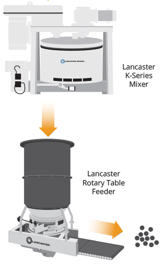
By making use of the improved structure according to this invention, the above difliculties and failings of this type of machine may be fully overcome. Consequently, feeders of this type in accordance with this invention, may be employed for a whole new field of materials that were formally not possible to feed in this type of machine. Feeders of this type generally, are used for many feeding operations, or similar uses, where it is important to obtain a predetermined and constant rate of feed of the material. Thus by using a rotary feeder of this type the bin or hopper may be periodically filled, or kept full, while the machine continues to operate and feed out the material contained in the hopper at a closely controlled rate. Feed rates can be precisely regulated in machines of this type by regulating the speed of, rota tion, and also by regulating the position of a deflector which removes the material from the edge of the rotating table.
It is an object of this invention to provide an improved type of rotary feeder, particularly for handling granular or freely rolling particles and which can feed granular and free rolling particles .at a controlled rate.
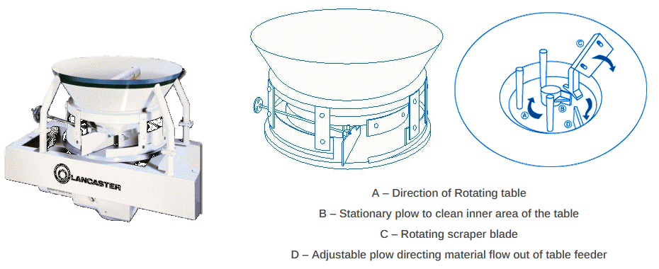
Another object of this invention is to provide a rotary feeder of a type wherein the material fed is supported on a table within a container, and where both table and container are rotated together. The improvements insuch a machine including certain configurations on the surface 2,896,824 PatentedJuly 28, 1959 feeder including a rotatable table, and side walls rotatable simultaneously with the table and spaced therefrom. The rotary feeder also including means for deflecting a predetermined amount of said material from within the said receptacle, off of the edge of said table. The invention being concerned with an improvement for a rotary feeder including the above elements; which improvement includes means on the surface of said table for restraining the said material from flowing freely off the table and being broadcast at random where said material has a very low angle of repose.
Fig. la is a fragmentary enlarged detail view in vertical transverse section showing the relationship between the table, the walls of the feed bin and the particles to be fed;
Referring to Fig. l, the principal elements of the feeder include a horizontally disposed table 11 which is supported by and securely fastenedto a vertical shaft 12. The shaft 12 is supported in its vertical position for free axial rotation, by a thrust bearing 13. Also supported by and firmly attached to the shaft 12, there is a cylindrical bin or hopper 16. The hopper or bin 16 is attached to the shaft 12 by a plurality of radially disposed rods or braces 17. These rods 17 may be attached to the side walls of bin 16 in any convenient manner, e.g. by riveting or welding. The rods 17 are fastened for lateral support from the shaft 12 by means of a collar 18 which fits snuggly over the shaft 12 and is fastened to the shaft 12 for positive rotation therewith in any convenient manner, e.g. by using a set screw or the like.
Near the bottom edge of the cylindrical side walls of bin 16, there is a band 21 that encircles the entire circumference of the bin 16 at the lower edge thereof. This band 21 provides for an adjustment of the clearance, or space, between the surface of the table 11 and the lower edge of the bin 16. Thus, the band 21 may be attached for vertical adjustment by any convenient arrangement, e.g. by employing vertical slots 22 in the band 21 and having machine screws 23 threadably attached to the walls of the bin 16 with the heads thereof projecting over the edges of the slots 22 in the band 21. Thus, by loosening the screws 23, band 21 may be slid vertically to vary the space between the lower edges of the band 21 and the surface of the table 11. The screws 23 will be tightened to maintain a given spacing when in use. v
The shaft 12 is rotated at a desired speed by any convenient drive connection e.g. by having a bevelled gear, such as shown at 26 in Fig. 3, attached securely to the shaft 12 below the table 1 1, and a pinion 27 meshing with the gear 26 for changing the direction of shaft axis at right angles. The pinion 27 is carried by, and is securely at tached to a shaft 28, for rotation therewith. The shaft 28 is driven in rotation from any convenient source of power, e.g. by having a belt drive connection with an electric motor 31 (as shown in Fig. l), which carries a pulley 32 on the shaft thereof. Belt 33 is used to produce rotation of another pulley 29 (as shown in Fig. 3), which is conveniently located on the shaft 28.
The supporting structure illustrated in Figs. 1 and 3 includes a framework 36 that supports a plate 37 which carries the motor 3 1 in an adjustable manner. Thus, in order to adjust the tension on the belt 33 an arrangement has been employed wherein the motor 31 is pivotally supported from the plate 37 by means of a pair of lugs 35 on the plate 37 and stud shafts 34. The adjustment is carried out by changing the position of motor 31 about its pivots (studs 34) by means of a threaded shaft 38 which is pivotally supported by an internally threaded hole through a block 40 that is carried on the plate 37. The shaft 38 has a hand wheel 39 at the extremity thereof for effectuating the desired adjustment.
On the surface of the table 11 there is a plurality of grooves 42. These grooves are spaced fairly close together. The particular spacing being determined by the material that is to be handled in the feeder. These grooves are spaced radially from inside the side walls of the bin 16, to the periphery of the table 1 1. The function of these grooves 42, as best shown in Fig. 1a, is to catch and hold particles of the material being fed through the space between the lower end of the bin 16 and the surface of the table 11 against radial displacement which would be caused by the natural flow of the material being fed and to a lesser extent by the centrifugal force when the table 11 and bin 16 are being rotated. In this manner, even though the particles of the material are hard and nodular or spherical in shape, they will be restrained from rolling freely across the surface of table 11 and consequently, no general broadcasting of the particles of material will occur.
A preferable arrangement for deflecting the material at a particular feed out point around the edge of the table 11 is that illustrated in Fig. 1 which includes a rotating cylindrical brush 45. Brush 45 may be caused to rotate in a direction generally opposite to the rotation of the table 11, so that the action with the bristles of the brush 45, tends to dislodge and sweep off all of the particles of material which are carried into the path of the brush (as the brush lies in contact with the surface of the table 11") during each revolution of the table 11. As the particles of material are deflected from their circular travel and swept off the edge of the table 11 by the brush, they may be directed to a particular location, for use as desired, by means of any convenient structure such as a chute 46. In order to provide for a more eflicient action of the brush 45, it is biased into contact with the surface of the table 11in any feasible manner. One convenient arrang"er"nentis that illustrated, wherein the brush 45 is driven in rotation by means of an electric motor 47. There is a change direction gear housing 48which provides a shaft rotation output at right angles to the shaft of the motor 47. Motor 47, along with its change direction gear housing 48, are mounted on a base 49 which in turn is mounted on the surface of a plate 50. The plate 50 is welded, or otherwise firmly attached, to an upright support angle 53. Thus, the aforementioned biasing for brush 45 is carried out by the weight of the motor 47, plus brush 45, by reason of the manner in which the motor is mounted, which includes a hinge 54. Hinge 54 has one part thereof fastened to the plate 50, while the other part is attached to base 49 of the motor 47. These mountings for motor 47 and plate t are set, so that there is clearance between the base 4Q: of
motor 47 and the surface of plate 50 when the brush 45 is in contact with the surface of the table 11. Consequently, the brush 45 is being pressed downward toward the surface of the table 11 by the combined weight of the motor 47 and the brush 45 attached thereto, acting about the pivot of hinge 54.
Satisfactory results have been obtained with a feeder, according to this invention, with a rotating bin 18 inches high and 15 inches in diameter and with a rotating table 21 inches in diameter. Using rotational speeds of from /5 r.p.m. to 14 r.p.m. and higher. A cylindrical wire brush 1 /2 inches in diameter and 4 inches long has been used; the axis of the brush being disposed "at a 45 angle to a radius of the table and bin. With the brush rotating at about 86 r.p.m. and the table and bin at /5 r.p.m., 1 /2 lbs. of copper shot was fed per minute. By adjustment of the table and bin rotation, the rate of feed was readily raised to 15 lbs. per minute. With the use of the brush, other types of metallic shot and nodules are effectively fed at controlled rates and the brush feeder has also been effective for various crushed granules such as carborundum, sand and quartz which cannot be effectively handled with ordinary scraper blades.
Effective retention of materials having a low angle of repose has been achieved with concentric grooves V of an inch deep and A of an inch wide with the grooves spaced about A of an inch apart. Other groove sizes are also useful and the size and spacing may be varied to obtain the most desirable results, with the matenals being handled. Spiral grooves, as well as concentric grooves, may all be used, and the grooves may be curved or V-shaped in profile or slightly raised ridges may also be found useful in achieving the purpose of providing means for retaining particles which would tend to flow out irregularly across the feed table at an uncontrolled rate. With the grooves, thematerial feeds out from the bin onto the table to substantially the same position around the table and stands at substantially the same angle of repose, particularly if the particles of the feed material are relatively the same in size and shape, so that the rate of feed can be accurately controlled and can be kept at an established rate.
Referring to Fig. 2, it will be obsenved, that there may be employed a means for cleaning the grooves 42 by dislodging any particles of the material being handled that are contained therein, as the table 11 is rotated. Such groove cleaning means might take various forms. The type illustrated includes a finger-like wire 55 located over each of the grooves"42. Eachwire 55 has the extremity or tip thereof spring biased into contact with the surface of the groove"42, by means of an integrally formed coil spring section 56. The wire 55 is supported firmly by being attached to a rod 59- that extends in a radial direction over the surface of the table 11. The wires 55 may be attached to the rod 59 in any convenient manner, e.g. by being press fitted into holes in the rod 59 as illustrated in Fig. 2. Rod 59is supported in any con- 1 venient manner (not shown) from the framework 36 desired. That is, it may be found more advantageous.
to locate the groove cleaning wires 55 behind the deflecting brush 45, so as to remove any particles which 7 have become lodged in the grooves and were not re moved by the action of the deflecting brush 45. However, in some instances, it may be found more advantageous to locate rod 59 so that the wires 55 are situated in front of the brush 45 inorder to loosen the particles from the grooves 42 just prior to their being deflected and swept off the edge of the table 1]..
In Fig. 3 there is illustrated a machine similar to that of Fig. l with the exception of the deflection brush 45 and its related elements. Consequently, the same reference numbers are employed for the same elements of the machine, but there is a deflector blade, 60 used instead of a brush. Blade 60 is pivotally attached to the top of the support angle 53 in any convenient manner, e.g. by having a machine screw 61 pass through a hole in the blade 60 and threadably engage a tapped hole in the top of the support 53. The blade 60 has a handle 62 for setting the position of the blade to determine how much of the material will be deflected by the blade during each revolution of table 11 and bin 16.
In Fig. 6 there is illustrated another embodiment of an improved deflector blade structure which includes a deflector blade 70 that has a plate 71 of flexible material attached thereto in such a manner as to extend out beyond the leading edge of blade 70. The plate 71 is set at an angle downward toward the surface of table 11, so that in use, the plate 71 rests in contact with the surface of the table 11. One satisfactory manner of attaching the plate 71 to the blade 70 is to employ a plurality of screws 72 for securely holding the plate 71 to the lower surface of the blade 70. The portion of the plate 71 which extends outward in front of the blade 70, is cut or slotted to form a plurality of teeth 73. In this manner, should any given scraper tooth 73 of the blade 70 become jammed, by reason of a hard particle wedging underneath the edge of the plate 71; such tooth may lift individually to release the pressure of such wedging action, without affecting the rest of the scraper teeth 73.
In Fig. 7 there is illustrated an embodiment of a rotary feeder according to this invention, that is designed for feeding relatively large quantities of material and which also may handle large sized particles The basic elements of the machine are the same as those described above in connection with the Figs. 1 and 3 embodiments. However, in this instance there is a framework 80 which includes a square or rectangular base 81, having at diagonally opposite corners thereof, a pair of upright support members 82. Support members 82 are held firmly flange or rim 97 around the periphery of the side walls of hopper 92. The bottom threaded portion of bolts 96 may be threadably received by lugs 98 that are conveniently attached to the skirt 93, as forex-ample by being welded thereto. The relative size of the apparatus will be appreciated from the fact that. the table 101 may be over 7 feet in diameter with the bin 92- about 8 feet tall and having a capacity of about 300 cubic feet.
At the lower end of the main supporting shaft 91 there is securely attached, for rotation therewith, a table 101. Table 101 has tapered braces 102 extending radially outward from a central hub 103 through which the shaft 91 passes. The rotational drive for shaft 91 and table 101, as well as hopper 92 therewith, is connected in any feasible manner, for example by employing a gear "105 at the lower end of the shaft 91, which has a pinion 106 meshing therewith. The pinion 106 is connected to a source of rotational power (not shown) by any convenient mechanical coupling arrangement, such as the change direction gearing 107 illustrated. At the lower extremity of shaft 91 there is a thrust bearing 108 for carrying the weight load of the table 101, shaft 91 and hopper 92; while providing the free axial rotation of the shaft 91. The thrust bearing 108 is firmly supported on the framework 80 by any convenient structure such as a base 109 that is attached to the base supports 81 of the framework 80. I
1. In a rotary feeder having a receptacle for material to be fed out at a predetermined constant rate including a rotatable table, side walls rotatable simultaneously therewith and spaced therefrom, and means for deflecting a predetermined amount ofsaid material from within said in position by diagonal braces 83, and across the top of the support members 82 there is a cross channel member 86. Fastened to the cross channel 86, for lateral support of the rotating elements of the machine, there is a bearing 87 that is held in place by a strap 88. Bearing 87 rotatably supports at the top thereof, a shaft 91 which carries attached thereto a cylindrical side walled bin or hopper 92. Near the lower edge of hopper 92 there is supported for vertical adjustment, a skirt 93. In this size machine, the vertical adjustment support for skirt 93 must be relatively rugged and strong. The arrangement includes a plurality of bolts 96 which pass through a receptacle off the edge of said table, the improvement comprising spaced groove means on the surface of "said table for restraining said material from being broadcast at random where said material has a low angle of repose.
2. In a rotary feeder having a receptacle for material to be fed out at a predetermined constant rate including a rotatable table, side walls rotatable simultaneously therewith and spaced therefrom, and means for deflecting a predetermined amount of said material from within said receptacle off the edge of said table, the improvement comprising groove means on the surface of said table for restraining said material from being broadcast at random where said material has a low angle of repose, said deflecting means including brush means cooperating with said groove means for dislodging said material from said groove means.
3. In a rotary feeder having a receptacle for material to be fed out at a predetermined constant rate including a rotatable table, side walls rotatable simultaneously therewith and spaced therefrom, and "means for deflecting a predetermined amount of said material from within said receptacle ofi the edge of said table, the improvement comprising concentric grooves on the surface of said table and cooperating with the said side walls to restrain said material from flowing off the table where said material has a very low angle of repose.
4. In a rotary feeder having a receptacle for material to be fed out at a predetermined constant rate including a rotatable table, side walls rotatable simultaneously therewith and spaced therefrom and means for deflecting a predetermined amount of said material from within said receptacle off the edge of said table, the improvement comprising concentric grooves on the surface of said table and cooperating with the said side walls to restrain said material from being broadcast at random where said material has a very low angle of repose, said deflecting means including counter rotating brush means cooperating with said grooves for dislodging said material from said grooves. r In a rotary feeder having a receptacle for material to be fed out at a predetermined constant rate including a rotatable table, side Walls rotatable simultaneously therewith and spaced therefrom, and means for deflecting a predetermined amount of said material from within said receptacle 011 the edge of said table, the improvement comprising concentric grooves on the surface of said table and cooperating with the said side walls of restrain said material from being broadcast at random where said material has a very low angle of repose, said deflecting means including counter rotating brush means cooperating with said grooves for dislodging said material from said grooves, means for biasing said brush means into contact with the surface of said table, means located over the edge of said table and adjacent to said restraining means for dislodging any material that becomes stuck in said restraining means. 7
6. In a rotary feeder having a receptacle for material to be fed out at a predetermined constant rate including a rotatable table, side Walls rotatable simultaneously therewith and spaced therefrom, and means for deflecting a predetermined amount of said material from Within said receptacle ed the edge of said table, the improvement comprising means on the surface of said table for restraining said material from being broadcast at random where said material has a very low angle of repose, said deflecting means including a curved blade located over the surface of said table and beneath said sidewalls for deflecting a predetermined quantity of material per revolution, means located over the edge of said table and adjacent to said restraining means for dislodging. any material that becomes stuck in said restraining means, said curved blade having greater clearance from the surface of said table at the trailing edge than at the leading edge thereof to prevent any build-up of caked material under the blade.
7. In a rotary feeder having a receptacle for material to be fed out at a predetermined constant rate including a rotatable table, side Walls rotatable simultaneously therewith and spaced therefrom, and means for deflecting a predetermined amount of said material from within said receptable off the edge of said table, the improvement comprising *rneans on thesur"face of said table for restraining said material from being broadcast at random where said material has a very low angle of repose, said deflecting means including a blade located over the surface of said table and beneath said side Walls for deflecting a predetermined quantity of said material per revolution, said blade having greater clearance from the surface of said table at the trailing edge thereof than at the leading edge in order to prevent any build-up of material under the blade.
8. In a rotary feeder having a receptacle for material to be fed out at a predetermined constant rate including a rotatable table, side walls rotatable simultaneously therewith and spaced therefrom, and means for deflecting a predetermined amount of said material from within said receptacle off the edge of said table, the improvement comprising means on the surface of said table forrestraining said material from being broadcast at random where said material has a very low"angle of repose, said deflecting means including a blade located over the surface of said table and beneath said side Walls for deflecting a predetermined quantity of said material per revolution, said blade having a flexible leading edge contacting the surface of the table, said leading edge being divided into sections to avoid lifting the entire blade should any material jam under the leading edge.
The hydrostatic rotary tables from ZOLLERN impress with their durability and a high concentricity and axial runout accuracy. Thanks to the ZOLLERN bearing clearance compensator, the optimal pocket pressure is set automatically and independently of production tolerances. The freedom from friction at low speeds prevents slip stick and therefore allows maximum positioning accuracy.
The Motion Index Drives RT Series Fixed Rotary Index Tables encompass a large range of sizes, ranging from our model RT100 up to our RT1250. In addition, special cam-driven devices can be custom made to order for your automation needs. RT Series Fixed Station Rotary Table are offered in a fixed number of stations or as a flexible turntable with a servo motor or standard AC brake motor with encoder. With the addition of Motion’s patented NANO Indexer Technology, the RT Series Fixed Station Rotary Table becomes the world’s most accurate barrel cam indexers.RT Series indexing tables are constructed with strength and reliability in mind. Robust design and components ensure this device will maintain precision in intense factory settings.

Conventionally, an apparatus including a rotary stand for placing an object thereon and rotating it, especially a roundness measuring machine that measures the roundness, concentricity, or coaxiality of an object to be measured, such as a cylinder or the like, has been widely used. A roundness measuring machine calculates the roundness of an object to be measured by detecting and collecting, with a probe or the like, surface position data on the object to be measured while rotating a rotary stand on which the object to be measured is placed. In order to measure the roundness, levelling needs to be performed to align the rotation shaft of the rotary stand with the central axis of the object to be measured. For this reason, the rotary stand generally includes an inclination adjustment means for levelling.
FIG. 10 shows the appearance of a roundness measuring machine including a rotary table 900 (corresponding to a rotary stand). The rotary table 900 includes an inclination adjustment means 902 for adjusting the inclination amount of a placement plane 901 in the X direction and an inclination adjustment means 903 for adjusting the inclination amount in the Y direction. FIG. 11 is a sectional view showing a detailed structure of the rotary table 901. The rotary table 901 includes a rotary base 904 rotatably supported by a rotation shaft 905 of a driving motor, a placement plane 901 supported so as to be movable and swingable on the rotary base 904 in the X and Y directions, and an X-direction inclination adjustment means 902.
The X-direction inclination adjustment means 902 includes a rotary knob 906 capable of feeding a spindle 907 rightward and leftward in the drawing. A base part 908 of the rotary knob 906 is fixed to the rotary base 904 via a connecting member 909. The tip of the spindle 907 is in contact with the side of a supporting part 910 of the placement plane 901 via an interlocking member 911. The interlocking member 911 is slidably supported by a supporting member 912, and the supporting member 912 is fixed to the rotary base 904. By operating the knob 906, the supporting part 910 moves rightward and leftward in FIG. 11 via the spindle 907 and the connecting member 909. Then, the relative contact position between an inclination ring 913 and the placement plane 901 changes. When, for example, the placement plane 901 moves rightward in the drawing (referred to as a pushing direction), the placement plane 901 is rotated and inclined in the counterclockwise direction against the biasing force of a tension spring 914 in the clockwise direction. On the other hand, when the placement plane 901 moves leftward in the drawing (referred to as a pulling direction), the placement plane 901 is rotated and inclined in the clockwise direction by the biasing force of the tension spring 914 in the clockwise direction.
The tension spring 914 in FIG. 11 causes, with its biasing force, the placement plane 901 to follow the movement of the spindle 907 when the spindle 907 is moved in the pulling direction. That is, the tension spring 914 pressurizes and holds the placement plane 901 so that the interlocking member 911 interlocking with the spindle 907 is always in contact with the supporting part 910. This holding force needs to be sufficiently high against an external force, such as the weight of an object to be measured placed on the placement plane 901, the inertia force generated when the rotary table 900 rotates, or the like. If the holding force is not sufficiently high against an external force, this causes the placement plane 901 to unexpectedly incline or oscillate. Especially, oscillation deteriorates the measurement accuracy. In addition, in order to accurately measure an object to be measured with large inertia and to quickly accurately position the rotary table 900, the holding force is preferably high.
However, to increase a pressure on the placement plane 901 and a holding force with a conventional structure means to increase the load on a feeder. The feeder is, for example, a screw-type feeding mechanism constituted by the knob 906, the spindle 907, the connecting member 909, and the like in FIG. 11. If, for example, a high-efficiency screw, such as a ball screw, is used, increase in a pressure can cause an undesirable phenomenon, such as reverse-starting of the screw. In addition, a motor drive mechanism can be used as the feeder, but increase in a pressure causes upsizing of the motor. Furthermore, increase in a pressure can cause deformation of the placement plane 901, and this can make an object to be measured placed unstably and adversely affect high accuracy measurement. Moreover, since a spring stretches and contracts according to an inclination amount and the elastic force varies with a conventional structure, an elastic force higher than the minimum force for holding needs to be generated. Thus, such a conventional structure easily causes the above undesirable phenomenon. Although decrease in a spring constant can avoid the problem, this generally requires a spring to be upsized and causes a layout problem.
The present invention has been made to solve these problems and is to provide a rotary stand capable of reducing the load on a feeder and deformation of a placement plane.
A rotary stand according to an embodiment of the present invention includes a feeder that adjusts an inclination of a placement plane, in which the feeder includes a first contact portion that interlocks with a feeding mechanism to move, and a second contact portion pressurized by a spring, and the first contact portion and the second contact portion disposed to face each other in the movement direction sandwich a held part interlocking with the placement plane.
In a rotary stand according to an embodiment of the present invention, at least one of the first contact portion and the second contact portion includes a self-aligning ball bearing, and the self-aligning ball bearing is in contact with the held part.
A rotary stand according to an embodiment of the present invention includes a feeder that adjusts an inclination of a placement plane, in which the feeder includes a contact portion that interlocks with a feeding mechanism to move and to be brought in contact with the placement plane, and a tension part pressurized by a spring and having one end connected to the placement plane, and an external force applied to the placement plane by the contact portion and an external force applied to the placement plane by the tension part are balanced.
According to the present invention, it is possible to provide a rotary stand capable of reducing the load on a feeder and deformation of a placement plane.
FIG. 2 is a perspective view (exploded view) of the structure of the rotary stand 100 according to the first exemplary embodiment of the present invention;
FIG. 3 is a perspective view (exploded view) of the structure of the rotary stand 100 according to the first exemplary embodiment of the present invention;
FIG. 4 is a sectional view (enlarged view) of the structure of the rotary stand 100 according to the first exemplary embodiment of the present invention;
FIG. 8 is a sectional view (enlarged view) of the structure of the rotary stand 300 according to the third exemplary embodiment of the present invention;
With reference to a sectional view in FIG. 1, perspective views (exploded views) in FIGS. 2 and 3, and a sectional view (enlarged view) in FIG. 4, a structure of a rotary stand 100 according to a first exemplary embodiment of the present invention is described. The rotary stand 100 includes a rotary base 30 rotatably supported by a rotation shaft 31 of a driving motor, a placement plane 21 supported on the rotary base 30 so as to be swingable, and a feeder 10 that adjusts an inclination of the placement plane 21 with respect to the X axis.
The feeder 10 includes a driven gear 11 that receives power from a motor 61 via a driving gear 62, a feed screw (ball screw) 121 that rotates with the rotation of the driven gear 11, a feed screw (nut) 122 that moves in the X-axis direction with the rotation of the feed screw (ball screw) 121, and sliders 123 and 124 combined with the feed screw (nut) 122. This mechanism for moving the slider 124 is referred to as a feeding mechanism 12. A pressurizing member 13 penetrates and is combined with the slider 124 so as to be slidable in the X-axis direction for a certain width. The slider 124 and the pressurizing member 13 are connected with each other via a spring 15.
In the present embodiment, the feeder 10 has the structure for holding the held part 23, and the spring 15 that pressurizes the placement plane 21 is disposed in this holding structure. Thus, it is possible to reduce the load on the feeder 10 and deformation of the placement plane 21. Accordingly, it is possible to increase a holding force with a pressure higher than a conventional structure.
Generally, a rotary stand includes a feeder for adjusting an inclination in the X-axis direction and a feeder for adjusting an inclination in the Y-axis direction. For example, the rotary stand 100 in the first exemplary embodiment is assumed to includes the held parts 23 and the feeders 10 for adjusting inclinations in the X-axis direction and the Y-axis direction, the held part 23 slides along the contact portions 14 and 16 in the Y-axis direction in the holding structure of the X-axis-direction feeder 10 when the Y-axis-direction feeder 10 drives. In addition, the held part 23 slides along the contact portion 14 and 16 in X-axis direction in the holding structure of the Y-axis-direction feeder 10 when the X-axis-direction feeder 10 drives. At this time, if a holding force is increased by increasing a pressure, the frictional force generated between the held part 23 and the contact portion 14 and 16 is also increased. Then, lost motion is generated and the accuracy of levelling can be deteriorated. This causes a problem, for example, that the inclination cannot be adjusted with desired accuracy or that the inclination must be adjusted a plurality of times. In the present embodiment, a mechanism for reducing the frictional force generated between the held part 23 and the contact portion 14 and 16 in the first exemplary embodiment is provided in order to solve the problem.
With reference to FIGS. 5, and FIG. 6 that is the A-A sectional view of FIG. 5, a structure of a rotary stand 200 according to a second exemplary embodiment of the present invention is described. Note that, the description of the structure common to that in the first exemplary embodiment is omitted. In the present embodiment, the rotary stand 200 includes, as a mechanism for adjusting inclinations in the X-axis direction and Y-axis direction, a feeder 10, a held part 23, and the like independently. In addition, in the present embodiment, the held part 23 is in contact with, instead of the contact portion 14 and the contact portion 16 in the first exemplary embodiment, a self-aligning ball bearing 141 and a self-aligning ball bearing 161.
For example, when the Y-axis-direction feeder 10 is operated, the held part 23, the self-aligning ball bearing 141, and the self-aligning ball bearing 161 move relatively in the Y-axis direction in the X-axis-direction feeder 10. At this time, it is possible to reduce the frictional force by rotating the self-aligning ball bearing 141 and the self-aligning ball bearing 161. In addition, when the X-axis-direction feeder 10 is operated, the held part 23, the self-aligning ball bearing 141, and the self-aligning ball bearing 161 moves relatively in the X-axis direction in the Y-axis-direction feeder 10. At this time, it is possible to reduce the frictional force by rotating the self-aligning ball bearing 141 and the self-aligning ball bearing 161.
With reference to FIGS. 7 and 8, and FIG. 9 that is the A-A sectional view of FIG. 7, a structure of a rotary stand 300 according to the third exemplary embodiment of the present invention is described. The rotary stand 300 includes a rotary base 30 rotatably supported by a rotation shaft 31 of a driving motor, a placement plane 21 supported on the rotary base 30 so as to be swingable in the X-axis direction and Y-axis direction, and a feeder 10 that adjusts an inclination of the placement plane 21. Note that, although the feeder 10 capable of adjusting an inclination in the X-axis direction is shown in the drawings, the rotary stand 300 may include the feeders 10 for adjusting inclinations in the X-axis direction and Y-axis direction as described in the second exemplary embodiment.
The feeder 10 includes a driven gear 181 that receives power of a motor 61 via a driving gear 62, a feed screw (ball screw) 182 that rotates with the rotation of the driven gear 181, a feed screw (nut) 183 that moves in the X-axis direction with the rotation of the feed screw (ball screw) 182, and a slider 184 combined with the feed screw (nut) 183. The slider 184 is in contact with a projecting part 22 via a self-aligning ball bearing 162.
In the present embodiment, it is possible to reduce the frictional force with the self-aligning ball bearing 162. Especially, in the third exemplary embodiment, by removing the pressurizing self-aligning ball bearing (the self-aligning ball bearing 141 in the second exemplary embodiment), the frictional force is halved compared to the second exemplary embodiment. The self-aligning ball bearing has a feature that the axes of the inner ring and the outer ring are inclined, and follows, utilizing this feature, the projecting part 22 (the held part 23 in the second exemplary embodiment) that inclines. Since the inclination of the axes of the inner ring and the outer ring is caused not by rotation but by sliding, a large frictional force is generated. For this reason, by changing the pressurizing mechanism from a self-aligning ball bearing to the wire 51, the frictional force at the pressurizing mechanism becomes almost zero, and more stable movement has been achieved in third exemplary embodiment.
This is a modification of our 4″ Manual Rotary Table. This modification came about after requests from our laser engraving customers. They wanted a rotary table that had a larger through-hole to which they could mount our chucks.
This version of the Sherline rotary table has a Nickel-Teflon plating on the tabletop because it was designed to be used in an everyday production environment. This gives the table a rust-resistant surface that is hard and has added lubrication qualities.
The table is 2″ high and 4″ (100mm) in diameter. The main components have been machined from solid bar stock steel, and the complete unit weighs seven pounds. The table has been engraved with a laser, giving sharp and precise lines every 5°, numbered every 15°. These lines are calibrated with the 72-tooth worm gear that is driven by the handwheel or stepper motor. The handwheel is divided into 50 parts, making each line on the handwheel 1/10°. This allows a circle to be divided into 3600 increments without interpolation. Seventy-two revolutions of the handwheel rotate the table one revolution.
NOTE: You can have your manual rotary table upgraded to CNC-ready, but this is done as a factory-only replacement. You will need to ship your manual rotary table back to our factory for the conversion.
PRECISION ROTARY TABLE Filed July 14, 1969 2 Sheets-Sheet 2 INVENTOR 17/?771? ED515727 ATTORNEY United States Patent 3,615,068 PRECISION RUTARY TABLE Arthur Edelstein, Jamaica, N.Y., assignor to Ardel Instrument Co., Inc., Jamaica, N.Y. Filed July 14, 1969, Ser. No. 841,417 Int. Cl. A47b 95/00, 91/00 US. Cl. 248-349 17 Claims ABSTRACT OF THE DISCLOSURE A precision rotary table for use in electro-optical research includes a stationary base member and a movable support part operatively connected to the base member and rotatable relative thereto. Precise positioning of the movable part in response to actuation of a manually operated means is effected by employing gearing mechanism in which the various rotating parts are continuously subjected to a constant force in a direction such that the meshing gears are placed in back-lash-free engagement with each other. An attachment device may be rotatably connected to the movable part, that device including mechanism which permits quick movement of the attachment device between two preselected positions.
A wide variety of rotary tables are currently used for research purposes. These tables are employed to rotate prisms, crystals, pol-arizers and the like to desired rotative positions. It is imperative in most applications that such positioning be carried out with great precision. Furthermore, it is extremely important that the rotary table be capable of repeatedly positioning the device with the same precision. Unfortunately, manufacturing tolerances which occur in the normal manufacture of the several movable parts in a rotary table render it virtually impossible to achieve a positioning :accuracy of better than a certain lower limit. Thus, far, increased accuracy in rotary tables of this type have been attempted by careful manufacture of the various parts, but even parts made by special techniques still include variations in dimensions which adversely affect the preciseness with which the device can be operated.
The subject invention provides a solution to the aforementioned difficulties by the inclusion of a means so positioned and structured that the various rotating parts in a rotary table are held under constant pressure in close contact with each other. In this manner, lost motion between the rotating parts is prevented and the accuracy of the rotary table is greatly increased.
Broadly, the rotary table of the invention comprises a stationary base member, a ring-like support part operatively connected to the base member and rotatable relative thereto, first means operatively connected to the support part for rotating the part, and means effective to continuously force the first means into a tight engagement with the support part during the operation of the device so that lost motion between these rotating members is prevented.
In one embodiment of the invention, the first means includes a pinion which is mounted on a shaft carried in bearings. The pinion meshes with a gear which is integrally secured to the support part and drives the part through the gear engagement. In the preferred embodiment a driving means for rotating the first means is included and comprises a worm afiixed to a second shaft and a worm wheel secured to the pinion shaft in a position to mesh with the worm. A manually rotatable means such as a knurled knob is secured at one end of the second 3,615,068 Patented Oct. 26, 1971 "ice shaft so that motion of the rotating components may be manually effected.
If properly located, the resilient member may provide still another force component along the axis of the pinion shaft. In the preferred embodiment this is accomplished by wedging the resilient member between a shoulder on the bearing and a flange on the base member, both the shoulder and flange being extended substantially laterally relative to the "aXis of the shaft and being spaced from one another substantially axially of the shaft. With this construction, the worm wheel and the pinion are axially positioned relative to their respective mating gears due to the resilient member being compressed axially in the space. In order to ensure the permanency of the gear location during the operation of the rotary table, the lower portion of the pinion shaft engages a non-resilient device such as a washer or the like, which rests on the base member. Still another resilient member may be placed below the lower bearing in order to provide a further radial force to the shaft so that additional radial pressure on the pinion and worm wheel may be provided.
Because a high degree of accuracy is desired, the manually rotatable means in the preferred embodiment is turned only one revolution for every arc degree traversed by the circular part. With this arrangement, the position of the circular part may be monitored at intervals of one are minute. However, it will be appreciated that with such a fine accuracy the manually operated means must be rotated many times for the circular part to traverse any considerable distance. Thus, if it is desired to rotate the table 90 turns will be required. Many times during the use of a rotary table such as in polarizer experiments, a particular angle must be repeatedly traversed. A rotary attachment device is therefore provided to enable the operator of the rotary table to repeatedly traverse a large distance in a short period of time. The attachment device is preferably mounted on the previously described rotatable part. It includes a lower element which is secured to the rotatable part and an upper element rotatably mounted on the lower element. The upper element functions as a rotary table itself once the attachment device is mounted in position, that is, it carries an optical device to a position along the arc of the circle over which the upper element is moved. Positive stops may be provided on the stationary base member and on the lower element of the attachment device between which the upper element of the attachment device is freely movable, thus providing for rapid but accurate positioning of that upper element in either of two predetermined positions. The rotative spacing between those positions can be accurately adjusted and varied by rotating the rotatable part of the device proper, which carries the lower element of the attachment device.
To the accomplishment of the above, and to such other objects as may hereinafter appear, the present invention relates to the construction of a rotary table device as defined in the appended claims, and as described in this specification, taken together with the accompanying drawings, in which:
Referring to FIG. 1, a rotary table is designated generally by the numeral or frame 10. The table 10 includes a base member -12 and a cover 14 secured to the base member by means of bolts 16. A ring-like support part 18 (on which the optical device or the like is adapted to be mounted) is rotatably positioned in one area of the cover 14, and includes a series of markings 20 which indicate in degrees the circumferential position of the support part 18. For this purpose an index pin -22 is mounted in the cover 14 and positioned adjacent the markings 20 .on the part 1-8. The cover "14 is also provided with a plurality of holes 24, continuing into base member 12, which may be used for mounting the table to a support. Holes 27 in the part 18 may be used for mounting other devices to hold prisms, crystals and other optical components. A large opening 25 is also provided in the central portion of part .18 so that the optical component may be rotated on its axis, that is, sothat light may enter from below the optical component. A manually rotatable member generally designated 26 includes a knurled knob section 28 and a section 30" which is provided with a plurality of index marks. The section 30 is positioned adjacent a bushing 32 fixed in base member 12 which is also provided with index marks. As illustrated more clearly in FIG. 2, the member 26 is spaced from the bushing 32 as shown at 34 and is rotatable relative thereto. In the actual operation of the device, the part 18 is driven in rotation by the rotation of the member 26. An indication of the specific amount of movement is obtained by reading the position of part 18 at the markings 20 and the position of the markings on section 30, the latter constituting a Vernier or fine indication and the former constituting a coarse indication.
The coupling mechanism between the manually rotatable member 26 and the part 18 is more clearly illustrated in FIG. 2. As there shown, the member 26 is tightly connected to a shaft 36 by means of a screw 38. The connection between member 26 and the shaft 36 is a rigid one since it is highly desirable that there be no motion between these parts when the member 26 is rotated. Worm 40 is pinned to shaft 36, and is constrained axially of the shaft 36 by spring washer 41. Worm 40 in turn meshes with worm wheel 42. The worm wheel 42 is mounted on a shaft 44 (see FIG. 4). The pinion gear 46 is also securely mounted on shaft 44 directly above the worm wheel 42. The ring-like part 18 is integrally formed with a gear 48, which meshes with and is driven by the pinion 46.
It has been determined that a preferred gear reduction ratio between the part 18 and the manually rotatable member is in the order of 360:1. In one embodiment, the gear ratio between gear 48 and the pinion 46 may be 12:1, while the ratio between the worm wheel 42 and the worm 40 is approximately 30:1. With this high ratio, one turn of the member 26 will move the circular part 18 only one arc degree. The index marks on the section 30 of the member 26 can therefore be graduated to increments of as low as one are minute, which is lower than most precise devices currently in use.
FIGS. 6 through 8 illustrate a rotary attachment device 86 which may be mounted on the rotary table device 10 shown in FIG. 1. Referring to FIG. 6, it will be seen that the attachment device is generally designated by the numeral 86 and comprises a lower part 88 which is secured to the inside surface of the gear 48 by means of a set screw 90. An upper part 92 is operatively connected to lower part 88, and is rotatable relative thereto. In order to effect the rotation a plurality of bearing balls 94 are interposed between the parts 88 and 92, the balls sliding in the V groove 96 in part 88 and are secured in position by set screws 98 in part 92. A projecting tab 100 is secured to the upper rotary part 92 by screw 102. A similar projecting tab 104 is secured to the stationary part 88 by means of screw 106. This tab 104 is provided with an extending button 108 which projects upwardly a distance such that it extends into the path of movement of projecting tab 100.
FIGS. 7 and 8 illustrate by means of plan views the relative positions of the several tabs 100 and 104 during the operation of the device. As shown in FIG. 7 a stop member 110 is pressed into the cover 14 on the rotary device 10 and extends upwardly therefrom. The tab 100 is initially positioned in contact with stop member 110 and the tab 104 is positioned initially such that the extended button 108 engages the edge 112 of the tab 100. This alignment of members represents the starting position for the device. Since tab 104 is fastened to the stationary part 88, and the stationary part 88 is fastened to the gear 48 on the rotary device 10, the manually operated member 26 controls the position of the stationary part 88. Therefore, when the member 26 is rotated part 88 is carried with part 18 to a desired position. The tab 104 is carried with part 88 while the part 92 and its tab 100 are also rotated to the new position. The new position is illustrated in FIG. 8, and by way of example represents a 90 movement of the parts 18 and 88. This position is marked by the extended button 108. As noted, the tab 100 and the upper part 92, to which it is affixed, are rotatable relative to the lower part 88 and the tab 104 which is connected to it, and are shown after rotation back to stop 110. Thus, if the optical device which is to be positioned is joined to the attachment device 86 after the desired position represented by the position of button 108 is achieved, then the optical device can be accurately and quickly rotated 90 by rotating tab 100 and part 92 between the button 108 and stop member 110, those elements representing two accurately positioned stops between which an optical device may be quickly and repeatedly maneuvered with no sacrifice in accuracy.
From the foregoing it will be appreciated that a rotary device of the invention is capable of precise positioning of an optical device or the like about an arc of 360. The prevention of lost motion between rotary parts enables the rotation to be effected with an accuracy heretofore not readily achieved. In addition, an attachment device enables any position to be accurately repeated without the necessity of tedious manipulation of the various parts.
1. A rotary device effective for precisely locating a rotative position comprising a frame, a support part operatively connected to said frame and rotatable relative thereto, first means operatively connected to said support part and said frame for rotating said part, said first means comprising at least two rotatable means operatively connected in driving relationship, and forcing means effective to apply a pressure on at least one of said rotatable means in a direction perpendicular to its axis of rotation to forcefully maintain driving engagement between said rotatable means during the operation of said rotary device, such that there is substantially no lost motion between said rotatable means during the operation of said rotary device even after considerable wear of the meshing gear surfaces.
2. The device of claim 1, in which said rotatable means comprises first and second gearing means operatively connected to said support part and said frame respectively, said forcing means being effective to positively maintain said first and second gearing means forcefully meshed in operative driving engagement.
3. The device of claim. 2, wherein said first gearing means is fast on said support part and said second gearing means is fast on a shaft, means rotatably mounting said shaft on said frame, said forcing means comprising means disposed between said shaft and said frame and effective to apply a positive radial pressure on said rotatable mounting means in a direction to forcefully mesh said second gearing means with said first gearing means.
5. In the device of claim 3, driving means for rotating said second gearing means, said driving means comprising third and fourth gearing means operatively meshed together, said third gearing means being fast to said shaft and said fourth gearing means being operatively drivingly connected to a manually rotatable member, whereupon when said manually rotatable member is rotated the rotative motion thereof is transmitted to said support part to rotate the same, said forcing means being effective to simultaneously apply a pressure to said first and third gearing means in a direction to forcefully maintain them in operative meshing engagement with said second and fourth gearing means, respectively, during the operation of said rotary device, whereby lost motion between said first and second gears is substantially prevented.
11. In combination with the device of claim 1, a rotary attachment means comprising a lower part secured to said support part, an upper part operatively connected to said lower part and rotatable relative thereto, and a tab extending outwardly from said upper part on said attachment device, said tab on said upper part being movable to a specific position by the movement of said upper part relative to said lower part, and a stop element carried by said lower part toward which said upper part tab is movable and with which said upper part tab is engageable.
17. In a gear train for a precision rotary device having 7 a frame, a member rotatably mounted in said frame, and an adjusting means for adjusting the rotary position of said rotatable member on said frame, a first gearing means in operative driving relationship to said rotatable member, a shaft rotatably mounted in said frame in operative driving relationship to said adjusting means, a second gearing means mounted fast on said shaft, a resilient bearing member disposed between said shaft and said frame, said resilient member being compressed against said frame as a result of the operativemeshing engagement of said first and second gearing means, thereby forcefully to maintain said operative meshing engagement even after considerable wear of the meshing gear surfaces.
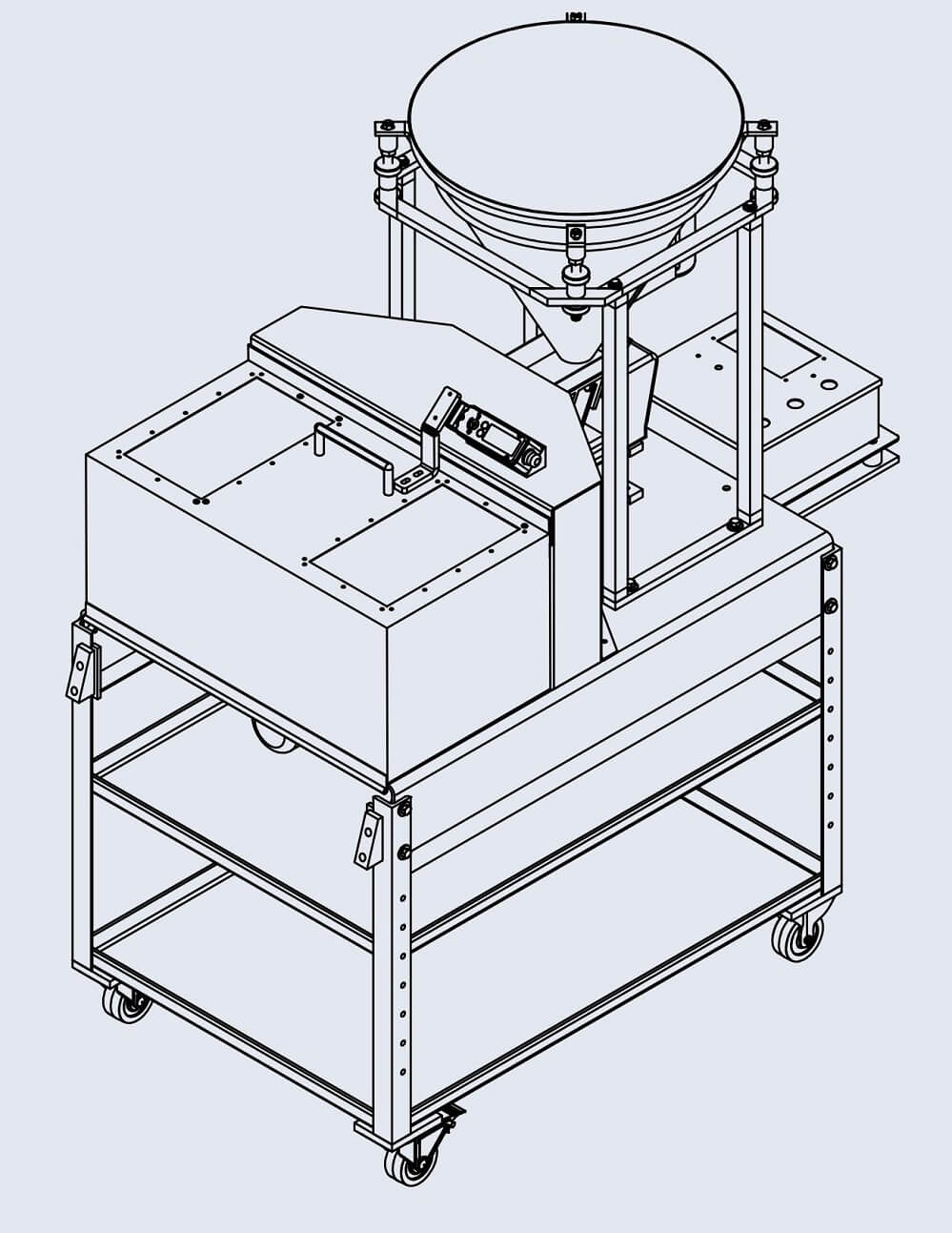
This bench-type rotary sample splitter is supplied with two variable speed drives. The rotary table has a motor that will rotate from 0 to 53 revolutions per minute. The vibratory feeder motor will give you 0 to 11 feet per minute. Upon the gravity flow and vibrator agitation from the feeding hopper, you will be able to achieve the desired splitting ratio by adjusting speeds of the vibratory feeder and the rotating table. See setup instructions on the following pages for details.
Turn the carousel on and use the dial on the control panel to adjust the carousel rotating speed minimizing dust and particles flying out as material falls into the containers. Use good judgment to establish a suitable speed as you observe the way material falls.
Before turning on the vibrator feeder, fill the hopper with test material. To prevent dust and overflow when loading the hopper with very fine material, pour a small amount in first to fill the opening at the bottom before pouring in the entire sample.
With the carousel rotating, turn the vibrator feeder on. You should begin to see material moving from beneath the hopper on to the tray. The vibrator feeder also has a variable speed control to adjust the speed at which material flows. Turn the dial to a point where you are satisfied with the rate of flow. You may want to re adjust the hopper height at this stage if material is flowing too fast, too slow or clogging.
Some machines are supplied with a vibrator on the hopper to prevent clogging at the output and sticking of material to the inside. This is not adjustable, simply turn it on or off and take note of the effect it has on the way material flows. Not all material requires that the hopper vibrator be turned on.
In order to safely achieve accurate and repeatable results, it is critical that you follow the operating procedure below. Refer to the setup instructions on page 3 before you begin running samples.Place all of the collection containers on the carousel tray and ensure that they are seated properly within the carousel edge. For machines supplied with reject collection capability, make sure the containers are properly hooked on the rotating carousel in the center.
Note: It is imperative that the carousel motor dial, vibrator feeder dial, and hopper vibrator switch are not touched while splitting occurs, as this will cause inaccurate results.


 8613371530291