
4th axis rotary table for vmc free sample

Heavy, What ever you decide try to keep the configuration "Industry Standard". Vertical CNC "A" rotates about "X", Horizontal CNC "B" about "Y". You will find that the mpmaster post will work right out of the box for you. Also the "Right hand Rule" applies to this standard as well. I"ve worked in places where the Rotary Axis"s were mounted wrong and the post"s had to be butchered up to output code that would work. I recently heard that one place that did it this way won"t use MCX because their post"s from V9 won"t import to MCX and work properly so they threw in the towel right away. They are set in their ways and won"t consider changing to the "Standard" or fixing the post"s to do so. Funny because one guy that has been there since the beginning and has never worked in another shop is the one guy who is holding them back. First thing I noticed when I ran my first rotary axis program thru his "Bullet Proof Post" was that the "A" axis code was off by 180°. He told me I had it set up wrong in MC because I was looking at the part from the Spindle"s perspective. I said that"s the norm and he said "Not here it"s not" No point in arguing if that"s the way they want to keep doing things but it ain"t right. Anybody agree or disagree?

A rotary table is a workbench, designed to cut wood, metal, and other surfaces with a built-in tablebench, to make work easier. It is so compact and easy to use as a 4th axis tablebench, so that the work can be harder.
There are many types of rotary tables depending on your client"s needs. The rotary table is also called a rotary table, if it is a client"s design or a business, it can be compared to other rotary tables depending on the client"s needs. A rotary table is also called a rotary table, which allows users to cut many projects at once and have a different finish compared to the original rotary table.

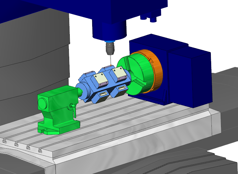
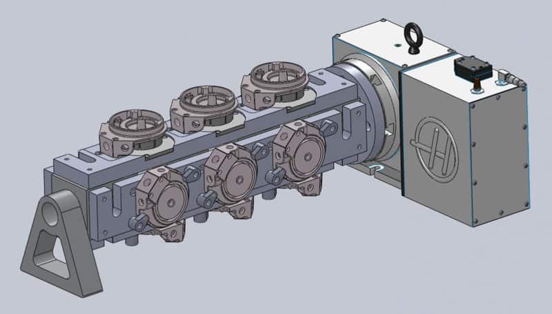
With this extension, your CNC milling machine gets the 4th axis. That allows you, for example, to mill round parts or create engravings on rounded surfaces.
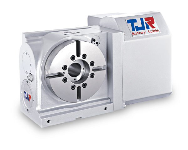
This rotary axis is made to order for us by a German precision mechanic. In this price segment, this rotation axis for CNC milling machines is unrivalled in Europe!
There are many rotary tables on the market. If possible, they have to be inexpensive. You can get a lot of them! Usefulness? That is where the wheat is separated from the chaff. For example, there are many CNC turntables with the cheapest belt transmission. The disadvantages are obvious: slippage due to the belt. If not in the belt drive itself, then on the load or idle side of the belt. Perhaps useful for engraving work. For milling, however, usually not or limited in the choice of material (aluminium 3D milling not possible).
That means you can use the CNC router for 3D 360° machining in almost all materials. Even round engravings on Plexiglas are possible without any problems with this CNC accessory. That means for our CNC machine users: Round surface milling of plastic parts, wooden parts, aluminium parts or round parts made of brass, as well as engravings of all kinds.
This website or its third-party tools process personal data (e.g. browsing data or IP addresses) and use cookies or other identifiers, which are necessary for its functioning and required to achieve the purposes illustrated in the cookie policy. To learn more, please refer to the cookie policy. In case of sale of your personal information, you may opt out by sending us an email via our Contact Us page. To find out more about the categories of personal information collected and the purposes for which such information will be used, please refer to our privacy policy. You accept the use of cookies or other identifiers by closing or dismissing this notice, by scrolling this page, by clicking a link or button or by continuing to browse otherwise.
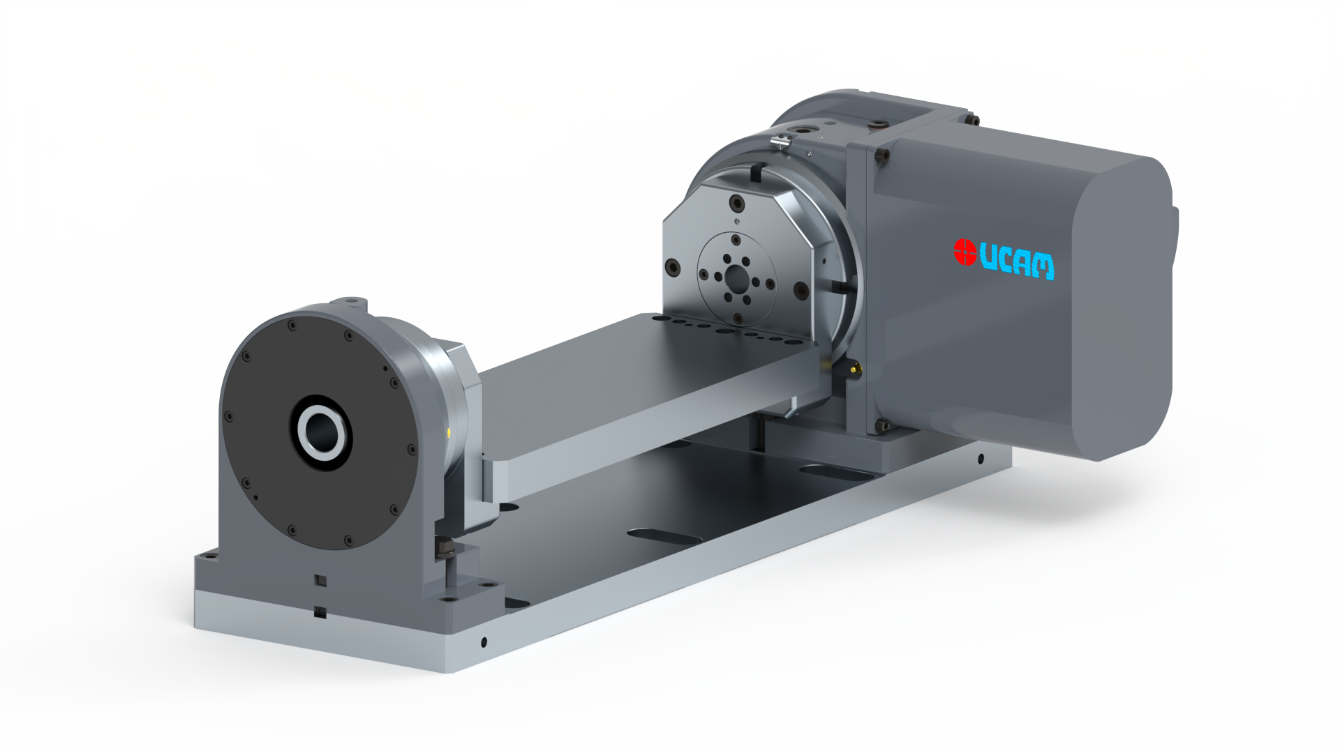
With modular design concept and engineering, Rotary Production Systems have continued to support and succeed at applications which demand high volume productivity.
We offer a wide range of CNC Rotary Tables and custom-built rotary tables which can be used vertically and horizontally based on the application. Our differentiation lies in cutting-edge technology, unceasing product innovation, and proactive customer relationship, making UCAM the most preferred brand in the Indian machine tool industry. UCAM"s product line lays stress on quality, reliability, and performance while machining the needs across industries - Automobile, Aerospace, Medical, Mining, Defence, Power Generation, General Engineering and Others

The robust geared rotary tables of the 500 series are extremely flexible to use and, thanks to the combiFLEX® modular system, can be converted or extended at any time to meet new machining tasks. The rotary tables are not only suitable for positioning operation, but can also be used for short simultaneous machining operations. The preloaded gear and the powerful bearings allow high long-term accuracies as well as large spindle loads. The maximum clamping force of up to 7,000 Nm leaves hardly anything to be desired.
The largest B type model from Nikken with motor mounted to the rear, with higher gear ratio over earlier models increases speed over the vertically mounted motor version type CNC-400V. This unit also has a hydraulic clamping system. The unit has a 130mm spindle nose location with a location depth of 12mm with 105mm directly through the table and a has a centre height of 230mm in the vertical position. This device in the first instance is a vertical mount only device with options for a side mount motor, version which can be found under product code CNC-400V. An excellent carrying capacity of 250kg vertically unsupported and 500kg between centres with a standard tailstock with rotation speeds up to 22. 2rpm dependent on motor selection. (example given is with a 2000rpm motor)Net weight of this device is around 280kgThe Nikken CNC-401B rotary table is offered without motor and can be prepared to suit any interface at additional cost (see our interface listings for details and costs for “external interface”) (motor, switch, cable and connector requirements if you already have a “4th axis interface” in the machine) and machine interface costs (if you do not have the additional axis fitted). Motor is mounted to the rear via the right hand side on this device and is designed to avoid restriction to the Y axis capability and with a large bore available should you want to machine long bar components that need to be mounted through the centre. Please remember however, that being a back mount device the centre bore is restricted to passing through only the depth of the casting (240mm)This range of Nikken devices have Tungsten carbide worm shafts and hardened wheels which can mean less backlash adjustment required over a conventional brass/bronze standard gear.

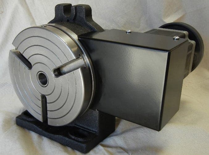
Sherline’s CNC driver box comes equipped with an A-axis output cable ready to drive a 4th rotary axis. This rotary table is all you need to turn your Sherline CNC mill into a 4-axis machine. Just plug the A-axis cable from the external driver box or the built-in driver box in your Sherline computer into the matching plug on the stepper motor. The EMC2 software is already set up to handle G-code for the A-axis, and numbers entered after the letter “A” in your code are interpreted in degrees.
The same end result can be obtained by ordering a CNC ready rotary table and a stepper motor and attaching the motor, but this single part number does the same thing, making it easier to order and saving you the trouble of installing the motor on the rotary table.
Sherline has taken its P/N 3700 manual 4″ rotary table and applied a stepper motor mount with dampened coupling in place of the handwheel. The mount accepts a NEMA #23 frame-size stepper motor for CNC control. This allows the table to be used as a 4th axis with CNC systems that have the capability to drive a rotary axis.
The rotary tables can hold more weight when they are not under a continual load. Click on the Video tab above to see examples of different weights and uses for our rotary tables.
This website is using a security service to protect itself from online attacks. The action you just performed triggered the security solution. There are several actions that could trigger this block including submitting a certain word or phrase, a SQL command or malformed data.

While 3-axis milling is widely used across the industry, operators have incorporated a fourth axis for complex design production. This additional axis enables machining wrapped features, turning, and contouring in a variety of applications, and is compatible with a variety of CNC machinery arrangements, boosting its versatility. Let’s explore the merits of 4-axis further, looking especially at its role in mill-turning.
Turning involves any process where the workpiece (the piece of secured, pre-shaped material) rotates in a chuck while the cutting tool moves across it. During this machining process, the material is removed from the workpiece, creating a revolved profile. While milling employs multipoint tools and a fixed workpiece, turning typically uses single-point tools. Mill-turning combines the revolution of the workpiece with the tools of milling. This combination facilitates greater manipulation of the workpiece, like rotation, allowing for more intricate milling patterns.
The typical 3-axis setup includes the X, Y, and Z axes. The 4-axis will depend on the machine configuration. For mill-turns it is commonly the “C” axis, and it rotates around Z. In milling machines with a rotary, it is commonly the “A” axis, and it rotates around X. In any configuration, the fourth axis is the rotary axis, meaning it rotates around one of the other axes, adding much more flexibility and control when manipulating the workpiece. Various tools can be attached to the fourth axis to expand output capabilities.
A fourth axis aids manipulation and accuracy of your milling tool. 4-axis is critical for cutting features along an arc when manually machining, which is otherwise difficult to do. This process is often referred to as continuous cutting. Capable CAM software is necessary when automating this continuous machining process, as it is more complicated. But what if we want to fix this axis?
When the fourth axis is used for indexing, the axis is locked while the cutting tool executes moves in 2- or 3-axes (X, Y, Z). Indexing is often called 3+1 because all 4-axes are not moving simultaneously. Indexing is a simpler process than continuous operation and is excellent for gaining improved access to the parts being manipulated. It might reduce the number of setups needed to machine a part, significantly improving total cycle time. This additional axis allows for much higher efficiency and greater flexibility.
Due to the complexity of continuous 4-axis work, software is often implemented to simplify the programming process. While standard 2- and 3-axis strategies are used during indexing, these programmed solutions aren’t adequate for more complex 4-axis operations. A simple way to accomplish this is through 4-axis wrapping software, which transforms 2D and 3D strategies to wrap around a cylinder. It is easy to start with XYZ plane programming and convert it to accommodate the fourth axis.
Simultaneous 4-axis basically requires full-fledged CAM software. These programs go beyond g-code wrapping, allowing for rotation of the fourth axis while the other three axes are also in motion. CAM software, such as Fusion 360, will enable teams to program wrapped toolpaths, simultaneous 4-axis motion, and even an array of parts in tombstones.


 8613371530291