
apex rotary table free sample
Rotary turntables play an important role in the automation and profitability of the filling process. At higher rates of production, many automated machines only work at peak efficiency when bottles are moved along via a conveyor belt while also being lined up side-to-side with no gaps. For example, a piston filler with multiple heads would miss the bottles that had to be filled and were not positioned precisely. This same careful positioning is also needed for any machine that is designed to handle more than one bottle at a time.
Without aloading rotary turntable, an individual worker would need to constantly load up a long-enough backlog onto the conveyor belt to maintain a steady feed of bottles through whatever machine is being used – such as a filler, capper or labeler. In addition, the bottles would have to be spaced neatly by hand, which would further slow down production. With a loading rotary turntable in place, however, one person can add a large number of containers to the turntable at once and allow the machine to move them evenly onto the conveyor belt. That person can then work on other things in-between reloading the turntable.
Accumulating rotary turntablessafely gather up the bottles once they have passed through the machine. Without them, production would have to be stopped frequently before the containers reached the end of the conveyor belt, especially if they are made of fragile materials. The rotating table can also collect many bottles streaming in without the risk of them bunching up and tipping over, as may happen if the conveyor belt ended at a non-rotating tabletop. As the accumulating rotary turntable starts to fill up, the bottles can be removed and packaged while more containers continue to be processed.
When the bottles are placed on the loading rotary turntable, the steady rotation of the surface brings them into contact with either the guide rail along the outer edge, or the flexible bottle guide that extends from the center of the disk to nearly the outer edge, forming a narrowing angle. When a batch of containers is too large to fit through the gap between the guide and the rail, the extra bottles either travel around the inner portion of the disc until they are guided by the strip again, or the bottles slightly widen the gap as they pass through it. With repeated rotations, the bottles are soon lined up neatly along the outer edge of the turntable, ready to be moved onto the conveyor belt in single file.
The process is echoed at the end of the production line as the containers make their way to the accumulating rotary turntable. When the bottles leave the conveyor belt, they pass onto the turntable in a smooth line that goes around the outer edge, held in by the rails. As more bottles come onto the turntable, the movement and the guides work together to move the bottles closer to the center until most of the surface area is filled and the bottles can be removed for packaging or for another stage of the filling process.
These turntables can be an end point of the filling process, or they can hold containers that are being conveyed between two different stages of packaging.
Our team at Apex is available to discuss all aspects of your filling system and advise you on what components would best serve the needs of your company. Call us at 219-575-7493 orvisit our page hereto discuss the best equipment choices for you.
Integrity, honesty, and a dedication to delivering ambitious results serve as the central themes of Alicia’s career and are evident in every interaction she has with our clients. Her relationship-centered leadership style has paved the way for Apex Filling System’s culture of compassion & empathy, executed with accountability that ensures consistently great outcomes.
As a learner for life, her pursuit of continuous personal and professional growth has led Apex Filling Systems to be recognized as an industry innovator in customer experience. Holding advanced degrees in the areas of engineering and management, she has a unique ability to analyze processes, identify potential problems before they arise, and develop standardized solutions to ensure every client of Apex Filling Systems enjoys a hassle-free, professional, and pleasant experience.

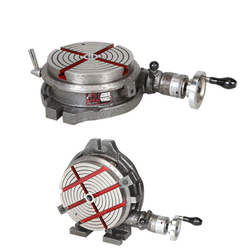
APEX ROTARY TABLES have a sturdy design to suit many machining operations on Milling Machines including circular cutting, setting angles and indexing. They are available in a range of sizes to suit various machines and machining applications.

The present invention relates to apex seals for rotary piston engines and more particularly to apex seals of such materials that have both wear-resistant and shock resistant properties.
Conventional rotary piston engines comprise a casing which includes a rotor housing having an inner wall of trochoidal configuration and a pair of side housings gas-tightly secured to the opposite sides of the rotor housing to define a rotor cavity of trochoidal configuration. In the rotor housing, there is rotatably disposed a rotor of polygonal or usually a triangular configuration. The rotor includes a plurality of apex portions which are adapted to slidably engage the inner wall of the rotor housing so as to divide the rotor cavity into a plurality of working chambers having volumes which vary in response to the rotation of the rotor.
In order to provide a gas-tight seal across the adjacent working chambers, the rotor is provided at each apex portion with a so-called apex seal. For the purpose, each apex portion of the rotor has an axially extending seal groove in which an elongated seal is received. The seal is resiliently biased against the inner wall of the rotor for sliding engagement therewith and moves along the inner wall of the rotor at a substantial speed as the rotary engine is operated. Thus, the apex seal must be of a highly wear-resistant material which is also durable to heat applied by engine combustion gas and produced in the seal due to the friction between the apex seal and the rotor housing wall.
Further, the apex seal is also subjected to cyclic impact loads in use. Since the apex seal is used for gas-tightly separating two adjacent working chambers, when combustion takes place in one of the working chambers, the apex seal is forced under the pressure of combustion gas toward one of side walls of the seal groove in the rotor. As the rotor further rotates, combustion takes place in the other working chamber so that the apex seal is then forced toward the other direction under the pressure of combustion gas in said other working chamber. Thus, the apex seal is cyclically bumped against the side walls of the apex seal groove and therefore it is subjected to cyclical lateral impact loads of substantial value. Further, the movement of the apex seal is such that it is not always in close sliding contact with the inner wall of the rotor housing but cyclically moved away from the inner wall under the inertia force and again brought into bumping engagement with the inner wall under the biasing force and the centrifugal force on the apex seal. This movement of the apex seal causes cyclic impact loads thereon.
Therefore, it will be understood that the apex seal should desirably be made of an impact and wear resistant material, however, it has been practically difficult to obtain a material which is satisfactory in respect of both impact and wear resistant properties since an improvement in the impact resistant property has generally caused poor wear resistant property. For example, proposals have been made of providing apex seals by a sintered alloy containing substantial amount of carbides such as TiC or by a cast iron containing high percentages of boron. Such apex seal materials have been found as possessing a satisfactory hardness as well as a superior wear resistant property, however, it does not have an adequate impact resistance. Therefore, in the known apex seals of the type that are made of the aforementioned materials, impact resistance has been provided by increasing the dimension, that is, the height and the thickness of the seal. However, such increase in the dimension of the apex seal is not recommendable from the view point of engine performance because any increase in the mass of the apex seal causes an increase in the sliding drag.
There has also been proposed by Japanese patent application Sho 50-12142 which has been disclosed for public inspection and at the same time published in Japanese Patent Gazette on July 30, 1976 under the disclosure number of Sho 51-87117 to provide an apex seal by a totally chilled cast iron. According to the proposal, the apex seal is made of a totally chilled iron-based material containing in weight 2.5 to 2.8% of total carbon, 1.5 to 3.0% of silicon, 0.5 to 1.0% of manganese, less than 0.30% of phosphorus, less than 0.10% of sulphur, 0.3 to 1.0% of chromium, 0.4 to 1.0% of molybdenum, 0.4 to 1.0% of nickel or copper, 0.02 to 0.10% of boron and the balance of iron. However, this type of apex seal has been dissatisfactory in respect of wear-resistant property.
It has also been proposed by the U.S. Pat. No. 3,658,451 to provide a layer of chilled structure only in the sliding surface of an apex seal. In this type of apex seal, the wear-resistant property is provided by the layer of the chilled structure while the impact resistant property is provided by the basic cast iron material. The proposed apex seal is advantageous in that both of the wear resistance and the impact resistance can be provided without increasing the dimension of the seal. However, this type of apex seal has been found disadvangeous in that it comprises two layers of different coefficient of thermal expansion so that it is deformed under the heat produced in the engine operation and cannot maintain a line contact with the inner wall of the rotor housing throughout its length. Such deformation of the apex seal causes pressure leakage from one working chamber to another. Further, local non-uniform contact of the apex seal with the inner wall of the rotor housing may cause scratches therein possibly damaging the chromium plate layer on the rotor housing inner wall.
It is therefore an object of the present invention to provide a material for apex seals of rotary piston engines which possesses both wear-resistant and impact resistant properties.
Another object of the present invention is to provide apex seals for rotary piston engines which are satisfactory in respect of sealing property and do not have any adverse effect on the engine performance.
A further object of the present invention is to provide apex seals for rotary piston engines in which the aforementioned disadvantages of prior art have been overcome.
According to the present invention, the above and other objects can be accomplished by an apex seal for rotary piston engines which is made of an iron-based material containing in weight 2.5 to 4.0% of C, 0.5 to 2.8% of Si, less than 1.0% of Mn, 0.25 to 2.0% of Ni, 0.25 to 2.0% of Mo, 0.25 to 2.0% of Cu, 0.15 to 0.4% of B, 0.15 to 1.5% of Cr, 0.1-0.4% of V and the balance of substantially iron, said material being of chilled structure throughout the apex seal. Said material may contain impurities such as phosphorus and sulphur. The chilled structure is provided simply through casting of the material without any specific cooling means.
Although there is a decrease in the impact resistance due to the boron content, such decrease is compensated for by addition of Ni, Cu, Mo and V. The boron content has been known as having a significant effect on the promotion of producing chilled structures but having a tendency of making the structure brittle. The V content has, when added by a suitable amount, an effect of producing fine chilled structures which contribute to improve the ductility.
Thus, according to the present invention, an uniform chilled structure can be obtained throughout the body of the apex seal simply by casting the material without using any cooling means. It has been found that the chilled structure in accordance with the present invention has a wear resistance which is fifty percent higher than that obtained by a conventional apex seal made of an acicular cast iron having a chilled sliding surface. Although the apex seal has a chilled structure throughout the body thereof, it has also been found that the impact resistance thereof is fifty percent higher than that obtained by a conventional apex seal because the apex seal of the present invention has a fine structure and added with Ni, Cu and Mo. It will thus be understood that the apex seal of the present invention is made of a material which possesses both the wear resistant and the impact resistant properties. According to the present invention, therefore, it is not necessary to increase the dimension of the apex seal for the purpose of providing an adequate impact resistance. Further, it is possible to eliminate any thermal deformation. As the result, the apex seal in accordance with the present invention can provide an improved sealing property which contributes to an increase in the engine output as well as an improvement in fuel consumption. The fact that the apex seal has a uniform structure throughout the body thereof is effective to eliminate any thermal deformation. Moreover, since the apex seal has a chilled structure throughout the body thereof, the coefficient of thermal expansion is very small so that the thermal expansion of the apex seal can be maintained very low. This fact also contributes to the improvement of the sealing property.
FIG. 4 is a diagram showing the brake mean effective pressure and the brake output in a rotary piston engine equipped with apex seals in accordance with the present invention as well as those in a rotary piston engine equipped with conventional apex seals; and
FIG. 5 is a diagram comparing the fuel consumption in a rotary piston engine equipped with apex seals in accordance with the present invention with that in a rotary piston engine having conventional apex seals.
Referring to the drawings, particularly to FIGS. 1(a) and (b), the rotary piston engine shown therein includes a casing C which comprises a rotor housing R having an inner wall 4 of trochoidal configuration and a pair of side housings S secured to the opposite sides of the rotor housing R. In the casing C, there is disposed a rotor 2 of triangular configuration. The rotor is formed at each apex portion with a groove 3 in which an apex seal 1 is received. The apex seal 1 is biased radially outwardly by means of a spring 8 which acts on the apex seal 1 and a wedge-shaped end piece 7. Thus, the apex seal 1 is thus forced into contact with the inner wall 4 of the rotor housing R and separates working chambers 5 and 6. The present invention can be applied to the apex seal 1.
Apex seals were produced from the materials listed in Table I. The apex seals had a configuration as shown in FIG. 1(c) wherein the height h was 8.5 mm, the length l 80 mm, the thickness t 2.3 mm and the radius of curvature of the sliding surface r 2.0 mm. The materials were at first molten in an electric furnace and poured into shell moulds where the materials were cooled down until they were solidified. Then, the moulded parts were maintained at the temperature of 300° to 600° C. to remove strains and machined to the above dimensions.
The samples listed in Table I were subjected to the following tests and the results were compared with those obtained from a conventional apex seal made of an acicular cast iron having a sliding surface of a chilled structure. The dimensions of the conventional apex seal were the same as those of the samples except that the thickness t was 3 mm.Table I
A rotatable disc having a chromium plated surface was prepared and the specimens were maintained in sliding contact with the rotating disc. The amount of wear was measured in terms of decrease in the height of the apex seal.
From the test results, it will be noted that the apex seals in accordance with the present invention have superior wear resistant property as compared with the conventional apex seal.
The samples as listed in the Table I were subjected to impact tests and the results were compared with those obtained from the conventional apex seal.
In order to simulate the servicing conditions of the apex seals in engines, the samples were subjected to 50 cycles of heating, each cycle comprising heating the sample to the temperature of 400° C. for 10 minutes and then cooling it down in water. The samples were then subjected to impact tests in a manner as shown in FIG. 2, wherein the distance S was 50 mm. The test results were measured in terms of the impact load W at which the specimen was broken. The same tests were also conducted on samples which were not subjected to repeated heating cycles. The results are shown in Table III.Table III
From the table, it will be noted that the apex seals in accordance with the present invention have impact resistance which is significantly higher than that of the conventional apex seal. Although the test specimens of the apex seals in accordance with the present invention were 2.3 mm thick, it should be noted that similar results would be obtained with specimens of 3.0 mm thick. The test results shown in Table III apparently show that the materials of the apex seal in accordance with the present invention have superior impact resistance as compared with the conventional apex seal material. Thus, according to the present invention, it is unnecessary to have an apex seal of increased dimension since an adequate impact resistance can be provided even in an apex seal of smaller dimension.
It should further be noted that in the apex seal of prior art the impact resistance is decreased after heating, however, in the apex seals of the present invention, there is an increase in the impact resistance after heating. It is understood that in the conventional apex seal the material became brittle through the application of heat shock because the grains of the unchilled casting material are grown when heated. By the contrary, according to the present invention, the material is less sensitive because the apex seal has a chilled structure throughout the body thereof.
It will be noted in FIG. 3(a), with the boron content less than 0.15%, the amount of wear exceeds 50 microns so that the wear resistant property is unsatisfactory. Further, with the boron content exceeding 0.4%, the impact resistance decreases below 13 kg.m/cm2 so that the apex seal can no longer have required strength.
Thus, according to the present invention, it is possible to provide an apex seal which is satisfactory in respect of both the wear and impact resistant properties by using an iron based material containing 0.15 to 0.4 percent in weight of boron and 0.1 to 0.4 percent in weight of vanadium. In accordance with the present invention, the dimension of the apex seal can even be decreased to provide desired properties and the seal is substantially free from any thermal distortion.
In Tables II and III, it will be noted that in accordance with the present invention the values on the wear and impact resistance properties are fifty percent higher than those in the conventional apex seals. Therefore, it is even possible to decrease the dimensions of the apex seal in the present invention to provide the wear and impact resistant properties which are equivalent to those of the conventional apex seal having normal dimensions. More specifically, according to the present invention, the apex seal of 2.3 mm thick has the impact resistance comparable to that of the conventional apex seal of 3.0 mm thick.
Thus, according to the present invention, it is possible to decrease the thickness of the apex seal so that the mass of the apex seal can be correspondingly decreased. This leads to a decrease in the sliding drag and an improvement in the engine performance.
In the arrangement of the apex seal as shown in FIGS. 1(a) and (b), the reduction in the thickness of the apex seal provides further advantages. As shown in FIG. 1(a), there is a gap 9 at the end of the apex seal 1 and the volume of the gap 9 is decreased as the thickness of the apex seal decreases. Therefore, it is possible to decrease gas leakage through the gap 9 resulting in an increase in the brake mean effective pressure or output of the engine and also in an improvement in fuel consumption. In order to confirm the fact, the following test was performed.
Two rotary piston engines were provided for the test. Each engine was of two rotor type having a single working chamber displacement of 573 cc. One of the engines was equipped with apex seals of the present invention having the thickness of 2.3 mm. The other engine was equipped with conventional apex seals of 3.0 mm thick. The engines were operated with wide open throttle and the brake mean effective pressure and the brake output were measured under various engine speeds. The results are shown in FIG. 4.
In FIGS. 4 and 5, it will be noted that the thin apex seals are effective to improve the engine performance in respect of the brake mean effective pressure, the output and the fuel consumption. Of course, the present invention is not limited to a specific thickness of the apex seal but it should be noted that according to the present invention there is a substantial room for decreasing the thickness of the apex seal to obtain an improved engine performance.

A rotary table is a precision work positioning device used in metalworking. It enables the operator to drill or cut work at exact intervals around a fixed (usually horizontal or vertical) axis. Some rotary tables allow the use of index plates for indexing operations, and some can also be fitted with dividing plates that enable regular work positioning at divisions for which indexing plates are not available. A rotary fixture used in this fashion is more appropriately called a dividing head (indexing head).
The table shown is a manually operated type. Powered tables under the control of CNC machines are now available, and provide a fourth axis to CNC milling machines. Rotary tables are made with a solid base, which has provision for clamping onto another table or fixture. The actual table is a precision-machined disc to which the work piece is clamped (T slots are generally provided for this purpose). This disc can rotate freely, for indexing, or under the control of a worm (handwheel), with the worm wheel portion being made part of the actual table. High precision tables are driven by backlash compensating duplex worms.
The ratio between worm and table is generally 40:1, 72:1 or 90:1 but may be any ratio that can be easily divided exactly into 360°. This is for ease of use when indexing plates are available. A graduated dial and, often, a vernier scale enable the operator to position the table, and thus the work affixed to it with great accuracy.
Rotary tables are most commonly mounted "flat", with the table rotating around a vertical axis, in the same plane as the cutter of a vertical milling machine. An alternate setup is to mount the rotary table on its end (or mount it "flat" on a 90° angle plate), so that it rotates about a horizontal axis. In this configuration a tailstock can also be used, thus holding the workpiece "between centers."
With the table mounted on a secondary table, the workpiece is accurately centered on the rotary table"s axis, which in turn is centered on the cutting tool"s axis. All three axes are thus coaxial. From this point, the secondary table can be offset in either the X or Y direction to set the cutter the desired distance from the workpiece"s center. This allows concentric machining operations on the workpiece. Placing the workpiece eccentrically a set distance from the center permits more complex curves to be cut. As with other setups on a vertical mill, the milling operation can be either drilling a series of concentric, and possibly equidistant holes, or face or end milling either circular or semicircular shapes and contours.
with the addition of a compound table on top of the rotary table, the user can move the center of rotation to anywhere on the part being cut. This enables an arc to be cut at any place on the part.
Additionally, if converted to stepper motor operation, with a CNC milling machine and a tailstock, a rotary table allows many parts to be made on a mill that otherwise would require a lathe.
Rotary tables have many applications, including being used in the manufacture and inspection process of important elements in aerospace, automation and scientific industries. The use of rotary tables stretches as far as the film and animation industry, being used to obtain accuracy and precision in filming and photography.


 8613371530291