
bridgeport rotary table manual pricelist
Bobs rolling table is, of course, the answer to horsing around a hefty rotary table or dividing head. (Somewhere in internet space there is a design for an elevating multiple shelf version which can successively bring any shelf to the top so that the heavy vice, rotab, dividing head or whatever on that shelf can be slid onto the mill. Gotta be the complete answer. Muggins here lost the bookmark and, so far hasn"t able to come up with a neat replication.)
In practical terms an 8" is generally too small for 12" to the foot work, especially once space lost to clamps is taken into account. Clamp losses are always vastly disproportionate to diameter for smaller tables. A 10" table has around half as much again useful; area as an 8" one whilst a 12" has nearly double. A 10" horizontal vertical is about the largest generally practical size to use vertically on a Bridgeport and tends not to be silly heavy. Its what I have and am well pleased with so possibly I"m biased.
Cost of course is an issue, especially if buying new or having shipped from a distant used dealer. An intermediate sub table is a good way of winning extra space. The 8" Vertex I have about the place will accommodate nearly 14" diameter and still permit the dial to be read, albeit with a bit of peering round the edge. Possibly a use for an old car or small truck flywheel. If the piggy bank will stand the strain the 1/2" solid aluminium breadboards sold by Thor Labs (Thorlabs, Inc. - Your Source for Fiber Optics, Laser Diodes, Optical Instrumentation and Polarization Measurement & Control) and not unaffordable. UK catalogue price for a 12" x 12" which will sit nicely on an 8" rotab is around £110, I imagine the $ price is pro rata. These are decently flat, although not perfect the 6 thou per square foot error quoted is very conservative in my experience, and have a grid of 1/4 UN tapped holes at 1" intervals which are a great help when mounting things and a great curse when de-swarfing! The anodised coating is tough too and well up to shop use.

modelBR2J1 "/2 h.p.turret millerBridgeport"s Model BR2J is aheavy-medium duty machineequipped with a model 2J variablespeed milling, drilling and boringhead as standard equipment.However, with the use of acombination of Bridgeport headattachments, the capacity ofthe machine includes right anglemilling, drilling and boringas well as vertical. Profiling, slotting,cherrying, flycutting and jig boringcan also be accomplished.Angles in all planes are set throughworm gear controls. Ram typeconstruction permits movement ofhead over the ta ble withoutrechecking the squareness of thespindle.In and out movement of the ram,through rack and pinion, iseffortless. The rear end of the ramhas a regular swivel adapter formounting additional heads, givingangular settings in both verticaland horizontal planes.FEATURES• Expanding dovetail locks ram and turret into oneunit to prevent vibration.• Column, knee and table are constructed with extra wide ways andtaper gibs for maximum rigidity.• All operation controls are at the operator"s fingertips;graduated dials are extra large for easy reading.• Anti-friction bearings are used throughout the machine.• Worm and gear controls are used for angular settings of head.• Wick feed lubrication distributes oil to all spindle bearings andmoving parts by means of a flush system.6
Ao MIN.12MAX./~oor 45"DB}-------- C -------1SPECIFICATIONS in inches MODEL 9BR2J MODEL 12BR2JTABLE LENGTHS 32 36 42 48 32 36 42 48LONGITUDINAL TRAVEL - manual 20 24 30 36 20 24 30 36LONGITUDINAL TRAVEL - power feed 16 1 /2 20 1 /2 26 1 /2 - 16 1 /2 20 1 /2 26 1 /2 -CROSS TRAVEL-9 9 9 9 12 12 12 12VERTICAL TRAVEL OF KNEE 16 16 16 16 16 16 16 16A OVERALL HEIGHT-82 3 / 16 823116 82 3 / 16 823116 82 3 /16 82 3 / 16 82 3 / 16 82 3 / 16B OVERALL DEPTH 58% 58% 58% 58% 63 63 63 63C OVERALL WIDTH 65 1 /2 69 1 /2 75 1 /2 811/2 65Y2 69 1 /2 75 1 /2 811/2DEFGMIN. DISTANCE 0 0 0 0 0 0 0 0MAX. DISTANCE 18Y2 18Y2 18 1 /2 18 1 /2 18 1 /2 18 1 /2 18 1 /2 18 12MIN. DISTANCE 0 0 0 0 0 0 0 0MAX. DISTANCE 12 12 12 12 12 12 12 12MIN. DISTANCE 6% 6% 6% 6% 6% 6% 6% 6%MAX. DISTANCE 18% 18% 18% 18% 18% 18% 18% 18%MIN. DISTANCE 8%. 8% 8% 8% 8% 8% 8% 8%MAX. DISTANCE 20% 20% 20% 20% 20% 20% 20% 20%oMODEL "2J" VARIABLE SPEED HEAD SPINDLE - R 8 taperSPINDLE SPEEDS - infinitely variable from 60 to 4200 R.P.M. COLLET CAPACITY - %POWER FEED per spindle revolution - .0015 .003 .006 QUILL TRAVEL - 57
modelBRJ1 h.p.turret millerBridgeport"s Model BRJ is aheavy-medium duty machineequipped with a model "J" milling,drilling and boring head asstandard equipment.However, with the use of acombination of Bridgeport headattachments, the capacity ofthe machine includes right anglemilling, drilling and boringas well as vertical. Profiling, slotting,cherrying, flycutting and jig boringcan also be accomplished.Angles in all planes are set throughworm gear controls. Ram typeconstruction permits movement ofhead over the ta ble withoutrechecking the squareness of thespindle.In and out movement of the ram,through rack and pinion, iseffortless. The rear end of the ramhas a regular swivel adapter formounting additional heads, givingangular settings in both verticaland horizontal planes.FEATURES• Expanding dovetail locks ram and turret into oneunit to prevent vibration.• Column, knee and table are constructed with extra wide ways andtaper gibs for maximum rigidity.• All operation controls are at the operator"s fingertips;graduated dials are extra large for easy reading.• Anti·friction bearings are used throughout the machine.• Worm and gear controls are used for angular settings of head.• Wick feed lubrication distributes oil to all spindle bearings andmoving parts by means of a flush system.8
Ao MIN.12MAX./~7, ,~~ E: G---+---ioB C -----------1SPECIFICATIONS in inches MODEL 9BRJ MODEL 12BRJTABLE LENGTHS 32 36 42 48 32 36 42 48LONGITUDINAL TRAVEL - manual 20 24 30 36 20 24 30 36LONGITUDINAL TRAVEL - power feed 16 1 /2 20 1 /2 26 1 /2 16 1 /2 20 1 /2 26 1 /2 -_.CROSS TRAVEL 9 9 9 9 12 12 12 12VERTICAL TRAVEL OF KNEE 16 16 16 16 16 16 16 16A OVERALL HEIGHT 71"7/ 16 777/16 777/16 777/16 777/16 777/16 777/16 777/16B OVERALL DEPTH 58% 58% 58% 58% 63 63 63 63C OVERALL WIDTH 65 1 /2 69 1 /2 75112 811/2 65 1 /2 69 1 /2 75 1 /2 8Il!2DEFGMIN. DISTANCE 0 0 0 O. 0 0 0 0MAX. DISTANCE 18 1 /2 18 1 /2 18112 18112 18 1 /2 18 1 /2 18112 18 1 /2MIN. DISTANCE 0 0 0 0 0 0 0 0MAX. DISTANCE 12 12 12 12 12 12 12 12MIN. DISTANCE 6% 6% 6% 6% 6% 6% 6% 6%MAX. DISTANCE 18% 18% 18% 18% 18% 18% 18% 18%MIN. DISTANCE 8% 8% 8% 8% 8% 8% 8% 8%MAX. DISTANCE 20% 20% 20% 20% 20% 20% 20% 20%MODEL "J" HEAD SPINDLE - R-8 taperSPEEDS, R.P.M. - 80 135 210 325 660 1115 1750 2720 COLLET CAPACITY - %POWER FEED per spindle revolution - .0015 .003 .006 QUILL TRAVEL - 59
modelBRM"/2 h.p.turret millerBridgeport"s Model BRM turret milleris a medium-light duty machinewhich has a thousand and oneapplications in machine shops, jobshops, experimental labs,maintenance and repair shops, andeven home workshops.This machine is a Basic Bridgeport"chassis" equipped with a Model"M" Master milling head, which hasall the accuracy and advantagesof the larger "J" head except that itis rated at 1/2 H.P., and does nothave power down feed to quill.In addition to vertical and horizontalmilling, this machine can handle alltypes of machining operationsincluding drilling, boring, jig boring,cherrying, shaping, flycutting,profiling and slotting.FEATURES• Column, knee and table are constructed with extra wide ways andtaper gibs for maximum rigidity.• Anti-friction bearings are used throughout.• Convenient location of all controls makes for less operatorfatigue, faster production.• Ram moves in and out easily through rack and pinion.• Worm and gear controls are used for angular settings of head.• Table, knee and saddle locks located in front of machinefor convenience.10
----~---j/~/45°Ao MIN.12 MAX.o~--------B---------.{t--------C----------JSPECIFICATIONS in inches MODEL 9BRM MODEL 12BRMTABLE LENGTHS 32 36 42 48 32 36 42 48LONGITUDINAL TRAVEL - manual 20 24 30 36 20 24 30 36LONGITUDINAL TRAVEL - power feed 16Y2 20Y2 26 1 /2 - 16Y2 20Y2 26 1 /2 -CROSS TRAVEL 9 9 9 9 12 12 12 12-_. --VERTICAL TRAVEL OF KNEE 16 16 16 16 16 16 16 16A OVERALL HEIGHT 75 75 75 75 75 75 75 75B OVERALL DEPTH 58% 58% 58% 58% 63 63 63 63C OVERALL WI DTH 65 1 /2 69 1 /2 75V2 8l1/2 65 1 /2 69 1 /2 75 1 /2 8l1/2-0MIN. DISTANCE V2 V2 1/2 1/2 1/2 1/2 Y2 1/2MAX. DISTANCE 20 1 4 20 1 4 20 1 / 4 20 1 4 20 1 4 20 1 4 20 1 ,4 20 1 ,4- -MIN. DISTANCE 0 0 0 0 0 0 0E0._MAX. DISTANCE 12 12 12 12 12 12 12 12-MIN. DISTANCE 7 1 /2 7V2 7V2 7V2 7V2 7 1 /2 7V2 7 1 /2FGMAX. DISTANCE 19 19 19 19 19 19 19 19--MIN. DISTANCE 8 8 8 8 8 8 8 8MAX. DISTANCE 20 20 20 20 20 20 20 20MODEL "M" HEAD SPINDLE - No.2 Morse Taper;7 B&S Taper; or B-3 TaperSPEEDS, 1200 R.P.M. MOTOR 275 425 700 1050 2100 4250 COLLET CAPACITY - VB - 112SPEEDS, 3600 R.P.M. MOTOR 950 1350 2200 3250 6500 12000 QUILL TRAVEL - 3V211
Chrome Plated Ways -(Optional Feature)To maintain as far as possible the inherent accuracyand sensitivity of Bridgeport Millers, theexclusive feature of chrome plated ways is offered tousers of our machines.For a modest cost, Bridgeport can supply machineswhose ways are chrome plated at the points ofmaximum wear:• Back of Knee• Column Knee Gib• Top of Knee• Top of Saddle• Saddle Table GibChrome plate on these parts places a hard wearresistant surface on the paths of vertical, longitudinaland cross travel.A .002 deposit is made to assure ample wear life,an ideal lubricating surface and the lowest possibleco-efficient of friction. Hardness exceeds RockwellC-70. The chrome plate becomes an integral partof the base casting and does not set up anystresses or strains.To provide our customers, large or small with the mostversatile and flexible turret millers, Bridgeport hasdesigned and developed six working heads.These heads are supplied in a range of powers andcapabilities to handle most of the machining operationsrequired in any machine shop.All head models can be mounted on the front end of theram where they can be moved or swiveled to cover allplanes and angles in the spectrum.Models M, T and E can be mounted on the rearend of the ram and can beswung around to operate over the table.FEATURES COMMON TO ALL BRIDGEPORT HEADS• Self-contained, can be mounted on other machines.• Spindles are chrome nickel alloy, heat treatedand ground.• Spindle housings of high grade semi-steel castings.• Spindle bearings precision preloaded, accurately spacedfor maximum radial and thrust capacity.• Oil cup provides lubrication to all spindle bearings.• Dynamically balanced V belt pulleys proportioned forlong belt life, positive traction.• Simple adjustment of belt tension throughpivotally mounted motors.12
The Model "2J" 11/2 h.p. Variable Speed Drivecombines the accuracy and versatility of the wellknown model "J" with infinitely variablespindle speeds of 60 to 4200 RPM.It is equipped with power down-feed and up-feed.Angular positioning is obtained through anintegral worm and gear.The Model "2J" is designed for continuousduty in the vertical position, but can be modifiedfor continuous horizontal operation.Extreme sensitivity is provided by acounterbalanced quill and spindle.model2J1 "/2 h.p. variable speedmilling, drillingand boring headFEATURES• Infinitely variable spindle speeds of 60 to 4200 RPM.• Separate manual feed provides for rapid movement of quill,lever operated; slow movement by means of a hand wheel.• Positive quill lock.• Micrometer depth stop graduated in thousandths.• Equipped with reversible switch for right 1------8-------1 f-----C----Ior left hand operation.• Spindle drive is back geared for maximum use ofpower.• Positive two way power feed tripping mechanism.SPECIFICATIONS in inchesA OVERALL HEIGHT - 32B OVERALL DEPTH - 21% AC OVERALL WIDTH - 18POWER FEED per spindle rev. - .0015 .003 .006SPINDLE -R-8 taperCOLLET CAPACITY - %QUILL TRAVEL - 5SPINDLE SPEEDS infinitely variable from 60 to4200 RPM.Back Gear - 60 to 500 RPMDirect Drive - 500 to 4200 RPM14
The Model "J" is the workhorse of Bridgeport"s line ofheads. It has a combination of power and accuracyunmatched in any other make.It is equipped with power down-feed and up-feed.Angular positioning is obtained through anintegral worm and gear.The Model "J" is designed for continuous duty inthe vertical position, but can be modified forcontinuous horizontal operation.Extreme sensitivity is provided by acounterbalanced quill and spindle.modelJ1 h.p. milling, drillingand boring head-----8-------jI------C--------lFEATURES• Separate manual feed provides for rapid movementof quill, lever operated; slow movement by meansof a hand wheel.• Positive quill lock.• Micrometer depth stop graduated in thousandths.• Equipped with reversible switch for rightor left hand operation.• Spindle drive is back geared for maximum use ofpower.• Positive two way power feed tripping mechanism.SPECIFICATIONS in inchesA OVERALL HEIGHT - 27 1 4AB OVERALL DEPTH 19C OVERALL WIDTH 18POWER FEED per spindle rev. - .0015 .003 .006l7"12ISPINDLE -R-8 taperCOLLET CAPACITY - %QUILL TRAVEL - 5SPEEDS, 1800 R.P.M. MOTOR80 135 210 325 660 1115 1750 2720SPEEDS, 3600 R.P.M. MOTOR160 270 440 660 1320 2200 3600 544015
modelT"/2 h.p. cherrying headModel "T" cherrying head was designed and engineeredto meet the need for an economical method ofeliminating the time consuming hand work in die sinking.Small die work can be done effectively with the "TO,head mounted on a Bridgeport Turret Miller.This head has an oscillating quill which can move anordinary die sinking cutter through a circular path eitherconvex or concave to perform both rough and finishedcherrying operations. Radius is adjustable from 0 to 1%".A quill lock is supplied to lock the quill in a fixedposition when conventional milling work is called for.This head ca n be operated at right angles to bothcross and longitudinal travel of the table.SPECIFICATIONS in inchesA OVERALL HEIGHT - 27%AB OVERALL DEPTH20C OVERALL WIDTH 17%SPINDLENO.2 Morse Taper; 7 B&S Taper; or B·3 TaperCOLLET CAPACITY -V2SPEEDS, R.P.M.275 425 700 1050 2100 425016
Shaping Tool SetFor use with Model E head. Consists ofseven shaped tools and threestandard tool bit holders.modelE"/3 h.p. verticalshaping head-"1":. .The model "E" vertical shaping head can perform alimitless variety of shapes using only standard tool bitholders and tools.It ca n be placed in a plane at right angles to thetable, or any vertical or compound angle desired.Strokes from zero to 4" can be dialed inincrements of 1/8 ".This head can be mounted on the rear end of theram of Bridgeport"s BRJ or BRM machine, to be readywhen a shaping job comes up.SPECIFICATIONS in inchesA OVERALL HEIGHT - 20 1 0/16B OVERALL DEPTH 177116C OVERALL WI DTHSTROKE - 4STROKES PER MINUTE70 100 145 205 295 4202"1aMIN.6"1aMAX.j20
The world"s NO.1 Miller didn"t get its reputation by beingthrown together. It takes time to build a Bridgeport right,and we don"t build them any other way. Why?Because every part must be accurate to Bridgeport"sstandard. Every part must be inspected and many arehand fitted. Without this special care the Bridgeportwould be just another miller. A Bridgeport is worth itswait in time, money and performance.
Each of the four attachments shown is an integralunit in itself. Cutter spindle and driving spindle aremounted in their own anti-friction bearings.Mounting on proper head is quick and simple.The attachments slip easily on the quill of the head.Driving spindle or shaft is tightened first; thenthe right-angle attachment clamping screw is tightenedto hold the unit firmly to the quill.No.1right-angle attachmentsfor model M headThese 90° attachments are designed to increase evenfurther the capacity and flexibility of theBridgeport equipped with a Model HM" milling head.They are used for horizontal milling, drilling, boringand reaming on light or awkward jobs.No.1 and 2 attachments are ideal for milling outpockets and cavities and for rough and finishmachining of small or unusual pieces.No.2SPECIFICATIONS in inchesA---;No.1 No.2 -2.563A 3% 3%B 5Y16 6Y2C 1%2 2%2BD 3% 110/16E Ira 30/16COLLET NO. B-2 N-2COLLET CAPACITY 1/16 - 1/2 Y16- 1 4ESPEED REDUCTION 2 to 1 2 to 1M IN. WORKING SPACE 4 2%No.1No.224
To supplement the right-angle attachments listedelsewhere, Bridgeport has developed theQuillmaster attachment for use with the models M,T and J heads.The spindle housing swivels on a plane which is at a45 0 angle to the Quillmaster"s axis. This allows the"business end" of the Quillmaster to operate in anycompound angle from vertical to horizontal.Any corner with a small radius can be finish milled orcherried to a degree of sharpness not possible bya ny other method.For tool and die work the Quillmaster is a must.Moreover, its high speed allows the use ofsmall end mills.1/8" spring collet and 0/16" solid end mill holderavailable with the Quillmaster in addition to the 0/16"spring collet furnished.Type JAfor modelJ headQuillmaster attachmentfor models M, T and J headsType MAfor modelsM and T headsSPECIFICATIONS in inchesMAJAA 20/16 3% DB 9 9C 10/16 10/160 414 414BCOLLET CAPACITY - 3/1626
Bridgeport"s QRA attachment is a further expansionof the advantages of the Quillmaster. By providing aright-angle attachment for the Quillmaster, we havegiven the tool and die ma ker the last word inconvenience and flexibility.The QRA itself can operate in a confined space or holeonly 2 inches in diameter, and can operate effectivelywithin 1/2 inch of the wall of the workpiece. Itoperates with equal ease on the inside or outside ofirregularly shaped pieces or castings and is moreaccurate and sensitive than a dentist"s drill.The QRA attachment is a self contained unit,containing permanently lubricated bearingsand gear housing.QRA attachmentfor typesMA andJAQuillmasterSPECIFICATIONS in inchesA 1C 1%D 1COLLET CAPACITY - 0/16MINIMUM WORKING SPACE - 2Typical applications for the Quillmaster and the QRA attachment:27
lImeasuringattachmentThe Bridgeport measuring attachment is designedto provide the utmost accuracy in the coordinatelocation of holes. Its precision has been proven morethan satisfactory in a multiplicity of toolroom jobsall over the world.Accuracy is controlled entirely by end measures,inside micrometers and dial indicators.In use, the table and saddle are located separatelyby combinations of end measure for even inches, aninside micrometer for fractions of an inch, and a dialindicator reading for ten thousandths of an inch.When extremely precise operations are beingperformed, the conventional table and saddle locksare not used. Clamping is done by special reedtype clamps which do not transfer stresses tothese members.29
,,""11""""""--==-=====-=====--- --------OIMrNSIONS REAO 11"1 f(NTI-iSopticalmeasuringsystemThe Bridgeport Optical System is a quick, accurate,dependable method of locating machine worktables without danger of wear and consequentinaccuracy.In the Bridgeport system, no mechanical contact isinvolved, and there are no parts to be handled.Mathematical calculations are not required becausewith the Bridgeport Optical Measuring Systemfigures are read on the scale exactly as they appearon the working drawing. The operator is required onlyto read a single line which appears on an accuratescale calibrated every .010". Vernier estimatesare eliminated.Installation is quick and easy with the majority ofmounting holes already in place on standardBridgeport millers.Operation is trouble-free. Both the scale and theunit are sealed against foreign matter, andthe scales are permanently covered with glass.Distortion-free clamps keep sliding membersin position.FEATURES• Easily accessible setting knob.• Jump-proof table clamp.• Automatic light switch.• Catch fork system of direct digit reading.• Set up adjustment for even inches.• Sensitive parts sealed and protected.• Neoprene chip guard provided.SPECIFICATIONS in inchesLONGITUDINAL TRAVEL - 20CROSS TRAVEL - 9 or 12MAGNIFICATION - 17xREADING ACCURACY - .0001, directLATERAL ADJUSTMENT - 130
The coolant system for Bridgeportmachines is enclosed within thecolumn of the machine, using the baseas an oil or coolant reservoir. Coolantis supplied to the work piece or tablethrough a flexible hose and nozzle,and floods the working area through aflushing system. Bridgeport"s coolantsystem can be installed on newmachines or on those already in usevery easily through a door in thecolumn of the machine. In the lattercase it is supplied as a completepackage ready for field mounting.coolant systemsSpraymist Coolant Systems ...Spraymist directs a pressurizedmist of coolant where the toolcontacts the work and heat isgenerated. Heat is instantaneouslydissipated as the mist evaporates.Work finishes are improved, rejectsreduced ... no splash or spill onmachine, operator or floor.Spraymist makes possible operationof machines at higher speeds andfeeds for increased production.lubrication systemMetered Lubrication ...This lubricating system develops apressurized flow of oil that produces auniform film of lubricant on everybearing surface. The amount of oilsupplied to all bearings is preciselycontrolled to meet specificrequirements. This one-shotLubricating System can accuratelydeliver minute quantities of oil to onebearing ... while delivering muchgreater amounts to another. Theprecision operation of the systemassures proper lubrication with aminimum volume of oil.31
power feed unitThe power feed unit can easily beinstalled on any Bridgeport TurretMiller to give a selection of 12longitudinal table feeds from 9/16" to9Y16" per minute in geometricprogression. This unit is compact andself·contained, and can be mounted onexisting machines easily and quickly.The feed box is equipped with anoverload release which disengages thefeed when the tool is under unduestress. Once the load is released, thepower unit resumes operation. Thepower unit can be used on all tablesexcept the 48/1 model.---- B -------110SPECIFICATIONS in inchesA OVERALL HEIGHT - 13 1 /2B OVERALL DEPTH 11%C OVERALL WI DTH 19VsFEEDS per minute9/16 % 151i.6 111
iser blocksBridgeport millers can be provided withriser blocks to extend the height rangeof the machines by either 4 or 7 inchesto accommodate unusually large pieces,or to raise the overall working area ofthe machine. These blocks are easilymounted to the column of the machinewith fou r bolts .• •cross travel stopThis is an adjustable attachment whichis used to limit the amount of travel ofthe saddle to predetermined distances.It can be mounted on either side of theknee and set at selected settings toobtain a positive stop. It can bemounted easily and quickly by tappingtwo holes each in the saddle andthe knee.This surface shouldbe parallel withtravel of sadd IeTap two%-16 holesin kneeAttachment may be mountedon either side of knee33
10"plainsine tableTo set, for example, 111/2° anglewith 10" Sine Table (Plain or Comb.)find sine of 111/2°, which is .19937.Multiply .19937 by 10 in simply movingdecimal point one step to the right.Result: Dim. B = 1.9937.Use gageblocks or similar tool 1.9937and place under Sine Bar of tablegiving a correct setting of 111/2°.SPECIFICATIONS in inchesWORKING SURFACE-111/2 x 12SHIPPING WEIGHT-80 Ibs.Specify 10" Plain Sine Tablewhen ordering.35
The 5" Sine Table is constructed withthe same features as the 10".It is a very rugged and sturdy set-updevice, still light enough to be handledvery easily by one man.5" combination sine table5"plain sine tableSPECIFICATIONS in inchesCombinationPlainWORKING SURFACE Horiz. 5 x 7 63;"ax 7WORKING SURFACE Vert. 3Y2 x 7SHIPPING WEIGHT 351bs. 301bs.Specify 5" Combination or 5" Plain Sine Table whenordering.To set, for example, 9 045" angle with5" Sine Table (Plain or Comb.) findsine of 9 045" which is .16935. Multiply.16935 by 5. Result: Dim. B = .84675.Use gage-blocks or similar tool .84675and place under Sine Bar of tablegiving a correct setting of 9 0 45".36
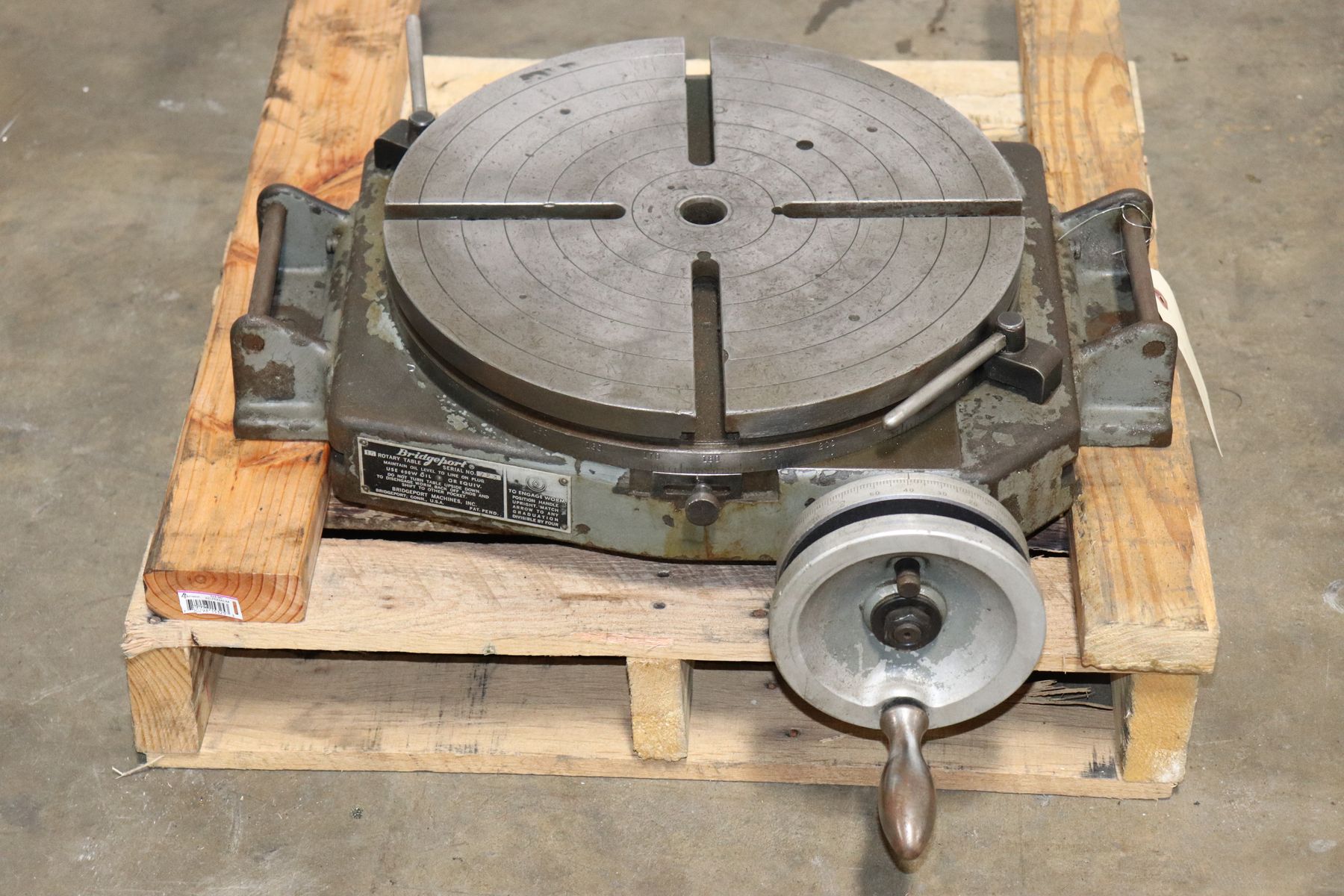
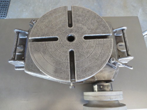
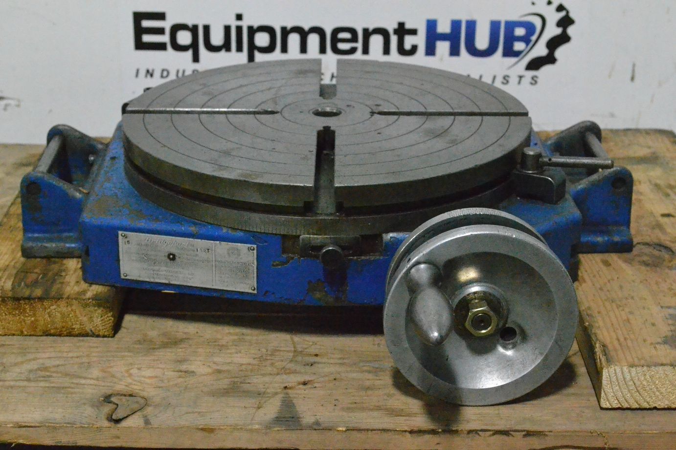
Bridgeport rotary tables are ruggedenough for the heaviest type ofproduction work, yet sensitive enoughfor precision tool work. Two models, 12and 15" diameters, will accommodatemost jobs found in the average shop.Table is of minimum height - 4 1 4" - topermit maximum tool clearance.Accuracy is within 30 seconds of arcthrough a complete rotation of thetable which is graduated each degree.An adjustable dial on the hand wheelreads directly to each minute. AVernier plate permits direct readingto within 5 seconds.rotary tablesSPECIFICATIONS in inchesRT-12RT-15A 4 1 4 4 1 4B 14 17C 1% 1%t---JI AC- li-0 4 1 4 5%E % %MJ - ~ KF 7 9 /16 9 1 /16G 13 1 lfl6 14lfl6H 4% 4%57"a 5%J 12 15K 117"a 147"al 1 1 4 114M 8% 10GEAR RATIO 90:1HGr- -,l r-- -nIVN 1 1Right AngleMountingBracketHorizontal MountingRight Angle Mounting Bracketwith Dividing Attachment with Dividing Attachment and Dividing AttachmentTail Stock with Centers38
For hydraulic duplicating or wherever one or moreparts must be made from a single master, Bridgeporthas developed a 12" tandem rotary table. Thesetables can be flush mounted in tandem and driven bya hydraulic motor. Number of units is limited onlyby the capacity of the motor used. A commonshaft drives all tables, with the same accuracyobtained as with the regular model - 30 seconds ofarc through a complete rotation.These tandem tables are ideal for cam work or onoddly shaped pieces and will accommodate any partwhich can be rotated without interference.tandem rotary tablesSPECIFICATIONS in inchesMODELTRT-12r----B-----IAB12V8C 1%D2V2E %F 4%JG 12H 5J 111/ 8Kf-----B-------I------------- K --------------,~LM 6N 1GEAR RATIO 90:139
quick change toolsBridgeport, known the world over for accuracy andeconomy, introduces an improved system of quick changetools. One holder accommodates adapters for straightand taper shank drills, boring tools, reamers, end mills,flycutters, chucks and straight shank cutting tools.Bridgeport quick change tools are manufacturedto the same high standards which distinguishBridgeport Millers. They are available in a range ofsizes to handle most of the jobs found in a productionshop. See your Bridgeport Dealer for prices andcomplete specifications.• One holder accommodates all tool adapters.• Repetitive accuracy of spindle assured.• Machine flexibility increased.• Down time for tool change eliminated.• Tools can be hand tightened, wrench locked.• Solid taper fit eliminates tool chatter and drift.• Quick Change Holder of alloy steel,heat treated and ground.40
HOLDERquick change toolsCAT. NO.QJ-H for all quick change adaptersKEY WRENCHCAT. NO.QJ-50 for quick change holderKEY INCLUDED WITH HOLDERSTRAIGHT SHANK ADAPTERSCAT. NO. SHANK DIAM. CAT. NO.QJ-2 Va" QJ-I0QJ-3 0/16" QJ-llQJ-4 IA" QJ-12QJ-6 %" QJ-13QJ-8 \12" QJ-14SHANK DIAM.o/a"lY16"%"10/16""l"a"BORING HEAD ADAPTERCAT. NO.QJ-21 for #1 Bridgeport Boring HeadQJ-22 for #2 Bridgeport Boring HeadJACOBS CHUCK ADAPTERSCAT. NO. SIZE CAT. NO. SIZEQJ-23 #0 Taper QJ-28 #4 TaperQJ-24 #1 Taper QJ-29 #5 TaperQJ.25 #2 Taper QJ-30 #6 TaperQJ-26 #2 Short Taper QJ-31 #33 TaperQJ·27 #3 TaperTAPER SHANK ADAPTERSCAT. NO.QJ-33QJ-34QJ-35QJ-36TAPER SHANK#1 Morse#2 Morse#7 B&S#5 B&SFLYCUTTER ADAPTERCAT. NO.QJ-37 for both #3 and #4 Bridgeport FlycuttersSHELL MILL ADAPTERSCAT. NO. SIZE ARBORQJ-38 %"QJ-39\1/"CUTTING TOOLS NOT INCLUDED
Iboring headsBoring heads increase the flexibility of BridgeportMillers to include all types of boring jobs within therange Of the unit. Heads have a graduated dialfor direct reading of adjustment in thousandths.NO.1 Head accommodates %" diameter boring toolsand is adjustable from zero reading to %".NO.2 Head accommodates %" diameter borings toolsand is adjustable from zero reading to W".Boring head shanksSpecial shanks as illustrated are available forboth models of Bridgeport Boring Heads.All heads are supplied with necessary wrenches,mounting block and metal container. Boring headshanks are available in a variety of tapers.SPECIFICATIONS in inchesNo.1No.2A 2 1 4 3%B 114 1%C % H"16D Adjustment % V2E Size Tool Taken % %AD,oor/"\""" ,_,, ,,,,I \ ,1...~ "". I"42
- - - - - - -----------------~...,-colletsfor Bridgeportattachments~--~~~~\Io...-__-===::::\:::::=~JI"R-B COLLETFor use with Model J and R heads, NO.3 Right-AngleAttachment. Holds tools from 1/8 through %"B-3 COLLETFor use with Model C and T heads. Holds tools from1/16 through 1/2".l" 10° Fill IY32~~~~~~(===]---r.3~ d~10·32 THO.N-2 COLLETFor use with Bridgeport No.2 Right-AngleAttachment. Holds tools from 1/16 through l/.t".NO. 7 B&S COLLETFor use with Model M and T heads. Holds toolsfrom 1/16 through V2".%·16 THO.B-2 COLLETFor use with No.1 Right·Angle Attachment. Holdstools from 1/16 through V2".NO, 2 MORSE COLLETFor use with Model M and T heads. Holds tools fromVI6 through 1/ 2".1.250"ll6·20 THO.NO. 16-S COLLETFor Model R milling head (old style). Holds tools fromV8 through %"43
shell mill arborsfor Shell End Mills..These arbors are for usewith the Model J head andare furnished withWrench for No.1 No.1 takes Shell Mills from 11,4 to 1 1 / 2 Bridgeport"s R-8 taper.Wrench for No.2 No.2 takes Shell Mills from 1% to 2Wrench for No.3 No.3 takes Shell Mills from 2114 to 2%threaded arborsfor Shell Mills or Milling Cutters with threaded holesThese arbors are supplied in two sizes, either left orright hand thread for angle milling cutters withthreaded holes. Smaller arbor ta kes 114" cutters;larger arbor ta kes 1%" cutters.47
stub arborsFor use with the Model J head, these arbors are for usein applications where the use of slitting saws, side millsor alternate tooth milling cutters are required. On gangjobs, it is suggested that the Bridgeport designed ArborSupport be used to obtain maximum rigidity. Arbors areheat treated and ground. Spacers are ground paralleland square with the bore of the spacer. All arborsare provided with wrench flats on the shoulders tofacilitate mounting or removal of arbor nut.SPACERS for use with Bridgeport Stub Arbors.SPECIFICATIONS in inches1.0. lengththreaddirectionA B C DSA-82 V2 %SA-83 V2 %6SAR-8 Right 6 V2 1% 2%2SA-I02 % 1/2SAL-8 Left 6 1/2 1% 2%2SA·I03 % 14SAR·lO Right 60/16 % 1% 31132 SA-124 % 2SAL-IO Left 6 5 1i6 % 1%31132 SA-122 % %SA-123 % 5/16SAR-12 Right 6% % 2 1 /8 1%2SA-144 ~8 2SAL-12 Left 6% % 2 1 /8 1%2SA-142 % %SAR-14 Right 6~8 1"8 2 1 4 1%2 SA-143 % 5/16SAL-14 Left 6% % 21;4 1%2 SA-164 1 2SA-162 1 %SAR-16 Right T%6 1 2 1 /2 1 11 132SA-163 1 51i6SAL-16 Left 70/16 1 2V2 llV32SA-204 114 2SAR-20 Right 70/16 114 2% 1 1 %2 SA-202 1 1 4 %SAL-20 Left 70/16 1 1 4 2% 1 15 /32 SA-203 1 1 4 %48t.949IG"---------- --R-8 TAPER16"-51"B
arbors____________ A_12501-:--c-SPACERS for use with Bridgeport Arbors.SPECIFICATIONS in inchesI.D.lengthth readdirectionA B C DSAR-12-P Right 14 29 /32 % 9%2 1/2SAL-12-P Left 14 2 %2 % 9%2 1/2SAR-14-P Right 15 1 /32 1"8 9 13 / 32 lV16SAL-14-P Left 15 1 /32 1"8 9 13 / 32 1V16SAR-16-P Right 15%2 1 9 17 / 32 1V16SAL-16-P Left 15%2 1 9 1 1"32 11/ 16SAR-20-P Right 15 1 %2 114 9 2 V32 1V16SAL-20-P Left 15 1 %2 114 9 2 V32 1V16SA-124SA-122SA-123SA-144SA-142SA-143SA-164SA-162SA-163SA-204SA-202SA-203% 2% %% o/i61"8 21"8 %1"8 0/161 21 %1 5/ 161l,4 2114 %114 %fly cuttersThese cutters are designed for Bridgeport"s Model Jhead. Used with a NO.3 Shell Mill Holders theywill accommodate 0/16" square tool bits, singly or inpairs. Tool bits may be set at 5 degrees positiverake, 5 degrees negative rake or at zero rake. Theyare inserted in diametrically opposed broachedholes. Bodies are made of mild steel.SPECIFICATIONS in inchesFC 3FC 400/1.CU,tQJe0 sA 1% 1%B 3 4C 2% 3%pO0 SON49
hold down bolt and nut setThis handy set is in great demand by machinistswho operate Bridgeports. Set No. TNS-500 iscompact and comes in a sturdy metalcontainer with notched holes to allow mounting on ornear the machine.SPECIFICATIONS in inchesamount part thread lengthTN-l 4 STUD 1/2 - 13 3TN-2 4 STUD 1/2 - 13 4TN-3 4 STUD 1/2 - 13 5TN-4 4 STUD 1/2 - 13 6TN-5 4 STUD 1/2 - 13 7TN-6 4 STUD Y2 - 13 8TN-? 4 FLANGE NUT 1/2 - 13TN-8 4 NUT COUPLERS Y2 - 13TN-9 4 "T" SLOT NUT 1/2 - 13 11"16TN-lO 1 HOLDERTN-l2 4 STRAP CLAMPsize% x 1%6~lo/W~50
Rotary Tables└ Workholding Supplies└ Workholding & Toolholding└ CNC, Metalworking & Manufacturing└ Business & IndustrialAll CategoriesAntiquesArtBabyBooks & MagazinesBusiness & IndustrialCameras & PhotoCell Phones & AccessoriesClothing, Shoes & AccessoriesCoins & Paper MoneyCollectiblesComputers/Tablets & NetworkingConsumer ElectronicsCraftsDolls & BearsMovies & TVEntertainment MemorabiliaGift Cards & CouponsHealth & BeautyHome & GardenJewelry & WatchesMusicMusical Instruments & GearPet SuppliesPottery & GlassReal EstateSpecialty ServicesSporting GoodsSports Mem, Cards & Fan ShopStampsTickets & ExperiencesToys & HobbiesTravelVideo Games & ConsolesEverything Else
Prerequisites: authorization on either [manual Bridgeport mill OR Clausing lathe] AND ShopBot CNC router. In other words you must be authorized on one manual cold metals manual machining center (lathe or mill) AND you must have been authorized on the operation of the ShopBot CNC router. You must be comfortable operating both of those prequalifying tools without supervision. The member to be authorized must be able to generate a toolpath in Fusion 360 with a simulated machining time of 2 minutes or less and must be able to provide a piece of stock and a single ended endmill 3/8" or smaller with a 3/8" shank that is appropriate for the toolpath.
Almost everything. The table and quill move as expected using the Heidenhain controller and joystick, including the handwheel. We can create and run simple programs using the Heidenhain conversational programming mode. We have switched the machine over to ISO G-code, and have been able to run programs with this. We have changed the communication parameters to FE mode, which permits transferring programs to/from the machine"s memory, as well as drip feeding programs directly.
The machine was wired at the factory for 460 volt 3 phase and we use 230 volt 3 phase in our shop. Ed and Dean rewired the motor and controller box, in a temporary fashion, to use 230v. It had been using a 460 to 230 volt transformer. Ryan removed this 6/26/2015 and changed all three transformers to use 230V, and re-enabled the accessory outlets at the rear of the machine. He also moved the Heidenhain power source back to the Bridgeport control. PS:One has voltage approaching 250V, so in some cases the voltages at transformer taps are a bit high. However the Heidenhain power, and the external 120V outlets, appear pretty much spot on.
Y axis ball screw cover is bent and not sliding properly. It should be removed and replaced (or bent straight). Removal is difficult because it is bent. This could require removing the table, which is heavy.
The homing sequence could not complete due to a bad index signal from the y axis rotary encoder. By adjusting the alignment of the encoder to the motor, the signal appeared. This adjustment may need attention in the future.
Because the Interact Series 1 uses tool holders, not collets, you are supposed to mount each tool in its own holder (which hopefully fixes its length relative to the spindle). You mount your longest tool, touch off the workpiece, call that point Z=0, and designate its tool offset as 0. Then you mount each tool in turn, touch off the workpiece, and store the different Z value (which will be negative) as the tool offset of each other tool. You can define tool offsets in G-code, but Aspire doesn"t seem to have that concept. Ryan changed machine parameter 225 to define 25 slots in a central tool table. This is a special Program 0, where you manually key in all your tool offsets and radius values (but that generally isn"t used for CAM-generated G-code.) So if T=1 is my zero tool, a cut to Z-0.5 will move the spindle to Z-0.5 and cut a half inch into the workpiece. But if I change to tool T=2 which has a L-1.0 offset, a cut in G-code to Z-0.5 will move the spindle to T-1.5, but since the tool is 1 inch shorter, it will cut a half inch into the workpiece. But it is critical now to check the global tool table before running a job!


 8613371530291