
bridgeport rotary table parts free sample
Years ago, before I learned CNC, I owned a Phase II 8″ horizontal/vertical rotary table that I purchased from Kap Pullen’s Getmachinetools.com store. He has them at a good price, BTW, and he’s a darned nice fellow to deal with as well as being a frequent HSM contributor. Anyway, its a nice little table, but I hadn’t done a whole lot with it for quite a while after purchasing it. As is so often the case, one day, a project landed on my doorstep and I was glad to have it.
Before I could get started, however, I had to make some accessories for it. Basically, I needed some T-Nuts to fit the table, as well as a little fixture that makes it easy to hold a plate up off the table through a hole in the center so you can machine it. The latter, what I call a “plate machining fixture”, was inspired by something similar I saw the Widgitmaster of CNCZone fame using to make Dremel clamps for his mini-router:
The Plate Maching Fixture and 3 Homemade T-Nuts. T-Nuts are easy to make: square a block to the proper dimensions, mill the side reliefs, drill, and tap. These are much smaller than the mill’s Bridgeport standard T-slots, so I made them myself and I’m using 1/4-20 bolts with them. They’re made of mild steel.
I turned the round spigot using the 4-jaw on the lathe. I’m making the fixture out of MIC-6 aluminum plate, which is pre-ground very flat on the sides. This is a 5 inch by 3 inch piece. I’ve clamped it to the rotab using my T-nuts and the regular mill clamps and step blocks. It is sitting on parallels to make sure I don’t cut into the table. You can also see how I’ve clamped the rotary table to the mill table using a big cast iron V-block I have. You can never have to many blocks with precision faces hanging around!
Having a 4-jaw chuck on your rotary table is mighty handy! Because it’s a 4-jaw, you can dial in the workpiece by adjusting the jaws until it is perfectly concentric with the table’s axis of rotation. The best way is to make an adapter plate that attaches to the back of the chuck in the same way that your lathe does so you can exchange lathe tooling with the rotab. Here is an example:
For the example, the chuck is threaded onto the adaptor plate, and then the holes in the adapter plate’s flange are used to bolt down to T-nuts on the table.
In my case, I bought a 4-jaw from Shars brand new, and simply drilled some through-holes in the chuck to mount to the table directly without an adapter plate:
First, you want to make sure your part is properly centered on the table. To do that, I clamp the table down on the mill table (no special place is needed), put my Indicol indicator holder on the mill spindle, and find some round feature on the part to indicate on. For example, on the plate milling fixture above, indicate on the round boss, or on the center hole. Spin the table and bump the part in until spinning the table doesn’t move the indicator.
Second, locate the center of rotation directly under the mill spindle. You can simply use the X and Y table handwheels to do this. Use that Indicol to indicate off of a circular feature you want centered under the spindle. Turn the indicol around on the spindle and adjust the handwheels until the indicator stays put relative to the spindle position. A Blake Coaxial indicator will make this last even simpler.
When you’re rounding partially by cranking a part around on the rotary table, it’s really easy to go a little too far and screw things up. The answer is to drill the end points to make the exact stopping point on the rotab a lot less sensitive:
Centering with a Blake indicator is really fast, but what if you don’t have a Blake, or worse, what if your mill is too small to accomodate one? Here is a nice solution I found on a German site. This fellow has made an ER collect fixture for his rotary table, and has taken care that when installed on the table, the axis of the collet is aligned with the table’s axis. He can then place a dowel or other straight pin in the collet and line up until it will go into a similarly sized collet on the spindle. Nice trick! It’s similar to how Widgitmaster showed me to align a drill chuck on a QCTP to the lathe centerline with a dowel pin held in the lathe chuck.

A recent model Knee Mill made by the Bridgeport company. This is the gold-standard small shop manual milling machine in the US. Most other mills of the same size are direct copies of the bridgeport design. This particular machine is a Series I, J-head with a mechanical variable speed drive. The machine has a power quill feed built into the head, in addition to the additional equipment listed below. This machine is capable of facing, surfacing, drilling and slotting in materials ranging from plastics to mild steel. Harder metals may be cut if special cutters and coolant are available. This machine is not equipped with CNC controls, consequently curved paths are limited to circular arcs. These can be cut on pieces that can be mounted on the 8" rotary table or approximated to a desired precision using the simple or smooth arc functions of the DRO.
The Bridgeport authorization is in two parts: once you have the prerequisite authorization, you need to complete the Canvas course; then, contact an authorizer to schedule the in-person portion of the authorization, where you will complete the auth project.

Rotary Tables└ Workholding Supplies└ Workholding & Toolholding└ CNC, Metalworking & Manufacturing└ Business & IndustrialAll CategoriesAntiquesArtBabyBooks & MagazinesBusiness & IndustrialCameras & PhotoCell Phones & AccessoriesClothing, Shoes & AccessoriesCoins & Paper MoneyCollectiblesComputers/Tablets & NetworkingConsumer ElectronicsCraftsDolls & BearsMovies & TVEntertainment MemorabiliaGift Cards & CouponsHealth & BeautyHome & GardenJewelry & WatchesMusicMusical Instruments & GearPet SuppliesPottery & GlassReal EstateSpecialty ServicesSporting GoodsSports Mem, Cards & Fan ShopStampsTickets & ExperiencesToys & HobbiesTravelVideo Games & ConsolesEverything Else

A rotary table is a precision work positioning device used in metalworking. It enables the operator to drill or cut work at exact intervals around a fixed (usually horizontal or vertical) axis. Some rotary tables allow the use of index plates for indexing operations, and some can also be fitted with dividing plates that enable regular work positioning at divisions for which indexing plates are not available. A rotary fixture used in this fashion is more appropriately called a dividing head (indexing head).
The table shown is a manually operated type. Powered tables under the control of CNC machines are now available, and provide a fourth axis to CNC milling machines. Rotary tables are made with a solid base, which has provision for clamping onto another table or fixture. The actual table is a precision-machined disc to which the work piece is clamped (T slots are generally provided for this purpose). This disc can rotate freely, for indexing, or under the control of a worm (handwheel), with the worm wheel portion being made part of the actual table. High precision tables are driven by backlash compensating duplex worms.
The ratio between worm and table is generally 40:1, 72:1 or 90:1 but may be any ratio that can be easily divided exactly into 360°. This is for ease of use when indexing plates are available. A graduated dial and, often, a vernier scale enable the operator to position the table, and thus the work affixed to it with great accuracy.
Rotary tables are most commonly mounted "flat", with the table rotating around a vertical axis, in the same plane as the cutter of a vertical milling machine. An alternate setup is to mount the rotary table on its end (or mount it "flat" on a 90° angle plate), so that it rotates about a horizontal axis. In this configuration a tailstock can also be used, thus holding the workpiece "between centers."
With the table mounted on a secondary table, the workpiece is accurately centered on the rotary table"s axis, which in turn is centered on the cutting tool"s axis. All three axes are thus coaxial. From this point, the secondary table can be offset in either the X or Y direction to set the cutter the desired distance from the workpiece"s center. This allows concentric machining operations on the workpiece. Placing the workpiece eccentrically a set distance from the center permits more complex curves to be cut. As with other setups on a vertical mill, the milling operation can be either drilling a series of concentric, and possibly equidistant holes, or face or end milling either circular or semicircular shapes and contours.
with the addition of a compound table on top of the rotary table, the user can move the center of rotation to anywhere on the part being cut. This enables an arc to be cut at any place on the part.
Additionally, if converted to stepper motor operation, with a CNC milling machine and a tailstock, a rotary table allows many parts to be made on a mill that otherwise would require a lathe.
Rotary tables have many applications, including being used in the manufacture and inspection process of important elements in aerospace, automation and scientific industries. The use of rotary tables stretches as far as the film and animation industry, being used to obtain accuracy and precision in filming and photography.

wide range and selection for our customers.*Power Feeds *Motion Control *Drives*Servo*Readout Systems*Tooling*Parts to repair all these systems as well.
We offer Bridgeport Milling Machines that have been serviced by our TAS IRON LTD facility in Berea, Ohio. Some of the best pricing around. Your need to have your Bridgeport serviced and brought back to a good service. Send it to us, we will send it back ready to work. We have serveral in stock machines available as well as we take orders, if you want one unit or ten units, we will build them for you.
We offer crating service and free loading and packaging. Don"t take a chance on buying a used machine tool until you give us a chance. If you need glass scales installed, Table feed drives, what ever it may be, we do it here. So when your mill breaks down, send it in to get repaired, a lot of times its more cost effective.
modelBR2J1 "/2 h.p.turret millerBridgeport"s Model BR2J is aheavy-medium duty machineequipped with a model 2J variablespeed milling, drilling and boringhead as standard equipment.However, with the use of acombination of Bridgeport headattachments, the capacity ofthe machine includes right anglemilling, drilling and boringas well as vertical. Profiling, slotting,cherrying, flycutting and jig boringcan also be accomplished.Angles in all planes are set throughworm gear controls. Ram typeconstruction permits movement ofhead over the ta ble withoutrechecking the squareness of thespindle.In and out movement of the ram,through rack and pinion, iseffortless. The rear end of the ramhas a regular swivel adapter formounting additional heads, givingangular settings in both verticaland horizontal planes.FEATURES• Expanding dovetail locks ram and turret into oneunit to prevent vibration.• Column, knee and table are constructed with extra wide ways andtaper gibs for maximum rigidity.• All operation controls are at the operator"s fingertips;graduated dials are extra large for easy reading.• Anti-friction bearings are used throughout the machine.• Worm and gear controls are used for angular settings of head.• Wick feed lubrication distributes oil to all spindle bearings andmoving parts by means of a flush system.6
Ao MIN.12MAX./~oor 45"DB}-------- C -------1SPECIFICATIONS in inches MODEL 9BR2J MODEL 12BR2JTABLE LENGTHS 32 36 42 48 32 36 42 48LONGITUDINAL TRAVEL - manual 20 24 30 36 20 24 30 36LONGITUDINAL TRAVEL - power feed 16 1 /2 20 1 /2 26 1 /2 - 16 1 /2 20 1 /2 26 1 /2 -CROSS TRAVEL-9 9 9 9 12 12 12 12VERTICAL TRAVEL OF KNEE 16 16 16 16 16 16 16 16A OVERALL HEIGHT-82 3 / 16 823116 82 3 / 16 823116 82 3 /16 82 3 / 16 82 3 / 16 82 3 / 16B OVERALL DEPTH 58% 58% 58% 58% 63 63 63 63C OVERALL WIDTH 65 1 /2 69 1 /2 75 1 /2 811/2 65Y2 69 1 /2 75 1 /2 811/2DEFGMIN. DISTANCE 0 0 0 0 0 0 0 0MAX. DISTANCE 18Y2 18Y2 18 1 /2 18 1 /2 18 1 /2 18 1 /2 18 1 /2 18 12MIN. DISTANCE 0 0 0 0 0 0 0 0MAX. DISTANCE 12 12 12 12 12 12 12 12MIN. DISTANCE 6% 6% 6% 6% 6% 6% 6% 6%MAX. DISTANCE 18% 18% 18% 18% 18% 18% 18% 18%MIN. DISTANCE 8%. 8% 8% 8% 8% 8% 8% 8%MAX. DISTANCE 20% 20% 20% 20% 20% 20% 20% 20%oMODEL "2J" VARIABLE SPEED HEAD SPINDLE - R 8 taperSPINDLE SPEEDS - infinitely variable from 60 to 4200 R.P.M. COLLET CAPACITY - %POWER FEED per spindle revolution - .0015 .003 .006 QUILL TRAVEL - 57
modelBRJ1 h.p.turret millerBridgeport"s Model BRJ is aheavy-medium duty machineequipped with a model "J" milling,drilling and boring head asstandard equipment.However, with the use of acombination of Bridgeport headattachments, the capacity ofthe machine includes right anglemilling, drilling and boringas well as vertical. Profiling, slotting,cherrying, flycutting and jig boringcan also be accomplished.Angles in all planes are set throughworm gear controls. Ram typeconstruction permits movement ofhead over the ta ble withoutrechecking the squareness of thespindle.In and out movement of the ram,through rack and pinion, iseffortless. The rear end of the ramhas a regular swivel adapter formounting additional heads, givingangular settings in both verticaland horizontal planes.FEATURES• Expanding dovetail locks ram and turret into oneunit to prevent vibration.• Column, knee and table are constructed with extra wide ways andtaper gibs for maximum rigidity.• All operation controls are at the operator"s fingertips;graduated dials are extra large for easy reading.• Anti·friction bearings are used throughout the machine.• Worm and gear controls are used for angular settings of head.• Wick feed lubrication distributes oil to all spindle bearings andmoving parts by means of a flush system.8
Ao MIN.12MAX./~7, ,~~ E: G---+---ioB C -----------1SPECIFICATIONS in inches MODEL 9BRJ MODEL 12BRJTABLE LENGTHS 32 36 42 48 32 36 42 48LONGITUDINAL TRAVEL - manual 20 24 30 36 20 24 30 36LONGITUDINAL TRAVEL - power feed 16 1 /2 20 1 /2 26 1 /2 16 1 /2 20 1 /2 26 1 /2 -_.CROSS TRAVEL 9 9 9 9 12 12 12 12VERTICAL TRAVEL OF KNEE 16 16 16 16 16 16 16 16A OVERALL HEIGHT 71"7/ 16 777/16 777/16 777/16 777/16 777/16 777/16 777/16B OVERALL DEPTH 58% 58% 58% 58% 63 63 63 63C OVERALL WIDTH 65 1 /2 69 1 /2 75112 811/2 65 1 /2 69 1 /2 75 1 /2 8Il!2DEFGMIN. DISTANCE 0 0 0 O. 0 0 0 0MAX. DISTANCE 18 1 /2 18 1 /2 18112 18112 18 1 /2 18 1 /2 18112 18 1 /2MIN. DISTANCE 0 0 0 0 0 0 0 0MAX. DISTANCE 12 12 12 12 12 12 12 12MIN. DISTANCE 6% 6% 6% 6% 6% 6% 6% 6%MAX. DISTANCE 18% 18% 18% 18% 18% 18% 18% 18%MIN. DISTANCE 8% 8% 8% 8% 8% 8% 8% 8%MAX. DISTANCE 20% 20% 20% 20% 20% 20% 20% 20%MODEL "J" HEAD SPINDLE - R-8 taperSPEEDS, R.P.M. - 80 135 210 325 660 1115 1750 2720 COLLET CAPACITY - %POWER FEED per spindle revolution - .0015 .003 .006 QUILL TRAVEL - 59
modelBRM"/2 h.p.turret millerBridgeport"s Model BRM turret milleris a medium-light duty machinewhich has a thousand and oneapplications in machine shops, jobshops, experimental labs,maintenance and repair shops, andeven home workshops.This machine is a Basic Bridgeport"chassis" equipped with a Model"M" Master milling head, which hasall the accuracy and advantagesof the larger "J" head except that itis rated at 1/2 H.P., and does nothave power down feed to quill.In addition to vertical and horizontalmilling, this machine can handle alltypes of machining operationsincluding drilling, boring, jig boring,cherrying, shaping, flycutting,profiling and slotting.FEATURES• Column, knee and table are constructed with extra wide ways andtaper gibs for maximum rigidity.• Anti-friction bearings are used throughout.• Convenient location of all controls makes for less operatorfatigue, faster production.• Ram moves in and out easily through rack and pinion.• Worm and gear controls are used for angular settings of head.• Table, knee and saddle locks located in front of machinefor convenience.10
----~---j/~/45°Ao MIN.12 MAX.o~--------B---------.{t--------C----------JSPECIFICATIONS in inches MODEL 9BRM MODEL 12BRMTABLE LENGTHS 32 36 42 48 32 36 42 48LONGITUDINAL TRAVEL - manual 20 24 30 36 20 24 30 36LONGITUDINAL TRAVEL - power feed 16Y2 20Y2 26 1 /2 - 16Y2 20Y2 26 1 /2 -CROSS TRAVEL 9 9 9 9 12 12 12 12-_. --VERTICAL TRAVEL OF KNEE 16 16 16 16 16 16 16 16A OVERALL HEIGHT 75 75 75 75 75 75 75 75B OVERALL DEPTH 58% 58% 58% 58% 63 63 63 63C OVERALL WI DTH 65 1 /2 69 1 /2 75V2 8l1/2 65 1 /2 69 1 /2 75 1 /2 8l1/2-0MIN. DISTANCE V2 V2 1/2 1/2 1/2 1/2 Y2 1/2MAX. DISTANCE 20 1 4 20 1 4 20 1 / 4 20 1 4 20 1 4 20 1 4 20 1 ,4 20 1 ,4- -MIN. DISTANCE 0 0 0 0 0 0 0E0._MAX. DISTANCE 12 12 12 12 12 12 12 12-MIN. DISTANCE 7 1 /2 7V2 7V2 7V2 7V2 7 1 /2 7V2 7 1 /2FGMAX. DISTANCE 19 19 19 19 19 19 19 19--MIN. DISTANCE 8 8 8 8 8 8 8 8MAX. DISTANCE 20 20 20 20 20 20 20 20MODEL "M" HEAD SPINDLE - No.2 Morse Taper;7 B&S Taper; or B-3 TaperSPEEDS, 1200 R.P.M. MOTOR 275 425 700 1050 2100 4250 COLLET CAPACITY - VB - 112SPEEDS, 3600 R.P.M. MOTOR 950 1350 2200 3250 6500 12000 QUILL TRAVEL - 3V211
Chrome Plated Ways -(Optional Feature)To maintain as far as possible the inherent accuracyand sensitivity of Bridgeport Millers, theexclusive feature of chrome plated ways is offered tousers of our machines.For a modest cost, Bridgeport can supply machineswhose ways are chrome plated at the points ofmaximum wear:• Back of Knee• Column Knee Gib• Top of Knee• Top of Saddle• Saddle Table GibChrome plate on these parts places a hard wearresistant surface on the paths of vertical, longitudinaland cross travel.A .002 deposit is made to assure ample wear life,an ideal lubricating surface and the lowest possibleco-efficient of friction. Hardness exceeds RockwellC-70. The chrome plate becomes an integral partof the base casting and does not set up anystresses or strains.To provide our customers, large or small with the mostversatile and flexible turret millers, Bridgeport hasdesigned and developed six working heads.These heads are supplied in a range of powers andcapabilities to handle most of the machining operationsrequired in any machine shop.All head models can be mounted on the front end of theram where they can be moved or swiveled to cover allplanes and angles in the spectrum.Models M, T and E can be mounted on the rearend of the ram and can beswung around to operate over the table.FEATURES COMMON TO ALL BRIDGEPORT HEADS• Self-contained, can be mounted on other machines.• Spindles are chrome nickel alloy, heat treatedand ground.• Spindle housings of high grade semi-steel castings.• Spindle bearings precision preloaded, accurately spacedfor maximum radial and thrust capacity.• Oil cup provides lubrication to all spindle bearings.• Dynamically balanced V belt pulleys proportioned forlong belt life, positive traction.• Simple adjustment of belt tension throughpivotally mounted motors.12
The Model "J" is the workhorse of Bridgeport"s line ofheads. It has a combination of power and accuracyunmatched in any other make.It is equipped with power down-feed and up-feed.Angular positioning is obtained through anintegral worm and gear.The Model "J" is designed for continuous duty inthe vertical position, but can be modified forcontinuous horizontal operation.Extreme sensitivity is provided by acounterbalanced quill and spindle.modelJ1 h.p. milling, drillingand boring head-----8-------jI------C--------lFEATURES• Separate manual feed provides for rapid movementof quill, lever operated; slow movement by meansof a hand wheel.• Positive quill lock.• Micrometer depth stop graduated in thousandths.• Equipped with reversible switch for rightor left hand operation.• Spindle drive is back geared for maximum use ofpower.• Positive two way power feed tripping mechanism.SPECIFICATIONS in inchesA OVERALL HEIGHT - 27 1 4AB OVERALL DEPTH 19C OVERALL WIDTH 18POWER FEED per spindle rev. - .0015 .003 .006l7"12ISPINDLE -R-8 taperCOLLET CAPACITY - %QUILL TRAVEL - 5SPEEDS, 1800 R.P.M. MOTOR80 135 210 325 660 1115 1750 2720SPEEDS, 3600 R.P.M. MOTOR160 270 440 660 1320 2200 3600 544015
modelT"/2 h.p. cherrying headModel "T" cherrying head was designed and engineeredto meet the need for an economical method ofeliminating the time consuming hand work in die sinking.Small die work can be done effectively with the "TO,head mounted on a Bridgeport Turret Miller.This head has an oscillating quill which can move anordinary die sinking cutter through a circular path eitherconvex or concave to perform both rough and finishedcherrying operations. Radius is adjustable from 0 to 1%".A quill lock is supplied to lock the quill in a fixedposition when conventional milling work is called for.This head ca n be operated at right angles to bothcross and longitudinal travel of the table.SPECIFICATIONS in inchesA OVERALL HEIGHT - 27%AB OVERALL DEPTH20C OVERALL WIDTH 17%SPINDLENO.2 Morse Taper; 7 B&S Taper; or B·3 TaperCOLLET CAPACITY -V2SPEEDS, R.P.M.275 425 700 1050 2100 425016
Shaping Tool SetFor use with Model E head. Consists ofseven shaped tools and threestandard tool bit holders.modelE"/3 h.p. verticalshaping head-"1":. .The model "E" vertical shaping head can perform alimitless variety of shapes using only standard tool bitholders and tools.It ca n be placed in a plane at right angles to thetable, or any vertical or compound angle desired.Strokes from zero to 4" can be dialed inincrements of 1/8 ".This head can be mounted on the rear end of theram of Bridgeport"s BRJ or BRM machine, to be readywhen a shaping job comes up.SPECIFICATIONS in inchesA OVERALL HEIGHT - 20 1 0/16B OVERALL DEPTH 177116C OVERALL WI DTHSTROKE - 4STROKES PER MINUTE70 100 145 205 295 4202"1aMIN.6"1aMAX.j20
The world"s NO.1 Miller didn"t get its reputation by beingthrown together. It takes time to build a Bridgeport right,and we don"t build them any other way. Why?Because every part must be accurate to Bridgeport"sstandard. Every part must be inspected and many arehand fitted. Without this special care the Bridgeportwould be just another miller. A Bridgeport is worth itswait in time, money and performance.
Each of the four attachments shown is an integralunit in itself. Cutter spindle and driving spindle aremounted in their own anti-friction bearings.Mounting on proper head is quick and simple.The attachments slip easily on the quill of the head.Driving spindle or shaft is tightened first; thenthe right-angle attachment clamping screw is tightenedto hold the unit firmly to the quill.No.1right-angle attachmentsfor model M headThese 90° attachments are designed to increase evenfurther the capacity and flexibility of theBridgeport equipped with a Model HM" milling head.They are used for horizontal milling, drilling, boringand reaming on light or awkward jobs.No.1 and 2 attachments are ideal for milling outpockets and cavities and for rough and finishmachining of small or unusual pieces.No.2SPECIFICATIONS in inchesA---;No.1 No.2 -2.563A 3% 3%B 5Y16 6Y2C 1%2 2%2BD 3% 110/16E Ira 30/16COLLET NO. B-2 N-2COLLET CAPACITY 1/16 - 1/2 Y16- 1 4ESPEED REDUCTION 2 to 1 2 to 1M IN. WORKING SPACE 4 2%No.1No.224
To supplement the right-angle attachments listedelsewhere, Bridgeport has developed theQuillmaster attachment for use with the models M,T and J heads.The spindle housing swivels on a plane which is at a45 0 angle to the Quillmaster"s axis. This allows the"business end" of the Quillmaster to operate in anycompound angle from vertical to horizontal.Any corner with a small radius can be finish milled orcherried to a degree of sharpness not possible bya ny other method.For tool and die work the Quillmaster is a must.Moreover, its high speed allows the use ofsmall end mills.1/8" spring collet and 0/16" solid end mill holderavailable with the Quillmaster in addition to the 0/16"spring collet furnished.Type JAfor modelJ headQuillmaster attachmentfor models M, T and J headsType MAfor modelsM and T headsSPECIFICATIONS in inchesMAJAA 20/16 3% DB 9 9C 10/16 10/160 414 414BCOLLET CAPACITY - 3/1626
Bridgeport"s QRA attachment is a further expansionof the advantages of the Quillmaster. By providing aright-angle attachment for the Quillmaster, we havegiven the tool and die ma ker the last word inconvenience and flexibility.The QRA itself can operate in a confined space or holeonly 2 inches in diameter, and can operate effectivelywithin 1/2 inch of the wall of the workpiece. Itoperates with equal ease on the inside or outside ofirregularly shaped pieces or castings and is moreaccurate and sensitive than a dentist"s drill.The QRA attachment is a self contained unit,containing permanently lubricated bearingsand gear housing.QRA attachmentfor typesMA andJAQuillmasterSPECIFICATIONS in inchesA 1C 1%D 1COLLET CAPACITY - 0/16MINIMUM WORKING SPACE - 2Typical applications for the Quillmaster and the QRA attachment:27
lImeasuringattachmentThe Bridgeport measuring attachment is designedto provide the utmost accuracy in the coordinatelocation of holes. Its precision has been proven morethan satisfactory in a multiplicity of toolroom jobsall over the world.Accuracy is controlled entirely by end measures,inside micrometers and dial indicators.In use, the table and saddle are located separatelyby combinations of end measure for even inches, aninside micrometer for fractions of an inch, and a dialindicator reading for ten thousandths of an inch.When extremely precise operations are beingperformed, the conventional table and saddle locksare not used. Clamping is done by special reedtype clamps which do not transfer stresses tothese members.29
,,""11""""""--==-=====-=====--- --------OIMrNSIONS REAO 11"1 f(NTI-iSopticalmeasuringsystemThe Bridgeport Optical System is a quick, accurate,dependable method of locating machine worktables without danger of wear and consequentinaccuracy.In the Bridgeport system, no mechanical contact isinvolved, and there are no parts to be handled.Mathematical calculations are not required becausewith the Bridgeport Optical Measuring Systemfigures are read on the scale exactly as they appearon the working drawing. The operator is required onlyto read a single line which appears on an accuratescale calibrated every .010". Vernier estimatesare eliminated.Installation is quick and easy with the majority ofmounting holes already in place on standardBridgeport millers.Operation is trouble-free. Both the scale and theunit are sealed against foreign matter, andthe scales are permanently covered with glass.Distortion-free clamps keep sliding membersin position.FEATURES• Easily accessible setting knob.• Jump-proof table clamp.• Automatic light switch.• Catch fork system of direct digit reading.• Set up adjustment for even inches.• Sensitive parts sealed and protected.• Neoprene chip guard provided.SPECIFICATIONS in inchesLONGITUDINAL TRAVEL - 20CROSS TRAVEL - 9 or 12MAGNIFICATION - 17xREADING ACCURACY - .0001, directLATERAL ADJUSTMENT - 130
The coolant system for Bridgeportmachines is enclosed within thecolumn of the machine, using the baseas an oil or coolant reservoir. Coolantis supplied to the work piece or tablethrough a flexible hose and nozzle,and floods the working area through aflushing system. Bridgeport"s coolantsystem can be installed on newmachines or on those already in usevery easily through a door in thecolumn of the machine. In the lattercase it is supplied as a completepackage ready for field mounting.coolant systemsSpraymist Coolant Systems ...Spraymist directs a pressurizedmist of coolant where the toolcontacts the work and heat isgenerated. Heat is instantaneouslydissipated as the mist evaporates.Work finishes are improved, rejectsreduced ... no splash or spill onmachine, operator or floor.Spraymist makes possible operationof machines at higher speeds andfeeds for increased production.lubrication systemMetered Lubrication ...This lubricating system develops apressurized flow of oil that produces auniform film of lubricant on everybearing surface. The amount of oilsupplied to all bearings is preciselycontrolled to meet specificrequirements. This one-shotLubricating System can accuratelydeliver minute quantities of oil to onebearing ... while delivering muchgreater amounts to another. Theprecision operation of the systemassures proper lubrication with aminimum volume of oil.31
power feed unitThe power feed unit can easily beinstalled on any Bridgeport TurretMiller to give a selection of 12longitudinal table feeds from 9/16" to9Y16" per minute in geometricprogression. This unit is compact andself·contained, and can be mounted onexisting machines easily and quickly.The feed box is equipped with anoverload release which disengages thefeed when the tool is under unduestress. Once the load is released, thepower unit resumes operation. Thepower unit can be used on all tablesexcept the 48/1 model.---- B -------110SPECIFICATIONS in inchesA OVERALL HEIGHT - 13 1 /2B OVERALL DEPTH 11%C OVERALL WI DTH 19VsFEEDS per minute9/16 % 151i.6 111
iser blocksBridgeport millers can be provided withriser blocks to extend the height rangeof the machines by either 4 or 7 inchesto accommodate unusually large pieces,or to raise the overall working area ofthe machine. These blocks are easilymounted to the column of the machinewith fou r bolts .• •cross travel stopThis is an adjustable attachment whichis used to limit the amount of travel ofthe saddle to predetermined distances.It can be mounted on either side of theknee and set at selected settings toobtain a positive stop. It can bemounted easily and quickly by tappingtwo holes each in the saddle andthe knee.This surface shouldbe parallel withtravel of sadd IeTap two%-16 holesin kneeAttachment may be mountedon either side of knee33
10"plainsine tableTo set, for example, 111/2° anglewith 10" Sine Table (Plain or Comb.)find sine of 111/2°, which is .19937.Multiply .19937 by 10 in simply movingdecimal point one step to the right.Result: Dim. B = 1.9937.Use gageblocks or similar tool 1.9937and place under Sine Bar of tablegiving a correct setting of 111/2°.SPECIFICATIONS in inchesWORKING SURFACE-111/2 x 12SHIPPING WEIGHT-80 Ibs.Specify 10" Plain Sine Tablewhen ordering.35
The 5" Sine Table is constructed withthe same features as the 10".It is a very rugged and sturdy set-updevice, still light enough to be handledvery easily by one man.5" combination sine table5"plain sine tableSPECIFICATIONS in inchesCombinationPlainWORKING SURFACE Horiz. 5 x 7 63;"ax 7WORKING SURFACE Vert. 3Y2 x 7SHIPPING WEIGHT 351bs. 301bs.Specify 5" Combination or 5" Plain Sine Table whenordering.To set, for example, 9 045" angle with5" Sine Table (Plain or Comb.) findsine of 9 045" which is .16935. Multiply.16935 by 5. Result: Dim. B = .84675.Use gage-blocks or similar tool .84675and place under Sine Bar of tablegiving a correct setting of 9 0 45".36
Bridgeport rotary tables are ruggedenough for the heaviest type ofproduction work, yet sensitive enoughfor precision tool work. Two models, 12and 15" diameters, will accommodatemost jobs found in the average shop.Table is of minimum height - 4 1 4" - topermit maximum tool clearance.Accuracy is within 30 seconds of arcthrough a complete rotation of thetable which is graduated each degree.An adjustable dial on the hand wheelreads directly to each minute. AVernier plate permits direct readingto within 5 seconds.rotary tablesSPECIFICATIONS in inchesRT-12RT-15A 4 1 4 4 1 4B 14 17C 1% 1%t---JI AC- li-0 4 1 4 5%E % %MJ - ~ KF 7 9 /16 9 1 /16G 13 1 lfl6 14lfl6H 4% 4%57"a 5%J 12 15K 117"a 147"al 1 1 4 114M 8% 10GEAR RATIO 90:1HGr- -,l r-- -nIVN 1 1Right AngleMountingBracketHorizontal MountingRight Angle Mounting Bracketwith Dividing Attachment with Dividing Attachment and Dividing AttachmentTail Stock with Centers38
For hydraulic duplicating or wherever one or moreparts must be made from a single master, Bridgeporthas developed a 12" tandem rotary table. Thesetables can be flush mounted in tandem and driven bya hydraulic motor. Number of units is limited onlyby the capacity of the motor used. A commonshaft drives all tables, with the same accuracyobtained as with the regular model - 30 seconds ofarc through a complete rotation.These tandem tables are ideal for cam work or onoddly shaped pieces and will accommodate any partwhich can be rotated without interference.tandem rotary tablesSPECIFICATIONS in inchesMODELTRT-12r----B-----IAB12V8C 1%D2V2E %F 4%JG 12H 5J 111/ 8Kf-----B-------I------------- K --------------,~LM 6N 1GEAR RATIO 90:139
quick change toolsBridgeport, known the world over for accuracy andeconomy, introduces an improved system of quick changetools. One holder accommodates adapters for straightand taper shank drills, boring tools, reamers, end mills,flycutters, chucks and straight shank cutting tools.Bridgeport quick change tools are manufacturedto the same high standards which distinguishBridgeport Millers. They are available in a range ofsizes to handle most of the jobs found in a productionshop. See your Bridgeport Dealer for prices andcomplete specifications.• One holder accommodates all tool adapters.• Repetitive accuracy of spindle assured.• Machine flexibility increased.• Down time for tool change eliminated.• Tools can be hand tightened, wrench locked.• Solid taper fit eliminates tool chatter and drift.• Quick Change Holder of alloy steel,heat treated and ground.40
HOLDERquick change toolsCAT. NO.QJ-H for all quick change adaptersKEY WRENCHCAT. NO.QJ-50 for quick change holderKEY INCLUDED WITH HOLDERSTRAIGHT SHANK ADAPTERSCAT. NO. SHANK DIAM. CAT. NO.QJ-2 Va" QJ-I0QJ-3 0/16" QJ-llQJ-4 IA" QJ-12QJ-6 %" QJ-13QJ-8 \12" QJ-14SHANK DIAM.o/a"lY16"%"10/16""l"a"BORING HEAD ADAPTERCAT. NO.QJ-21 for #1 Bridgeport Boring HeadQJ-22 for #2 Bridgeport Boring HeadJACOBS CHUCK ADAPTERSCAT. NO. SIZE CAT. NO. SIZEQJ-23 #0 Taper QJ-28 #4 TaperQJ-24 #1 Taper QJ-29 #5 TaperQJ.25 #2 Taper QJ-30 #6 TaperQJ-26 #2 Short Taper QJ-31 #33 TaperQJ·27 #3 TaperTAPER SHANK ADAPTERSCAT. NO.QJ-33QJ-34QJ-35QJ-36TAPER SHANK#1 Morse#2 Morse#7 B&S#5 B&SFLYCUTTER ADAPTERCAT. NO.QJ-37 for both #3 and #4 Bridgeport FlycuttersSHELL MILL ADAPTERSCAT. NO. SIZE ARBORQJ-38 %"QJ-39\1/"CUTTING TOOLS NOT INCLUDED
Iboring headsBoring heads increase the flexibility of BridgeportMillers to include all types of boring jobs within therange Of the unit. Heads have a graduated dialfor direct reading of adjustment in thousandths.NO.1 Head accommodates %" diameter boring toolsand is adjustable from zero reading to %".NO.2 Head accommodates %" diameter borings toolsand is adjustable from zero reading to W".Boring head shanksSpecial shanks as illustrated are available forboth models of Bridgeport Boring Heads.All heads are supplied with necessary wrenches,mounting block and metal container. Boring headshanks are available in a variety of tapers.SPECIFICATIONS in inchesNo.1No.2A 2 1 4 3%B 114 1%C % H"16D Adjustment % V2E Size Tool Taken % %AD,oor/"\""" ,_,, ,,,,I \ ,1...~ "". I"42
- - - - - - -----------------~...,-colletsfor Bridgeportattachments~--~~~~\Io...-__-===::::\:::::=~JI"R-B COLLETFor use with Model J and R heads, NO.3 Right-AngleAttachment. Holds tools from 1/8 through %"B-3 COLLETFor use with Model C and T heads. Holds tools from1/16 through 1/2".l" 10° Fill IY32~~~~~~(===]---r.3~ d~10·32 THO.N-2 COLLETFor use with Bridgeport No.2 Right-AngleAttachment. Holds tools from 1/16 through l/.t".NO. 7 B&S COLLETFor use with Model M and T heads. Holds toolsfrom 1/16 through V2".%·16 THO.B-2 COLLETFor use with No.1 Right·Angle Attachment. Holdstools from 1/16 through V2".NO, 2 MORSE COLLETFor use with Model M and T heads. Holds tools fromVI6 through 1/ 2".1.250"ll6·20 THO.NO. 16-S COLLETFor Model R milling head (old style). Holds tools fromV8 through %"43
shell mill arborsfor Shell End Mills..These arbors are for usewith the Model J head andare furnished withWrench for No.1 No.1 takes Shell Mills from 11,4 to 1 1 / 2 Bridgeport"s R-8 taper.Wrench for No.2 No.2 takes Shell Mills from 1% to 2Wrench for No.3 No.3 takes Shell Mills from 2114 to 2%threaded arborsfor Shell Mills or Milling Cutters with threaded holesThese arbors are supplied in two sizes, either left orright hand thread for angle milling cutters withthreaded holes. Smaller arbor ta kes 114" cutters;larger arbor ta kes 1%" cutters.47
stub arborsFor use with the Model J head, these arbors are for usein applications where the use of slitting saws, side millsor alternate tooth milling cutters are required. On gangjobs, it is suggested that the Bridgeport designed ArborSupport be used to obtain maximum rigidity. Arbors areheat treated and ground. Spacers are ground paralleland square with the bore of the spacer. All arborsare provided with wrench flats on the shoulders tofacilitate mounting or removal of arbor nut.SPACERS for use with Bridgeport Stub Arbors.SPECIFICATIONS in inches1.0. lengththreaddirectionA B C DSA-82 V2 %SA-83 V2 %6SAR-8 Right 6 V2 1% 2%2SA-I02 % 1/2SAL-8 Left 6 1/2 1% 2%2SA·I03 % 14SAR·lO Right 60/16 % 1% 31132 SA-124 % 2SAL-IO Left 6 5 1i6 % 1%31132 SA-122 % %SA-123 % 5/16SAR-12 Right 6% % 2 1 /8 1%2SA-144 ~8 2SAL-12 Left 6% % 2 1 /8 1%2SA-142 % %SAR-14 Right 6~8 1"8 2 1 4 1%2 SA-143 % 5/16SAL-14 Left 6% % 21;4 1%2 SA-164 1 2SA-162 1 %SAR-16 Right T%6 1 2 1 /2 1 11 132SA-163 1 51i6SAL-16 Left 70/16 1 2V2 llV32SA-204 114 2SAR-20 Right 70/16 114 2% 1 1 %2 SA-202 1 1 4 %SAL-20 Left 70/16 1 1 4 2% 1 15 /32 SA-203 1 1 4 %48t.949IG"---------- --R-8 TAPER16"-51"B
arbors____________ A_12501-:--c-SPACERS for use with Bridgeport Arbors.SPECIFICATIONS in inchesI.D.lengthth readdirectionA B C DSAR-12-P Right 14 29 /32 % 9%2 1/2SAL-12-P Left 14 2 %2 % 9%2 1/2SAR-14-P Right 15 1 /32 1"8 9 13 / 32 lV16SAL-14-P Left 15 1 /32 1"8 9 13 / 32 1V16SAR-16-P Right 15%2 1 9 17 / 32 1V16SAL-16-P Left 15%2 1 9 1 1"32 11/ 16SAR-20-P Right 15 1 %2 114 9 2 V32 1V16SAL-20-P Left 15 1 %2 114 9 2 V32 1V16SA-124SA-122SA-123SA-144SA-142SA-143SA-164SA-162SA-163SA-204SA-202SA-203% 2% %% o/i61"8 21"8 %1"8 0/161 21 %1 5/ 161l,4 2114 %114 %fly cuttersThese cutters are designed for Bridgeport"s Model Jhead. Used with a NO.3 Shell Mill Holders theywill accommodate 0/16" square tool bits, singly or inpairs. Tool bits may be set at 5 degrees positiverake, 5 degrees negative rake or at zero rake. Theyare inserted in diametrically opposed broachedholes. Bodies are made of mild steel.SPECIFICATIONS in inchesFC 3FC 400/1.CU,tQJe0 sA 1% 1%B 3 4C 2% 3%pO0 SON49
hold down bolt and nut setThis handy set is in great demand by machinistswho operate Bridgeports. Set No. TNS-500 iscompact and comes in a sturdy metalcontainer with notched holes to allow mounting on ornear the machine.SPECIFICATIONS in inchesamount part thread lengthTN-l 4 STUD 1/2 - 13 3TN-2 4 STUD 1/2 - 13 4TN-3 4 STUD 1/2 - 13 5TN-4 4 STUD 1/2 - 13 6TN-5 4 STUD 1/2 - 13 7TN-6 4 STUD Y2 - 13 8TN-? 4 FLANGE NUT 1/2 - 13TN-8 4 NUT COUPLERS Y2 - 13TN-9 4 "T" SLOT NUT 1/2 - 13 11"16TN-lO 1 HOLDERTN-l2 4 STRAP CLAMPsize% x 1%6~lo/W~50

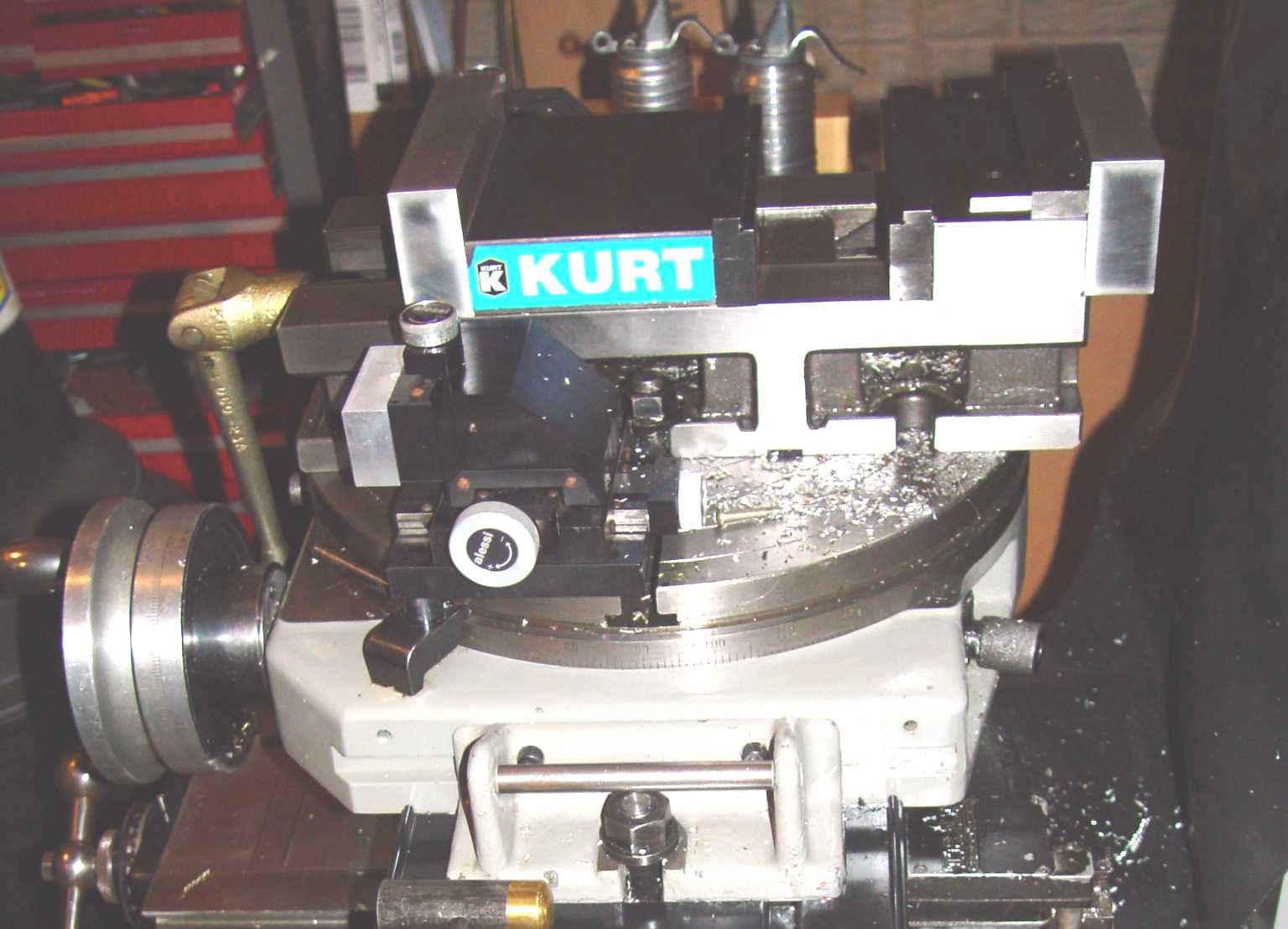
I"ve been thinking of getting a rotary table for use on my bridgeport, but haven"t fully formed an idea about what I really want. Based on what I"ve seen, I"m starting to think that I probably want to end up with 2, first a smaller one that would either do horizontal and vertical mounting or adjustable angle, probably in the 6-10" range (small enough that I can easily move), and then a larger one like a big, used bridgeport one for larger work.
Well, I got one as a gift for my birthday a couple of days ago (a PhaseII), and after getting a good look at it close up I realized that I"m probably going to end up returning this one and going with something else. The biggest thing is slot sizes... it has an indexing piece for use up on end that looks like it is intended for one slot size, and the slots on the table face are a smaller size, both smaller than the standard slots/holddowns that I have for the bridgeport. Seems like it would be a hassle mount it down to the table securely and then I"d need another set of hold down hardware just for use with the table.

Milling machines are the second most important machine tool in the shop. The Bridgeport-style vertical milling machine, also called a turret mill or a knee-and-column mill,and its miniature cousin, the Sherline milling machine, are among the most popular. There are more Bridgeport-style mills in use than all other designs combined because of their easy set-up, flexibility and cost-effectiveness. Although there are several small table-top mills available today, the many accessories available for the Sherline make it a good selection for this study. These smaller machines, often calledbox mills, lack the moveable quill of a full-sized Bridgeport, but they are an excellent choice for smaller work, smaller workshops and smaller budgets. See Figure 8-1.
Milling machines developed from rotary files, circular cutters with small file-like teeth that run in a lathe headstock. Rotary files date from the 1760s and were developed to reduce the time and effort of hand filing.
The early 1800s saw the first true milling machines. These machines used toothed rotary cutters turning on a horizontal axis and had table movement on the two horizontal axes, now called the x- and y-axes. A drawback of these early milling machines was that they had no provision for vertical table movement and so the work had to be shimmed up to meet the cutter.
In the mid-1800s, John R. Brown of Brown and Sharp, introduced the universal milling machine.This was a distinct improvement because its milling table swiveled around the vertical axis and had vertical table movement. A swiveling table allowed the cutting of helices with the table leadscrew geared to an indexing head, a giant step forward in cutting tool, drill and gear manufacturing. Also, the vertical table movement made for faster set-ups.
The early years of the 20th century ushered in more innovation in the form of anti-backlash leadscrew nuts that permitted coordinate positioning to 0.001 inches or better from a single reference point. This important development allowed parts to be made directly from prints rather than from jigs. By the 1930s, hydraulic tracer milling machines could make multiple parts by copying from a template. These two developments, coördinate positioning and pattern tracing, laid the groundwork for CNC machining, which began in the 1950s. The further refinement of horizontal milling machines led to the near extinction of shapers and planers since most of their work is now better done on a milling machine.
Another important development came in the 1930s when Rudolph Bannow and Magnus Wahlstrom brought out the Bridgeport vertical milling machine. Though traditional horizontal milling machines have higher metal removal rates, the Bridgeport design offers quicker set-up time, economy and versatility. Because of this versatility, there are more Bridgeport-style mills in existence today than any other milling machine design. Traditional horizontal mills are now usually reserved for production applications where high metal removal rates on identical parts are needed, not for prototypes and short runs.
The biggest advantage is the quill’s ability to advance and retract the cutter easily without cranking to raise and lower the milling table. This speeds production and reduces operator fatigue. The retractable quill lets the machinist quickly withdraw the tool to clear chips from a hole or to check its progress. Also, tactile feedback through the quill feed handle or handwheel tells the machinist how the tool is cutting and lets him optimize the feed rate with less danger of tool breakage. Vertical table movement is still available for high-accuracy depth adjustment or when more axial force on the tool is required.
The second largest advantage is the Bridgeport’s ability to make angle cuts. With the horizontal milling machine, either the milling cutter is made on an angle or the work must be positioned at an angle to the spindle axis. With the Bridgeport machine the operator merely needs to tilt the spindle to make an angle cut. Of course, with the Bridgeport you can also use an angled cutter or mount the work on an angle.
Vertical milling machines must use smaller cutting tools than horizontal mills because they have smaller, less rigid castings and lower horsepower motors. Still, vertical milling machines can accomplish the same end results as horizontal mills, just more slowly. Bridgeport-style milling machines usually have 1–5-hp motors and smaller castings than most horizontal mills, which often have 20–50-hp motors. Because of this, Bridgeports generally cost less.
In the last two decades, digital readouts (DROs) and CNC controls have been added to Bridgeport-style mills. With their additional capabilities, these machines can now engrave—drive the tool to cut numbers and letters in various sizes and fonts—cut radii and angles without a rotary table, make islands, pockets, and cut ellipses and frames. Entering the position, diameter and number of holes automates cutting a bolt-hole pattern; the system does the math. The computer can also automatically compensate for the reduced diameter of resharpened milling cutters, saving time and money, and improving accuracy. In addition, the computer control systems can be manually programmed through their control panels, use stored programs, “learn” new tasks by memorizing a series of manual operations as the operator makes the first part, or accept files from CAD programs.
A Bridgeport-style milling machine has nearly a dozen iron castings. Over time the dimensional stability of these castings is critical for machine accuracy. Because several of these castings are quite large, during production the outermost cast metal cools more rapidly than the internal metal, setting up internal stresses. These residual stresses gradually even out with time, but warp the castings in the process. This is why castings cannot be machined too soon after they are poured or bad things will happen.
The traditional method used to eliminate residual stress was to pour the castings, let them age outdoors in the weather for a year, then machine them. Bridgeport, as well as Rolls Royce, followed this practice. Twelve months of natural temperature cycling gave the cast iron a chance to work out its internal stresses and become dimensionally stable. Today, many quality machine builders use Meehanite castings, which are made according to a licensed process. By adding proprietary materials to the molten cast iron, solidification occurs with fewer internal stresses. These castings are dimensionally stable and ready to machine immediately. Machines made with the Meehanite process carry the logo in Figure 8-2 on the top front of the base casting. Poorer quality machines which do not use this process may experience dimensional changes in the first year or so of their lives.
When comparing different mills, always consider their weight. Milling puts large forces on machine castings, which can deflect the cutting tool out of alignment. When machine builders put more cast iron into their machines, rigidity and accuracy usually improve. One rough way to check a mill’s rigidity is to place a DTI on the milling table with the DTI’s foot against the spindle, then lean against the table or head and observe the indicator’s deflection. It should not deflect more than a fraction of one-thousandth of an inch. Smaller Bridgeport-style mills weigh in at 1650 lbs, larger manually-operated versions at 2800 lbs, and the CNC-equipped mills at nearly 4000 lbs. Heavier machines, because of their larger and more rigid castings, can use larger horsepower motors and can take larger cuts before chatter begins. Also, these machines can take large accurate cuts because of their rigid frames.
Although a few of the small Bridgeport-style mills have 8336-inch tables—that is, 8-inches wide and 36-inches long—full-size Bridgeport-style mills begin at 9349 inches and go up to 10350. Many CNC versions are 12350.
Motor horsepower has gradually increased over the years with the evolution of the Bridgeport-style mill. Early mills had ¼-hp motors, very small when you consider that a home vacuum cleaner has about 2 hp. Later mills went to 1 hp, then 2 hp, and today are mostly 3 and 5 hp. Eventually, even a low-power mill will get the job done, but a more powerful machine will get the job done quicker.
Early Bridgeport-style mills had belts and pulleys that produced eight spindle speeds—four in direct drive and four in backgear. To change spindle speed with this arrangement, the mill had to be stopped and the drive belt shifted from one pulley to another.
Variable frequency drives eliminate the confusing practice of running the spindle motor backward to get the spindle to turn forward when in backgear, as with the traditional Bridgeport-style design. With VFDs, forward is forward and backward is backward in direct drive or in backgear.

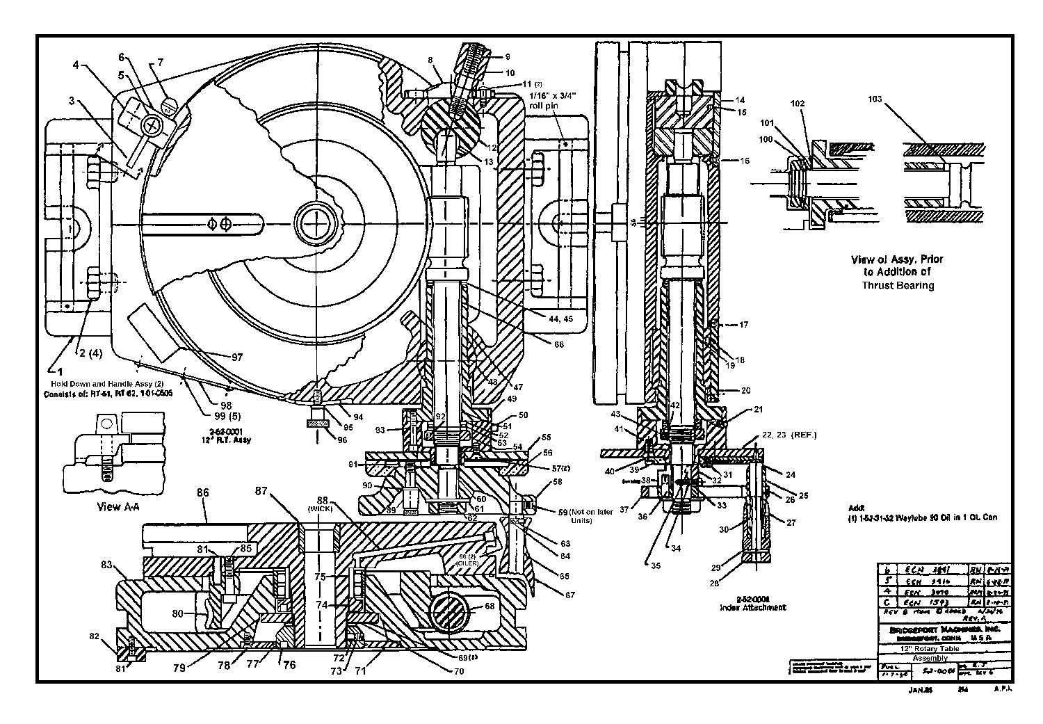
ROTARY TABLE, PARTICULARLY FOR MACHINE TOOLS Filed June 21, 1954 R. BELLMANN Oct. 8, 1957 4 Sheets-Sheet 1 INVENTOR REINHOLD BELLHRNN BY ROTARY TABLE, PARTICULARLY FOR MACHINE TOOLS Filed June 21, 1954 R. BELLMANN 4 Sheets-Sheet 2 931E. -33: a a $5. a
ROTARY TABLE, PARTICULARLY FOR MACHINE TOOLS v Filed June 21, 1954 4 4 Sheets-Sheet s INVENTOR i 1 EEKJJLVLKIIW ATTORNEY 4 Sheets-Sheet"4 R. BELLMANN INVENTOR REIggOLD Ball??? BY V "Mwa ATTORNEY ROTARY TABLE, PARTICULARLY FOR MACHINE TOOLS Filed June 21, 1954 ROTARY TABLE, PARTICULARLY FOR MACHINE TOOLS Reinhold Belimann, Le Locle, Switzerland, assignor to Dixi S. A., Le Lo"cle, Switzerland Application June 21, 1954, Serial No. 438,227 Claims priority, application Switzerland July 2, 1953 Claims. (Cl. 74824) This invention relates to a rotary table which can alternately be clamped, released and finely adjusted and which is particularly used in machine tools such as, for instance, horizontal boring and milling machines, dividing or indexing machines and the like. 7
Prior rotary tables of that kind comprise separate control means for clamping and releasing the table and for the fine adjusting device, one of these control means, such as a lever or"the-like, serves for clamping and releasing, 1 and the other control means, for instance, for swinging a worm of the fine adjusting device into and out of engagement. These prior solutions are uncomfortable in manipulation and injurious to accuracy. I
The above-mentioned and other inconveniences are done away with by the invention in that the rotary table according to the invention has only one control means,
the fine adjusting device. Due to the invention it is also possible to clamp the rotary table exclusively by springs so thatno force components in the rotary plane of the table occur. Moreover, .due .to the. springsthe clamping pressure is uniformly distributed.
The rotary table according to the invention may for instance be used in a machine as a rotary machine table and/ or as a top or set up table or the like.
Fig. 1 is a perspective view of some parts of a hori zontal precision boring and milling machine, and of an auxiliary table attachment temporarily mounted on the rotary machine table.
Fig. 2 is a vertical section of the auxiliary attachment through the rotary axis of its rotary table. 7 Fig. 3 illustrates an antifriction bearing and a control surface cooperating with the bearing, these means belonging to a mechanism controlling the clamping de vice for the rotary table of the auxiliary attachment.
atent O riage 3. Besides the adjustment means 10, 11 an optical means (not shown) may be provided for adjusting the angular position of the rotary machine table 7, such as for instance a. precision rule which may be read by means of a microscope or projected onto an image screen. Control lever 12 pivoted on the carriage 3 serves for: clamping fast the table 7 after angular adjustment of the latter. The tool 15 is fixed to the rotary hollow spindle 14 which is journalled on the drill head 13 of the machine and surrounds the axially adjustable drill spindle (not shown). The above-described parts of a horizontal boring and milling machine and their structural arrangement and interrelation are well known to those skilled in the art and, therefore, need no further detailed description and illustration.
An auxiliary set up or top attachment 16 is provided to be temporarily clamped to the rotary machine table 7 either in an upright or vertical position or in a hori-: zontal position. The auxiliary attachment is designed in accordance with applicants copending patent applica tion of even date, Serial Number 438,226, bearing the title Top table with a rotary plate, particularly for use in machine tools. The attachment 16 has a casing 17 of rectangular shape in plan view, and a circular rotary table 18 journalled on the casing 17 and provided with clamping grooves 19 and an outer circular graduation or division 20 cooperating with a mark 21 of the casing 17 for coarse hand adjustment of the angular position of the rotary table 18.
. v Thecasing 17 has laterally open slots 25 to receive clamping or holding-down bolts 26 held in a well-known manner in the grooves 8 of the machine table 7, the attac hment 16 being clamped by the bolts 26 to the machine table 7 in the position desired for the operation or operaf tions to be done.
In order to obtain a suitable rotary mounting of the table 18 on the attachment casing 17 a bearing or collar 37 integral with the plate 27 extends from the latter through the hollow space 35 down to the level of the front face 22 of the casing 17. A turning pin 40 is journalled in the bearing 37 and is held in axial direction by means of a disc 38 and a .bolt 39. The rotary table 18- is fixedly secured to the turning pin 4 In order that the table 18 may also be useful for precision work, the following provisions are taken to I satisfactorily clamp the rotary table 18 after its adjustcontrolling the fine adjustment drive for the rotary. table ment to the desired angular position, that is, to provide for the clamping effect withstanding all the forces applied to the workpiece during machining and to avoid any change of the adjusted angular position of the top table by the clamping operation.
For that purpose, clamping bolts 41 (e. g. two, three" or more bolts) distributed on an imaginary circle around the pin 40 are guided for axial movement in sleeves 42 of the casing plate 27 and are parallel to the axis ofrotation of the table 18 (Figs. 2 and 5). The bolts 41 comprise shoes 43 lying above a flange 44 of a ring 45 fixed to the rotary table 18. An adjustable compression spring 47 of for instance about 500 kilograms elastic forceis inserted between the flange of each sleeve 42 and an adjusting nut 46 of the respective bolt 41 and" presses the bolt 41 in the direction towards a lever 48. pivoted on the casing 17 as at 49. The lever 48 of each" bolt 41 is disposed in such a way that it transmits its force to the bolt 41 only in the axial direction ofthe latter. The free end of each pivoted lever 48 carries I an antifriction bearing 59 (see also Fig. 3) engaging a rotary control disc 51 coaxial to the rotary table 18. The control disc 51 comprises depressions 52 and even" surface portions 53 lying at a higher level than the de;
A circular scale I pressions 52. The control disc 51 is rotatably supported by means of antifriction bodies 54 such as rolls or balls running on a thrust plate 55 fixed to the bearing 37, and is linked by means of a rod 58 and an intermediate lever 59 to a control lever 57 accessible from the outside and pivoted on the casing 17 as at 56. If the control disc 51 is turned around the rotary axis of the table 18 by means of the control lever 57 so that the antifriction bearings 50 engage the depressions 52, the pivoted levers 48 are in their lowermost position and the shoes 43 are pressed only by their springs 47- against the inner front face of the flange 44 and clamp the rotary table 18 fast in its adjusted angular position. In this clamped position the bolts 41 do not contact their levers 48, Since the springs 47 exert only forces vertical to the rotary plane of the table 18 and since there is no positive connection be: tween the bolts 41 and their control means, clamping the rotary table 1 8 is obtainedwithout any force component in the rotary plane of the table 18,"wh ich could change the position of the plate by a small; amount during the clamping operation. Since clamping is only effected by means of springs 47, the clamping "pressure is also uniformly distributed on all bolts 41 The levers "48 merely serve for releasing the rotary table 18. The antifriction bodies 54 and bearing 50 considerably facilitate the operation of. the clamping device relatively to the well-known constructions comprising eccentrics, threade ing, worm gears etc.
For increasing the indexing or dividing accuracy and for maintaining the same over a long period, the attachment 16 with the table 18 is provided with an optical indexing or dividing attachment comprising an innera n nular. precision rule 60 fixed to the rotary"table 18 and:
readable from the outside by means of a microscope 61 (Figs. 1 and 2). In another performance means"may be provided for projecting the rule 60 onto an image screen. For turning the rotary table 18 on anfoptical j fine adjusting operation, the following simple device is provided (Figs. 2 and S): The shaft of the fine adjusting handwheel 62 (Figs. 1 and rotatably mounted on. the casing 17 carries a worm 63 engaging a worm wheel 64 keyed on a sleeve 66 loosely rotatable about a bolt 65 whose axis is parallel to the rotary axis of the table 18 (Figs. 2 and 5). A gear wheel 67" looselyarranged.
on the bolt 65 is permanently in mesh with a gear wheel 69 rigidly fixed to the hub 68 of therotary table 18. The axially adjustable bolt65 is under the influence of: a compression spring 70 of, e. g. about 5 kilograms elastical force, which may be adjusted by means of a nut 71- ofthe bolt 65. In Fig. 2, the bolt 65 under the constraint of the spring 76 bears againsta lobe 72 of" a radially projecting lug 73- of the control 511 so that thebolt 65 is in "liftedposition and the gear wheel.
67, on. a coarse hand adjustment of" th"e rotary "table 18, turns idly with the gear wheel-69, while the worm wheel 64 is at rest. When the control lever 57" is moved to the fine adjusting position it turns the controljdisc 51 in sucha direction that the lobe 72" comes out of reach of the bolt 65 and the spring 76 pushes the bolt 65"to-. wards the bottom so that the flange 74 of the bolt 65, which does now not contact the lug 73, presses the gear wheel 6 7tigh tly against the flange of the sleeve 66. Now; by turning the handwheel 62, the gear wheel67 is taken.
the rotary table 18 is turnedby thewheel 69 in accord ance with the angular movement of"the handwheel 62 For disengaging the fine adjusting drive the control"lever 57 is"adjusted until the lobe 72-lifts the bolts 6 5 again s t the constraint-of"the spring 76 7 In themodified fine adjusting drive shown in Fig.4
the; gear-wheel 67 is not taken along by the sleeve 6 6j by. frictional effect. The gear wheel 67 has crown teeth 7 75 engageable with and disengageable from crown teeth 76. of the flange 74-by axial adjustment of the bolt 65. The bolt 65 has a key.(not shown) runningin an axial groove (notshown) of the sleeve 66. so thatthe bolt is axially adjustable, but taken along in rotation by the sleeve 66. The remaining system of the fine adjusting drive of Fig. 4 is the same as in Fig. 2. In Fig. 4 the engaging force is, as in Fig. 2, only given by the spring acting vertically to the rotary plane of the table 18 so that the control lever 57 can be operated in any position of the rotary table 18, that is, also when the tips of the crown teeth contact the tips of the crown teeth 76.
Referring to Fig. 2, the springs 47 and 70 and their control means such as the parts 48, 51, 58, 59 with the exception of the control lever 57" lie within the hollow space or chamber 35,.
On the control lever 57 being in its mid-position as shown in Fig. 5, the antifriction bearings 50 contact the surface portions 53, of the control disc 51 and the-bolt 6 5, is out of reach of the lobe 72. Therefore, the rotary table 18 is not clamped and the fine adjusting drive is engaged and. fine adjusting by means of the handwheel 62 can take place. On adjusting now the lever 57 in the direction of the arrow A (Fig. 5), the depressions 52 of the control disc 51 come within reach of the antifriction bearings 50 and the levers 48 turn towards the bottom and the shoes 43 clamp the rotary table 18 fast under the influence of the springs 47. The belt 65 is still out of reach of the lobe 72 and the fine adjusting drive remains engaged. On moving now the control lever 57 back to its mid-position, the rotary table 18 gets again unclanrped. on adjusting; the control lever 57 from its mi d position in the direction of the arrow L (Fig.5) the ahtifriction bearings 50 remain on the surfaceportions 53 and the rotary table 18 remains unclarnped. However, the bolt 65 comes now in reach of the lobe 72 and the gear wheel 67 is disengaged from the worm wheel 64 so that the fine adjusting drive is uncoupled and the rotary table 18 is. freely rotatable such as, for instance,,by hand. Onreturning the control lever 57 to its mid-position the fine adjusting drive is again engaged While the rotary table 18 remains unclamped.
As described and shown, only one control lever 57 is provided for both clamping and; releasing the rotary table 18 and engaging and disengaging the fine adjusting device.
Referring now to Fig. 1, the attachment 16is shown in its upright or vertical position. A workpiece 79 is fixed to;the rotarytable 18 by means of clamps 77 and bolts 78 engagedin the grooves 19 of the table 18. On the workpiece 79 boreholes 80 are to be made, Whoseaxes lie on an imaginary conical surface with its axis .coinciding with the rotary axis of thetable 18. For
clampedto the machinetable; 170. In Fig. 6the controlle"verjfl of Figs. 2. and S is substitutedforithe cona t l er rll qi ia d heh n heersz or the, former example for the handwheel 9 of Fig. 1, lever 57 and handwheel 62 being mounted 0n; the carriage 3. The machine table which may be cornered or circplar, may be piyotallymounted on the carriage, "3 exactly in the sarne manner as" has been shown in Fig. 2 for the ma able 8 011 e a na i y me n ro fihe Pin 1.
Also the arrangement of the clamping bolts 41 with their springs 47 and pivoted levers 48 and of the control and drive means for the fine adjustment of the table 170 and their control by means of a control disc 51 mounted on antifriction bodies 54 and by means of the control lever 57 may be chosen as in Figs. 2 to 5 with the difierence that the attachment casing 17 is replaced by the hollow carriage 3 having an opening at the bottom. Also "the optical reading means 60,- 61 may be used. Therefore, illustrating in Fig. 6 the carriage 3 in section and showing therein all the parts and means of Figs. 2 to 5 (with the exception of the casing 17) has been dispensed with, as it would merely mean a


 8613371530291