
centering rotary table factory

As long as you do not move the table, you could indicate the part in by knocking it around until it sets in the same location. You could also spin the table itself and knock the part around to find its true center on the rotation of the table bearings. Some of the cheaper import rotary tables may not have the spindle bore as reliably on center as what they will rotate on their shaft.
The same indicator setup can check for spindle tram also. This will need to be checked periodically anyways to verify the spindle is perpendicular to the table surface. If the head is tilted and you indicate in a feature. If the point that it is indicated in at changes in height, so to will the location of the features you intend to machine in relation to that reference. The longer the tool bit is away from the indicated origin, the further off location the new feature will be. Where this is seen is when the part is indicated in at one level, but the distance between the spindle and work needs more room for the tool. So when the table drops away, the point of origin in relation the spindle center (being at an angle) is out lost in space now. The new feature(s) can be found way off location even though the table was moved correctly during the setup. Best advice is to keep this in mind if the knee or head will be moved in a Z axis, always check the tram first. Especially after a crash, broken cutter or large unexpected force at the cutter.

when your workpiece is placed on the rotary table, sweep the button with an indicator in the spindle, adjust position til your indicator zeroes out, and you"ll have it centred within the possible accuracy of the setup.

I often need to center my rotary table chuck under the quill of my Mill-Drill, and I found a quick way to accomplish the task. Center the two visually, then chuck a mechanical edge-finder with half in the drill-chuck (or collet) and the other end in the rotary table chuck. Be sure they are close to centered before tightening the edge-finder. Then slide your fingernail up & down over the mating joint of the edge-finder, while adjusting both X & Y planes, until your fingernail doesn"t catch an edge up or down over the mating joint, in either plane. Check it with a mich over the joint and it will be exact or extremely close to centered, depending on the degree of accuracy needed.

When using a rotary table on a mill, whether to mill an arc or drill holes in some circular pattern, there are two things that must be done to set up the workpiece. First, the workpiece must be centred on the rotary table. Second, the rotary table must be centred under the spindle. Then the mill table can be moved some appropriate distance and you can start cutting.
You could centre the table under the spindle first, by indicating off the hole in the centre of the table. Then you could mount the workpiece on the table and indicate off the workpiece. There are two problems with this approach. First, you are assuming that the hole in the table is true and centred. That may or may not be true. Second, this approach risks a sort of accumulation of errors, as you"re measuring from two different features (the rotary table"s hole and some feature on the workpiece). My suggestion is to centre the workpiece on the rotary table first, and then centre the rotary table under the spindle.
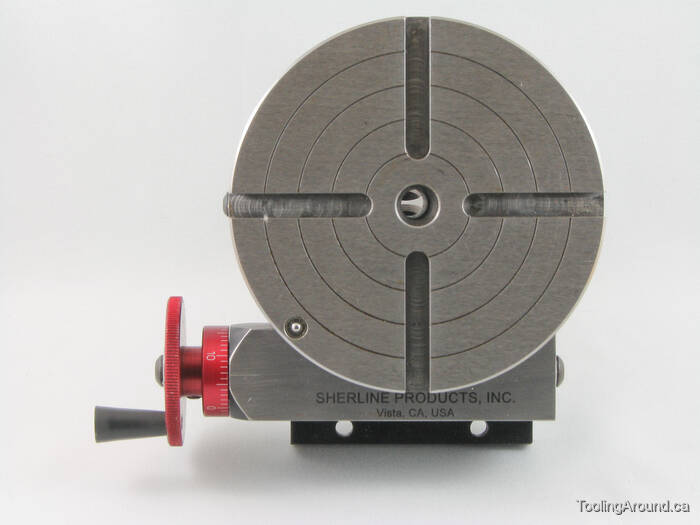
To centre the workpiece on the rotary table, spin the rotary table and watch for deflection of the indicator pointer. Adjust the chuck jaws as required, until the needle no longer deflects.
After the workpiece is centred on the rotary table, you now turn the spindle by hand, so the DTI tip sweeps the inside of the hole. Adjust the position of the mill table as required until no needle deflection is noted.
Again in this photo, a DTI is measuring from the inside of a hole. As in the previous illustration, the rotary table is spun and the workpiece"s position on the rotary table is adjusted until the DTI shows no deflection.
After the workpiece is centred on the rotary table, you now turn the spindle so the DTI tip sweeps the inside of the hole. Adjust the position of the mill table as required until no needle deflection is noted.
You can, of course, use the pointed end of a centre finder to position over a point on the workpiece. When centring the table under the spindle, if you are indicating off a larger hole or other curved feature, you may need to mount the indicator on a short arm, so you can sweep a large enough radius.
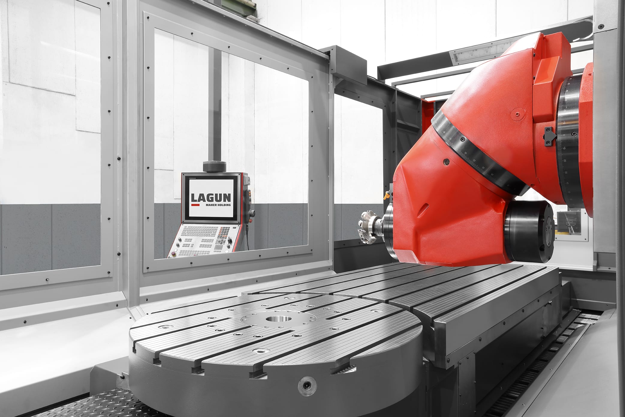
Is the rotary table axis above the X-Y slides as it appears? If you only need rotational motion you can flop it on your mill table anywhere convenient and clamp it down. Put a known circular object with enough weight not to move from indicator pressure on the table and get it centered by eye. Then with an indicator mounted anywhere convenient rotate the table and see how far out your object is. Tap it over toward center until you"re satisfied and now you have a circular table reference. Now mount the indicator in the spindle if it isn"t already, and move the mill"s X-Y to get your target object in line with the spindle.
If you trust the table"s outer rim sufficiently and your picture looks like rust could interfere, just mount the indicator in the spindle and with a sufficient extension sweep the rim.
If your rotary table is mounted close enough to the mill spindle centerline you could use the slides under it to re-position it sweeping the rim or your target.
For rough and ready location I stick a 2mt centre up the mills spout, then lower it into the centre bore of the table, lock the down feed and then tighten down the RT. Gets me close enough for most stuff.
Use a dial test indicator. Turn the dti from the head spindle. Turning the rotary table will not clock it true as the hole in the table will remain true. The dti must rotate.
An alternative would be to mount a short piece of ground bar in the spindle collet and mount the DTI an the rotary table in contact with the bar. Rotate the rotary table to align it. This would ensure that the axis of rotation of the table was aligned with the spindle. As I have DROs I would probably use an electrical edge finder in the spindle. I would first centre it roughly by eye. Then move say the X axis until the edge finder made contact with one side of the hole in the centre of the rotary table. Zero the DRO then move the table till the edge finder made contact with the other side of the hole. Then either use the centre function on the DRO or move the table back to half the reading. (and re zero the DRO if this is going to be your zero reference.) Repeat for the Y axis.
Hi - check out "Tom"s Techniques" website (http://tomstechniques.com). Under the section on Milling in the "Instructional Videos" dropdown he has a short video of how to "Center a Rotary table in Under a Minute Without an Indicator" - it doesn"t get much simpler and quicker than that!
I used to use "Osborne"s Maneuver", as detailed by Guy Lautard. You touch one side of the rotary table, and then move exactly half the diameter of the table. Then repeat on the perpendicular axis. Then repeat both axes. Three passes gives a neglible error. I now use a co-axial indicator on the centre hole:
I also set the rotary table to zero and align the T-slots to the axes of the mill; makes it a lot easier when cutting to specific angles. Of course all the methods assume that the rotary table, any centre hole, and the axis of rotation are concentric.
Most small rotary tables have some sort of center hole, sometimes with a cylindrical bore but often with a Morse taper. If the part you"re wanting to center has its own center hole, you might be able to make a plug that fits the rotary table center hole and the part center hole.
The more common way of centering a workpiece on a rotary table requires that you measure the difference between workpiece radii that are 180 degrees apart, and then adjust the workpiece location on the rotary table to split the difference. The most common tool used to make the measurements is a dial gage or dial indicator that must be held stationary; most often the dial gage is anchored to the machine spindle while the rotary table base is clamped to the table.
After you center the work on the rotary table by eye, set a dial indicator up to probe the reference surface. Adjust the indicator holder or move the table so that the dial gage plunger is pressed about half way into its range of travel before zeroing the indicator. Now turn the rotary table top and workpiece (as an assembly) a half turn before reading the dial gage.
Now you want to move the workpiece relative to the rotary table surface until the dial gage reads one-half of the second value. Let"s say your two dial gage readings are A. 0.000 inch, and B. 0.138 inch . . . you want to move the workpiece until the dial gage reads 0.069 inch at BOTH positions A and B.
Since it"s about impossible to move the part on the table exactly the right amount in the right direction, it"s vital that you recheck and readjust A and B after you adjust along C and D . . . and then you"ll need to check and readjust C and D again, and so on and so on. While you"re learning, it"ll seem like you"re chasing your tail, but it is a skill you"ll learn.
To reiterate, the important part is that when adjusting the part on the table you need to rotate the part and table together when you make your measurements, NOT the machine table.
Then later, if you need to center the table under the spindle, you rotate the spindle to measure and move the machine table, which has the rotary table and part bolted to it, to make the adjustment.
uxcell 3 Pcs Revolving Handwheel Machine Handle M6 Male Threaded Stem for Milling Machine , Jaw Self-Centering Metal Lathe Chuck Connecting Thread M121mm for Mini Lathe Accessories QOONESTL Z011 3/4 Jaw Lathe Chuck Connecting Rod , Factory 3 Jaw Self Centering Lathe Chuck 65mm with Backplate for 3" & 4" Rotary Tables - -, MT1 Live Tailstock Center with 60 Degree Cone For Use On Woodturning Lathes
it does not matter if a hole is tapered.(like the MT bore) it will be ground perpendicular to the bottom of the rotary table. so any point you swing an indicator in that bore will be true without showing any false elliptical path. another thing for visual is generally using a "to size" endmill for a slot gives you a good finish on one wall and a crappy one on the other...because the cutter is essentially climb milling on one side vs conventional on the other.
Typically you would use a 1/8 endmill and cut on center to clear out material.then at one end of the cut you would lift your cutter and move to the final spot you would end up at on the final cut taking out the backlash for the direction the next cut would be in of course. then raise the table so the cutter is in the slot again and dial your x or y axis in or out till you are at the opposite finish wall dimension. lightly lock the axis you were just moving. Then you would unlock and dial your rotary table to the other end of the slot and and lightly lock the rotary table. take out the backlash in the x or y axis screw while it is locked. then un-lock the axis screw and dial the axis the other direction in x or y to get to the finish spot on the second curved wall. then lightly lock the axis table lock. take out any backlash in the rotary table. do this by feel as you probably don"t have a rotary DRO. when the handle gets snug you"ve taken the slop out of the screw( on a new machine might only be a few thousandths)...do this gently or it will want to feed a bit when you unlock it because of the pressure you just added. then unlock your rotary table and dial it to the other end of the slot. and you are finished.


 8613371530291