
centering workpiece on rotary table manufacturer

then, to centre the workpiece itself, you first decide what accuracy level of centring you need.....just using a pointy mill wiggler in the spindle and aligning it with scribed lines on the workpiece can get you within .005 if you"re careful.
if you need to be closer, take a step back in history....."button up" the job with a toolmakers button......drill and tap for the button in the workpiece"s approx centre, snug up the button, adjust the button to the exact desired relationship with whatever surface or other feature of the workpiece defines your centre, and tighten up the button.
when your workpiece is placed on the rotary table, sweep the button with an indicator in the spindle, adjust position til your indicator zeroes out, and you"ll have it centred within the possible accuracy of the setup.

When using a rotary table on a mill, whether to mill an arc or drill holes in some circular pattern, there are two things that must be done to set up the workpiece. First, the workpiece must be centred on the rotary table. Second, the rotary table must be centred under the spindle. Then the mill table can be moved some appropriate distance and you can start cutting.
You could centre the table under the spindle first, by indicating off the hole in the centre of the table. Then you could mount the workpiece on the table and indicate off the workpiece. There are two problems with this approach. First, you are assuming that the hole in the table is true and centred. That may or may not be true. Second, this approach risks a sort of accumulation of errors, as you"re measuring from two different features (the rotary table"s hole and some feature on the workpiece). My suggestion is to centre the workpiece on the rotary table first, and then centre the rotary table under the spindle.
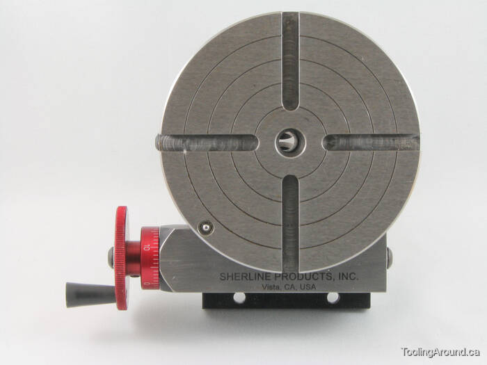
As shown in this photo, a DTI has been positioned with its tip against the inside of a hole in the workpiece. The DTI is held in the mill spindle, but that"s just for convenience. (When I do this, I put a little wooden wedge between the spindle pulley and the headstock, to make sure the indicator remains stationary.) It could as easily be held on a test stand. Indeed, the measurement doesn"t have to be done on the mill at all.
To centre the workpiece on the rotary table, spin the rotary table and watch for deflection of the indicator pointer. Adjust the chuck jaws as required, until the needle no longer deflects.
After the workpiece is centred on the rotary table, you now turn the spindle by hand, so the DTI tip sweeps the inside of the hole. Adjust the position of the mill table as required until no needle deflection is noted.
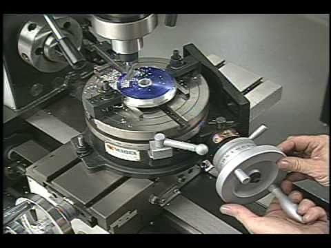
Again in this photo, a DTI is measuring from the inside of a hole. As in the previous illustration, the rotary table is spun and the workpiece"s position on the rotary table is adjusted until the DTI shows no deflection.
After the workpiece is centred on the rotary table, you now turn the spindle so the DTI tip sweeps the inside of the hole. Adjust the position of the mill table as required until no needle deflection is noted.
You can, of course, use the pointed end of a centre finder to position over a point on the workpiece. When centring the table under the spindle, if you are indicating off a larger hole or other curved feature, you may need to mount the indicator on a short arm, so you can sweep a large enough radius.

Most small rotary tables have some sort of center hole, sometimes with a cylindrical bore but often with a Morse taper. If the part you"re wanting to center has its own center hole, you might be able to make a plug that fits the rotary table center hole and the part center hole.
The more common way of centering a workpiece on a rotary table requires that you measure the difference between workpiece radii that are 180 degrees apart, and then adjust the workpiece location on the rotary table to split the difference. The most common tool used to make the measurements is a dial gage or dial indicator that must be held stationary; most often the dial gage is anchored to the machine spindle while the rotary table base is clamped to the table.
After you center the work on the rotary table by eye, set a dial indicator up to probe the reference surface. Adjust the indicator holder or move the table so that the dial gage plunger is pressed about half way into its range of travel before zeroing the indicator. Now turn the rotary table top and workpiece (as an assembly) a half turn before reading the dial gage.
Now you want to move the workpiece relative to the rotary table surface until the dial gage reads one-half of the second value. Let"s say your two dial gage readings are A. 0.000 inch, and B. 0.138 inch . . . you want to move the workpiece until the dial gage reads 0.069 inch at BOTH positions A and B.
Next, you need to repeat the measure-rotate 1/2 turn-measure-split the difference process at positions C and D, which must be on a line perpendicular to that connecting A and B.
Since it"s about impossible to move the part on the table exactly the right amount in the right direction, it"s vital that you recheck and readjust A and B after you adjust along C and D . . . and then you"ll need to check and readjust C and D again, and so on and so on. While you"re learning, it"ll seem like you"re chasing your tail, but it is a skill you"ll learn.
To reiterate, the important part is that when adjusting the part on the table you need to rotate the part and table together when you make your measurements, NOT the machine table.
Then later, if you need to center the table under the spindle, you rotate the spindle to measure and move the machine table, which has the rotary table and part bolted to it, to make the adjustment.
Is the rotary table axis above the X-Y slides as it appears? If you only need rotational motion you can flop it on your mill table anywhere convenient and clamp it down. Put a known circular object with enough weight not to move from indicator pressure on the table and get it centered by eye. Then with an indicator mounted anywhere convenient rotate the table and see how far out your object is. Tap it over toward center until you"re satisfied and now you have a circular table reference. Now mount the indicator in the spindle if it isn"t already, and move the mill"s X-Y to get your target object in line with the spindle.
If you trust the table"s outer rim sufficiently and your picture looks like rust could interfere, just mount the indicator in the spindle and with a sufficient extension sweep the rim.
If your rotary table is mounted close enough to the mill spindle centerline you could use the slides under it to re-position it sweeping the rim or your target.

I often need to center my rotary table chuck under the quill of my Mill-Drill, and I found a quick way to accomplish the task. Center the two visually, then chuck a mechanical edge-finder with half in the drill-chuck (or collet) and the other end in the rotary table chuck. Be sure they are close to centered before tightening the edge-finder. Then slide your fingernail up & down over the mating joint of the edge-finder, while adjusting both X & Y planes, until your fingernail doesn"t catch an edge up or down over the mating joint, in either plane. Check it with a mich over the joint and it will be exact or extremely close to centered, depending on the degree of accuracy needed.
Legal status (The legal status is an assumption and is not a legal conclusion. Google has not performed a legal analysis and makes no representation as to the accuracy of the status listed.)
Current Assignee (The listed assignees may be inaccurate. Google has not performed a legal analysis and makes no representation or warranty as to the accuracy of the list.)
Priority date (The priority date is an assumption and is not a legal conclusion. Google has not performed a legal analysis and makes no representation as to the accuracy of the date listed.)
Y—GENERAL TAGGING OF NEW TECHNOLOGICAL DEVELOPMENTS; GENERAL TAGGING OF CROSS-SECTIONAL TECHNOLOGIES SPANNING OVER SEVERAL SECTIONS OF THE IPC; TECHNICAL SUBJECTS COVERED BY FORMER USPC CROSS-REFERENCE ART COLLECTIONS [XRACs] AND DIGESTS
Y—GENERAL TAGGING OF NEW TECHNOLOGICAL DEVELOPMENTS; GENERAL TAGGING OF CROSS-SECTIONAL TECHNOLOGIES SPANNING OVER SEVERAL SECTIONS OF THE IPC; TECHNICAL SUBJECTS COVERED BY FORMER USPC CROSS-REFERENCE ART COLLECTIONS [XRACs] AND DIGESTS
Y—GENERAL TAGGING OF NEW TECHNOLOGICAL DEVELOPMENTS; GENERAL TAGGING OF CROSS-SECTIONAL TECHNOLOGIES SPANNING OVER SEVERAL SECTIONS OF THE IPC; TECHNICAL SUBJECTS COVERED BY FORMER USPC CROSS-REFERENCE ART COLLECTIONS [XRACs] AND DIGESTS
Y—GENERAL TAGGING OF NEW TECHNOLOGICAL DEVELOPMENTS; GENERAL TAGGING OF CROSS-SECTIONAL TECHNOLOGIES SPANNING OVER SEVERAL SECTIONS OF THE IPC; TECHNICAL SUBJECTS COVERED BY FORMER USPC CROSS-REFERENCE ART COLLECTIONS [XRACs] AND DIGESTS
Y—GENERAL TAGGING OF NEW TECHNOLOGICAL DEVELOPMENTS; GENERAL TAGGING OF CROSS-SECTIONAL TECHNOLOGIES SPANNING OVER SEVERAL SECTIONS OF THE IPC; TECHNICAL SUBJECTS COVERED BY FORMER USPC CROSS-REFERENCE ART COLLECTIONS [XRACs] AND DIGESTS
Y—GENERAL TAGGING OF NEW TECHNOLOGICAL DEVELOPMENTS; GENERAL TAGGING OF CROSS-SECTIONAL TECHNOLOGIES SPANNING OVER SEVERAL SECTIONS OF THE IPC; TECHNICAL SUBJECTS COVERED BY FORMER USPC CROSS-REFERENCE ART COLLECTIONS [XRACs] AND DIGESTS
Y—GENERAL TAGGING OF NEW TECHNOLOGICAL DEVELOPMENTS; GENERAL TAGGING OF CROSS-SECTIONAL TECHNOLOGIES SPANNING OVER SEVERAL SECTIONS OF THE IPC; TECHNICAL SUBJECTS COVERED BY FORMER USPC CROSS-REFERENCE ART COLLECTIONS [XRACs] AND DIGESTS
A centering and holding fixture includes a base, a piston disposed within a piston chamber at least partially located within the base, and a radially flexible ring connected to the piston by force transmission apparatus operable to contract and expand the radially flexible ring by upward and downward motions respectively of the piston. The flexible ring may be slotted and may include alternating inwardly and outwardly extending radial slots extending axially through the flexible ring and extending radially inwardly and radially outwardly from radially outer and inner surfaces of the flexible ring respectively to axial stress relief holes extending axially through the flexible ring. The apparatus may further be operable to contract the radially flexible ring when the piston chamber is pressurized and to expand it when the piston chamber is depressurized. Spring loaded clamps mounted to the base may be used to secure a workpiece to the holding fixture.
This application is a divisional of U.S. application Ser. No. 11/013,623, filed on Dec. 16, 2004, which is hereby incorporated by reference. FIELD OF THE INVENTION
This invention relates generally to multi axis machine tools such as vertical turret lathes (VTL"s) with rotary tables and, more particularly, to fixtures and chucks used to position and hold workpieces on the rotary table. BACKGROUND OF THE INVENTION
In most machining operations involving turning a workpiece, it is necessary to securely fix the workpiece in place upon a rotary table or other rotary work surface. Examples of such surfaces to which workpieces are secured include rotary tables, mill tables, fixtures or face plates and lathes, etc. Usually, the workpiece must be secured upon the surface to expose a selected portion of the workpiece upon which work such as cutting or machining is to be performed. In addition to securely fixing the workpiece in place, it is often necessary or desirable to provide fine adjustment in the position and alignment of the workpiece. For example, when a workpiece is secured to a rotary table, accurate alignment of a selected portion of the workpiece with the axial center of the rotary table is desired to facilitate and accurately conduct machine operations upon the workpiece.
Prior to any machining operations, it is necessary to align the part to be machined with the center of rotation of the machine tool. This is particularly difficult for machining large diameter workpieces, such as turbine rotors, on vertical turret lathes. Typically, such workpieces are held in 3-jaw or 4-jaw chucks which are mounted to rotary tables and aligned to the axis of the rotary table. Because of the critical nature of such workpieces, it may be necessary to align them to small tolerances such as within 0.002″ or less. This procedure is very time consuming and, therefore, very costly. SUMMARY OF THE INVENTION
A centering and holding fixture includes a base, a piston disposed within a piston chamber that is at least partially located within the base. A radially flexible ring is connected to the piston by a force transmission apparatus operable to contract and expand the radially flexible ring by upward and downward motions respectively of the piston. The flexible ring may be slotted and may include alternating inwardly and outwardly extending radial slots extending axially through the flexible ring and extending radially inwardly and radially outwardly from radially outer and inner surfaces of the flexible ring respectively to axial stress relief holes extending axially through the flexible ring. The apparatus may further be operable to contract the radially flexible ring when the piston chamber is pressurized and to expand it when the piston chamber is depressurized. Spring loaded clamps mounted to the base may be used to secure an annular workpiece to the holding fixture.
An exemplary embodiment of the force transmission apparatus includes an annular sleeve having a central bore coaxial with an upper counterbore in the annular sleeve. The central bore is wider than the upper counterbore and the central bore is separated from the upper counterbore by an upper annular ledge. A plurality of piston springs are circularly disposed within the upper counterbore in compression between the upper annular ledge and the piston. A piston extension rests on the piston and has a cylindrical extension shaft at least partially disposed within the bore and a downwardly tapering radially outer conical edge on the extension shaft. The radially flexible ring rests on a top of the annular sleeve and is disposed around the piston extension and at least a portion of the flexible ring has an upwardly tapering shape substantially conforming to the radially outer conical edge of the piston extension.
One more particular exemplary embodiment of the centering and holding fixture further includes an upper annular sleeve wall extending upwardly from the top of the annular sleeve. An extension head attached to the extension shaft radially overlaps the upper annular sleeve wall and has a downwardly tapering radially outer conical edge. The radially flexible ring resting on the top of the annular sleeve is disposed around the extension head. An annular lower portion of the flexible ring abuts and conforms to the upper annular sleeve wall and an upwardly tapering conical annular upper portion of the flexible ring substantially conforms to the radially outer conical edge of the extension head. BRIEF DESCRIPTION OF THE DRAWINGS
The foregoing aspects and other features of the invention are explained in the following description, taken in connection with the accompanying drawings where:
FIG. 1 is a schematical cross-sectional view illustration of a fixture to center a workpiece with respect to a rotational axis of a rotary table and hold and secure the workpiece to the rotary table.
Illustrated in FIG. 1 is a fixtured machining assembly 8 including an annular workpiece 14 mounted in a centering and holding fixture 10 fixedly attached to a horizontal rotary table 12 designed for rotation about a vertical axis C2 of a machine tool such as a vertical lathe (not illustrated). The fixture 10 is designed to releasably center and carry an annular workpiece 14 having a center axis C. The fixture 10 is designed for aligning the center axis C of the workpiece 14 with the vertical axis C2 of the rotary table 12. The fixture 10 includes a cylindrical base 16 relatively fixedly mounted to the rotary table 12.
The fixture 10 includes a radially outer support ring 30 which vertically supports the annular workpiece 14 and rests within a radially outer groove 31 illustrated herein as an outer annular rabbet 32 along a radially outer edge 33 in the base 16. An exemplary cylindrical piston 34 is disposed within an exemplary cylindrical piston chamber 36. A pressurized fluid supply passage 42 extends from an outer periphery 40 of the base 16 to the piston chamber 36. A fitting may be used for connecting a pressurized fluid hose to the supply passage 42. The fixture may use pressurized hydraulic fluid or pressurized air. An annular sleeve 50 fixedly attached to the base 16 rests in a radially inner annular rabbet 52 formed in a central cylindrical recess 54 in the base 16, the inner annular rabbet 52 being located radially inwardly of the radially outer annular rabbet 32.
The annular sleeve 50 has a central bore 56 and upper and lower counterbores 58 and 60, respectively, separated by a lower annular ledge 61. The lower counterbore 60 is upwardly bounded by a downwardly facing annular lower surface 62 of the lower annular ledge 61 in a lower portion 67 of the annular sleeve 50. The upper counterbore 58 is wider than the lower counterbore 60. The piston chamber 36 is bounded upwardly by a downwardly facing piston surface 63 of the piston 34 and downwardly by an upwardly facing inner circular surface 66 of the base 16 located within the recess 54, respectively.
The piston chamber 36 is bounded radially by a lower counterbore wall 70 that circumscribes the lower counterbore 60 in the annular sleeve 50. An annular gap 102 lies between the piston 34 and the lower counterbore wall 70. A piston ring 37 is disposed in a piston ring groove 39 in the piston 34 to seal against the lower counterbore wall 70. The upper counterbore 58 is upwardly bounded by an upper annular surface 74 on an upper annular ledge 75 separating the upper counterbore 58 and bore 56. A plurality of piston springs 76 are circularly disposed within the upper counterbore 58 in compression. The piston springs 76 are loosely mounted on piston spring pins 78 which are relatively fixed with respect to the piston springs 76 and illustrated as attached to the piston 34.
An upper annular sleeve wall 80 extends axially upwardly from a top 82 of the annular sleeve 50 and is radially inwardly bounded by the bore 56. A piston extension 86 includes a cylindrical extension shaft 88 disposed within the bore 56 and resting on the piston 34. An extension head 90 attached to the extension shaft 88 radially overlaps the upper annular sleeve wall 80. A radially outer conical edge 92 of the extension head 90 tapers downwardly. A radially flexible ring 94 rests on the top 82 of the annular sleeve 50 and is disposed around the extension head 90 attached to the extension shaft 88 and the upper annular sleeve wall 80 of the annular sleeve 50.
The flexible ring 94 is circumscribed about the vertical axis C2 and includes a cylindrical annular lower portion 96 that abuts and conforms to the shape of the upper annular sleeve wall 80. The flexible ring 94 includes a conical annular upper portion 98 that tapers upwardly and abuts and substantially conforms to the tapered shape of the radially outer conical edge 92 of the extension head 90. The cylindrical annular lower portion 96 and the conical annular upper portion 98 are circumscribed about the vertical axis C2. The conical annular upper portion 98 is stacked above, attached to, and entirely located above the cylindrical annular lower portion 96. FIG. 2 illustrates an exemplary embodiment of the flexible ring 94 that is slotted so that it is flexible in the radial direction. The flexible ring 94 includes alternating inwardly and outwardly extending radial slots 20 and 22 extending radially inwardly and radially outwardly from a radially outer and inner surfaces 24 and 26, respectively, to axial stress relief holes 28. The inwardly and outwardly extending radial slots 20 and 22 and the stress relief holes 28 extend axially through the flexible ring 94. Thus, fixture 10 provides a force transmission means for causing the radially flexible ring 94 to contract and expand by upward and downward motions respectively of the piston 34 illustrated in FIG. 1.
Referring to FIG. 1, the flexible ring 94 is pre-loaded along a conical surface 100 between the conical annular upper portion 98 of the flexible ring 94 and the radially outer conical edge 92 of the extension head 90. The tapered conical annular upper portion 98 of the flexible ring 94 is pre-loaded against the radially outer conical edge 92 of the extension head 90 such that when there is no pressure supplied to the piston chamber 36 or the piston chamber 36 is depressurized, the flexible ring 94 is radially expanded and centers and holds annular workpiece 14 in place for machining. When there is no pressure supplied to the piston chamber 36, the piston 34 is urged downwardly by the piston springs 76 which are compressively loaded between the annular sleeve 50 and the piston 34. The sleeve is fixedly attached to the base 16 of the fixture 10, thus, the piston springs 76 urge the tapered conical annular upper portion 98 of the flexible ring 94 against the radially outer conical edge 92 of the extension head 90 which radially expands the flexible ring 94.
The flexible ring 94 contracts when pressure is supplied to the piston chamber 36. The piston 34 moves upwardly working against a compressive force of the piston springs 76 when pressure is supplied to the piston chamber 36 causing the piston extension 86 to move upwardly. This causes the radially outer conical edge 92 of the extension head 90 to move away from the conical annular upper portion 98 of the flexible ring 94 allowing the flexible ring 94 to radially contract such that the annular workpiece 14 may be mounted in the fixture 10 attached to the rotary table 12. Thus, fixture 10 provides the force transmission means with the ability for causing the radially flexible ring 94 to contract when the piston chamber 36 is pressurized and to expand when the piston chamber 36 is depressurized.
Spring loaded clamps 110 have lugs 108 pivotably mounted on threaded pins 112 extending upwardly from the base 16. Clamp springs 114 are disposed in compression between the lugs 108 and clamp nuts 120 that are screwed on to the threaded pins 112. Once the workpiece 14 is positioned in place, the lugs 108 are pivoted to engage the workpiece and hold the workpiece in place. When the pressure to the piston chamber 36 is removed, the spring loaded lugs 108 hold the workpiece 14 in place.
While there have been described herein what are considered to be preferred and exemplary embodiments of the present invention, other modifications of the invention shall be apparent to those skilled in the art from the teachings herein and, it is therefore, desired to be secured in the appended claims all such modifications as fall within the true spirit and scope of the invention. Accordingly, what is desired to be secured by Letters Patent of the United States is the invention as defined and differentiated in the following claims.
a radially flexible ring connected to the piston by a force transmission means for causing the radially flexible ring to contract and expand by upward and downward motions respectively of the piston,
the radially flexible being ring including a conical annular upper portion stacked above a cylindrical annular lower portion and circumscribed about a vertical axis, and
4. A fixture as claimed in claim 1 further comprising the force transmission means being effective for causing the radially flexible ring to contract when the piston chamber is pressurized and to expand when the piston chamber is depressurized.
a radially flexible ring connected to the piston by a force transmission means for causing the radially flexible ring to contract and expand by upward and downward motions respectively of the piston and center and hold the annular workpiece in place for machining when the flexible ring is expanded,
the radially flexible being ring including a conical annular upper portion stacked above a cylindrical annular lower portion and circumscribed about a vertical axis, and
23. A fixtured machining assembly as claimed in claim 20 further comprising the force transmission means being effective for causing the radially flexible ring to contract when the piston chamber is pressurized and to expand when the piston chamber is depressurized.

This application claims priority to Japanese Patent Application No. 2011-002914 filed on Jan. 11, 2011 the disclosure of which, including the specification, drawings and abstract, is incorporated herein by reference in its entirety.
For example, US Patent Application Publication No. 2004/0038787 describes a machine tool that includes a centering jig attachable to a tool spindle and a runout measuring device that measures a runout due to decentering of a workpiece attached on a spindle. According to a workpiece centering method implemented by this machine tool, the runout measuring device measures the runout of the workpiece by turning the spindle. Then, the tool spindle is moved to press the centering jig against the workpiece. Based on the measured runout of the workpiece, the workpiece is pushed and centered by the centering jig.
According to the workpiece centering method described above, if the centering jig is excessively pressed against the workpiece and the axis of the workpiece passes beyond the rotation axis of the spindle, the workpiece is again decentered, resulting in another runout of the workpiece. That is, in such a case, due to the rotational force of the workpiece and the pressing force of the centering jig, the distance between the axis of the workpiece and the rotation axis of the spindle may further increase, and consequently, the workpiece may fall off the spindle.
One possible option for preventing the problem described above is to lower the speed at which the centering jig pushes the workpiece. This, however, is very time-consuming. Further, because the centering jig stops pushing the workpiece before the axis of the workpiece coincides with the rotation axis of the spindle, the runout of the workpiece is not completely eliminated, causing a certain degree of centering error.
Further, because the centering jig is attached on the tool spindle, a device that automatically switches the component attached on the tool spindle between the centering jig and a tool is required. Therefore, the switching work is very time-consuming. Further, because the centering jig is attached on the tool spindle, there is a possibility that the centering jig will come into contact with other member(s) as the tool spindle moves.
The invention provides a workpiece centering apparatus and a workpiece centering method that make it possible to easily perform accurate workpiece centering.
According to a feature of an example of the invention, a centering apparatus brings a position detection probe into contact with at least three circumferentially-offset points of a peripheral face of a workpiece on a rotary table, and measures the positions of the respective contact points between the position detection probe and the workpiece. Then, the centering apparatus calculates the amount of runout of the axis of the workpiece and a phase position of the workpiece, at which the runout amount is largest, based on the measured positions of the contact points on the peripheral face of the workpiece. As such, the position of the center of the workpiece and the radius of the workpiece are determined, and therefore the amount of runout of the axis of the workpiece with respect to the rotation axis of the rotary table and the direction of the runout are accurately determined. Subsequently, the centering apparatus turns the rotary table such that the largest runout phase position of the workpiece is set in a position opposed to the workpiece contact of the centering apparatus. Then, the centering apparatus determines the relative positions of the workpiece and the workpiece contact based on the positions of the contact points of the peripheral face of the workpiece and the position of the position detection block. As such, the relative positions of the workpiece and the position detection block are determined. Then, because the positional relation between the contact face of the position detection block and the contact face of the workpiece contact, which comes into contact with the workpiece, is known, the position of the workpiece contact relative to the workpiece is accurately determined. As a result of the processes described above, the positional relation between the workpiece, the rotary table, and the workpiece contact is determined, and then the centering shaft member of the centering apparatus is moved such that the workpiece contact pushes the workpiece by a distance corresponding to the runout amount. In this way, the workpiece is centered accurately.
According to another feature of an example of the invention, the centering apparatus is mounted on a bed on which the rotary table is provided, and therefore a device that automatically switches the component fitted to a tool spindle between a centering jig and a tool, which is conventionally required, is omitted, and thus it is no longer necessary to secure a mounting space for such an automatic switching device. Further, conventionally, a centering jig is provided at a tool spindle, and therefore there is a possibility that the centering jig contact other member(s) during movement of the tool spindle. According to the above-described example feature of the invention, on the other hand, there is no possibility of such a contact, and further the relative thermal displacements of the centering apparatus and the rotary table are reduced.
According to another feature of an example of the invention, the centering apparatus moves the position detection probe to a position that is on a side opposite, across the workpiece, to where the workpiece contact is present and that is a distance corresponding to the runout amount away from the outer peripheral face of the workpiece, and keeps the position detection probe in this position. Then, the centering apparatus moves the workpiece contact to push the workpiece until the peripheral face of the workpiece contacts the position detection probe. As such, the centering apparatus is able to determine that the workpiece has been accurately pushed by the distance corresponding to the runout amount, and this reduces the cycle time of the centering.
According to another feature of the invention, the centering apparatus is arranged such that the centering shaft member is inclined by a predetermined angle with respect to the movement direction of the position detection probe that is orthogonal to the rotation axis of the rotary table. This arrangement prevents a contact between the position detection probe and the centering apparatus during movement of the position detection probe. Further, the contact face of the position detection block, which comes into contact with the position detection probe, is formed such that the contact face extends in a direction orthogonal to the movement direction of the position detection probe. As such, the position of the position detection block is accurately detected.
The foregoing and further objects, features and advantages of the invention will become apparent from the following description of example embodiments with reference to the accompanying drawings, wherein like numerals are used to represent like elements and wherein:
A centering apparatus described in the following is used to center a columnar or cylindrical workpiece. As an example, a case where the centering apparatus is provided in a vertical grinding machine 1 will be described with reference to FIGS. 1A and 1B. Further, in the following example case, the cylindrical workpiece is centered when its outer peripheral face is ground by the vertical grinding machine 1.
As shown in FIGS. 1A and 1B, the vertical grinding machine 1 includes a bed 2, a rotary table 3, a column 4, a slider 5, a tool spindle head 6, a position detection touch sensor 7, a centering apparatus 8, and a control unit 9.
The bed 2 is generally rectangular, and is set on a floor. However, the shape of the bed 2 is not limited to a rectangular shape. The rotary table 3 and the centering apparatus 8 are mounted on the bed 2. The column 4 is provided upright at the rear side of the bed 2.
The rotary table 3 is circular, and is provided on the top of a rotation spindle 31 that is arranged at the bed 2 and extends vertically (i.e., in the Z-axis direction) such that the rotary table 3 is rotatable together with the rotation spindle 31. A rotation spindle motor 33 having a gear mechanism 32 that turns the rotation spindle 31 (rotary table 3) about the Z-axis is embedded in the bed 2. The rotation spindle motor 33 has an encoder used to detect the rotation angle of the rotation spindle motor 33. Therefore, it is possible to stop the rotation spindle 31 (rotary table 3) at a desired rotation angle position (phase). The workpiece is set on the rotary table 3, and magnetically fixed in its position.
The column 4 is shaped like a bridge, and is provided upright at the rear side of the bed 2. The control unit 9 is attached on one of leg members 41 of the column 4. The slider 5 is provided at an upper member 42 of the column 4.
The slider 5 is provided so as to be movable laterally (i.e., in the X-axis direction), that is, in the left-right direction as viewed in FIG. 1A, along a guide face 43 formed at the front side (face) of the upper member 42 of the column 4. A slider motor 52 that has a ball screw mechanism 51 used to move the slider 5 in the X-axis direction is provided at the upper member 42 of the column 4.
The tool spindle head 6 is provided so as to be movable vertically (i.e., in the Z-axis direction), that is, in the up-down direction as viewed in FIG. 1A, along a guide face 53 formed at the front side (face) of the slider 5. A tool spindle 61 extending vertically (i.e., in the Z-axis direction) is supported by the tool spindle head 6 such that the tool spindle 61 is rotatable about the Z-axis. A tool spindle motor 63 is embedded in the tool spindle head 6. The tool spindle motor 63 has a gear mechanism 62 that turns the tool spindle 61 about the Z-axis. A grinding wheel 64 used to grind the outer peripheral face of the workpiece is detachably attached at the lower end of the tool spindle 61. That is, the grinding wheel 64 is attached so as to be rotatable about the Z-axis relative to the tool spindle head 6.
The position detection touch sensor 7 is provided on the front face of the slider 5 so as to be movable vertically (i.e., in the Z-axis direction). Further, the position detection touch sensor 7 is movable also in a direction orthogonal to the rotation axis of the rotary table 3 as the slider 5 moves. The slider 5 is provided with a sensor motor (not shown in the drawings) having a ball screw mechanism used to move the position detection touch sensor 7 in the Z-axis direction. The position detection touch sensor 7 is provided with a position detection probe 71 extending downward (i.e., downward in the Z-axis direction). An axis Cp of the position detection probe 71, an axis Ct of the rotation spindle 31 (rotary table 3), and an axis Cg of the tool spindle 61 are aligned with each other on a line L extending in the X-axis direction.
The centering apparatus 8 includes a stationary portion 81, a movable portion 82, a centering shaft member 83, a workpiece contact 84, and a position detection block 85, which will be described in detail one by one. Because the centering apparatus 8 is mounted on the bed 2 on which the rotary table 3 is provided, a device that automatically switches the component attached on a tool spindle between a centering jig and a tool, which is conventionally required, may be omitted. Therefore, it is no longer necessary to secure a mounting space for such an automatic switching device. Further, conventionally, a centering jig is fitted to a tool spindle, and therefore there is a possibility that the centering jig may contact other member(s) during movement of the tool spindle. With the above-described structure of the example embodiment, on the other hand, there is no possibility of such a contact. Further, the relative thermal displacements of the centering apparatus 8 and the rotary table 3 are reduced.
The centering shaft member 83 is arranged in such a manner that the axis of the centering shaft member 83 passes through the axis Ct of the rotation spindle 31 (rotary table 3) and coincides with a line La that is inclined by a predetermined degree θ with represent to the line L. That is, the centering shaft member 83 is arranged in such a manner that the centering shaft member 83 is inclined by the predetermined angle θ with respect to the X-axis direction that is orthogonal to the rotation axis of the rotation spindle 31 (rotary table 3) and that is the direction in which the position detection probe 71 moves. This arrangement prevents a contact between the position detection probe 71 and the centering shaft member 83 during movement of the position detection probe 71.
The control unit 9 includes a centering controller 90 that controls the centering operation of the centering apparatus 8, and a grinding controller 91 that controls the grinding operation of the vertical grinding machine 1. However, it is to be noted that the centering controller 90 is not necessarily incorporated in the control unit 9, that is, the centering controller 90 may be provided outside the control unit 9. The centering controller 90 executes workpiece centering control by determining the runout of the axis of the workpiece from the axis Ct of the rotation spindle 31 (rotary table 3) through control of the rotation spindle motor 33, the slider motor 52, the sensor motor (not shown in the drawings), and a movable portion motor 87 b,which will be described later. The details of the workpiece centering control will be described later. The grinding controller 91 controls, through control of the tool spindle motor 63, etc., the grinding of the outer peripheral face of the workpiece by turning the workpiece and the grinding wheel 64 about the Z-axis while moving the workpiece and the grinding wheel 64 relative to each other in the Z-axis direction and X-axis direction.
Next, the details of the centering apparatus 8 will be described with reference to FIG. 2 schematically showing the structure of the centering apparatus 8. The stationary portion 81 is generally rectangular, and is fixed on the bed 2. The movable portion 82 is generally rectangular, and is provided on the stationary portion 81 such that the movable portion 82 is movable in the axial direction of the centering shaft member 83 (i.e., the direction of the line La). Paired movable portion guide rails 86 aand 86 b,which are parallel to each other, are provided on the top face of the stationary portion 81 so as to extend along the axial direction of the centering shaft member 83. The movable portion 82 is slidable on the paired movable portion guide rails 86 aand 86 b.
The stationary portion 81 is provided with a threaded shaft 87 aof a movable portion ball screw, which is arranged between the paired movable portion guide rails 86 aand 86 band is used to move the movable portion 82 in the axial direction of the centering shaft member 83. Further, the stationary portion 81 is provided with a movable portion motor 87 bused to rotate the threaded shaft 87 a.Further, a nut 87 cof the movable portion ball screw, which is screwed to the threaded shaft 87 a,is provided in the movable portion 82. Driven by the movable portion motor 87 b,the movable portion 82 moves along the paired movable portion guide rails 86 aand 86 b.The movable portion motor 87 bhas an encoder that detects the rotation angle of the movable portion motor 87 b.
The centering shaft member 83 is arranged so as to protrude from the rotary table 3-side end face of the movable portion 82 in such a manner that the axis of the centering shaft member 83 coincides with the line La. The centering shaft member 83 is movable, together with the movable portion 82, in a direction orthogonal to the rotation axis of the rotary table 3. The centering shaft member 83 may be stopped at a desired position by the movable portion motor 87 bhaving the encoder.
The workpiece contact 84 is a generally rectangular parallelepiped. The workpiece contact 84 is provided at the free end of the centering shaft member 83. Thus, as the centering shaft member 83 moves, the workpiece contact 84 comes into contact with the outer peripheral face of the workpiece and then pushes the workpiece in the radial direction of the workpiece.
The position detection block 85 is shaped like a rod. The position detection block 85 is provided so as to protrude from the lower side of the workpiece contact 84, at the free end of the centering shaft member 83, in a direction orthogonal to the axis of the centering shaft member 83. A contact face 85 awith which the position detection probe 71 may come into contact is formed at the free end of the position detection block 85, and is used to correct the position of the workpiece contact 84. The contact face 85 aextends in a direction orthogonal to the line L, that is, to the movement direction of the position detection probe 71. With the contact face 85 athus formed, the position of the position detection block 85 is detected accurately.
Next, the details of the centering controller 90 will be described with reference to the function block diagram of FIG. 3. Note that in the following descriptions on the centering controller 90, some of the structural elements of the vertical grinding machine 1 shown in FIG. 3 will be described as well. Further, note that in FIG. 3, the structural elements of the vertical grinding machine 1 shown in FIGS. 1A and 1B are denoted by the same reference numerals.
The centering controller 90 includes a shaft moving portion 92, a table turning portion 93, a probe moving portion 94, a workpiece peripheral face position measuring portion 95, a runout calculating portion 96, a block position measuring portion 97, a phase position indexing portion 98, a relative position deriving portion 99, and a pushing portion 100. The shaft moving portion 92 controls the driving of the movable portion motor 87 bto move the centering shaft member 83. The table turning portion 93 controls the driving of the rotation spindle motor 33 to turn the rotation spindle 31 (rotary table 3). The probe moving portion 94 controls the driving of the slider motor 52 to move the slider 5 (position detection touch sensor 7) in the X-axis direction, and controls the driving of the sensor motor to move the position detection touch sensor 7 (position detection probe 71) in the Z-axis direction.
The workpiece peripheral face position measuring portion 95 brings the position detection probe 71 into contact with at least three positions of the outer peripheral face of the workpiece, which are offset from each other in the circumferential direction, and measures the positions of contact points between the position detection probe 71 and the workpiece with the rotation of the rotary table 3 stopped. The runout calculating portion 96 calculates the amount of runout of the axis of the workpiece, and determines the phase position of the workpiece, at which the runout amount is largest (will hereinafter be referred to as “the largest runout phase position” where necessary), based on the peripheral face contact positions measured by the workpiece peripheral face position measuring portion 95. The block position measuring portion 97 measures the position of the position detection block 85 by bringing the position detection probe 71 into contact with the position detection block 85. The phase position indexing portion 98 causes the largest runout phase position of the workpiece to be opposed to the workpiece contact 84 by turning the rotary table 3. The relative position deriving portion 99 derives the relative positions of the workpiece and the workpiece contact 84 in a state where the largest runout phase position of the workpiece is opposed to the workpiece contact 84, which has been created by turning the rotary table 3, based on the contact positions measured by the workpiece peripheral face position measuring portion 95 and the position of the position detection block 85 measured by the block position measuring portion 97. The pushing portion 100 centers, after the above-described state is created by the phase position indexing portion 98, the workpiece by moving the centering shaft member 83, based on the relative positions determined by the relative position deriving portion 99, such that the workpiece contact 84 pushes the workpiece by an amount corresponding to the runout amount.
Next, the procedure of a centering program executed by the centering controller 90 will be described with reference to FIG. 4. The centering program is executed to control the operations of the centering apparatus 8, etc. so as to center the cylindrical workpiece set on the rotary table 3, as will be described in detail below.
As shown in FIG. 4, first, the centering controller 90 first moves the position detection probe 71 of the position detection touch sensor 7 toward the workpiece set on the rotary table 3 (step S1). Then, the centering controller 90 determines whether the position detection probe 71 has come into contact with the outer peripheral face of the workpiece (step S2). At this time, if it is determined that the position detection probe 71 has come into contact with the outer peripheral face of the workpiece, the centering controller 90 then measures the coordinates of the contact point (step S3).
Subsequently, the centering controller 90 increments a measurement number n by 1 (step S4), and then determines whether the measurement number n has reached a predetermined number N (step S5). The predetermined number N needs to be three or more in terms of determining the coordinates of the center of the circular outline of the workpiece and the radius of the workpiece. It is to be noted that the predetermined number N is set to four in this example embodiment.
If it is determined in step S5 that the measurement number n has not yet reached the predetermined number N, the centering controller 90 moves the position detection probe 71 away from the outer peripheral face of the workpiece, and then turns the rotary table 3 so as to rotate the workpiece by an angle of 2π/N (step S6). Then, the centering controller 90 returns to step S1, and repeats the processes in steps S1 to S4 until the measurement number n is determined as having reached the predetermined number N in step S5.
On the other hand, if it is determined in step S5 that the measurement number n has reached the predetermined number N, the centering controller 90 calculates the amount of runout of the workpiece and the phase position of the workpiece, at which the runout amount is largest, based on the measured coordinates of the contact points (step S7). For example, as shown in FIG. 5, in a case where the coordinates of four points at an outer peripheral face Wa of a workpiece W, i.e., the coordinates A (X1, 0) of a point A, the coordinates B (X2, 0) of a point B, the coordinates C (0, Y1) of a point C, and the coordinates D (0, Y2) of a point D of the outer peripheral face Wa are measured in an X-Y rectangular coordinate system with their origin at the axis Ct of the rotation spindle 31 (rotary table 3), the coordinates (α, β) of a center C of the workpiece W and a radius R of the workpiece W are calculated according to Equations 1 to 3 shown below.
A runout amount D of the workpiece W is (α ^ 2+β ^ 2)^ 0.5, and an intersection point P between the outer peripheral face Wa of the workpiece W and a line LL extending from the axis Ct of the rotation spindle 31 (rotary table 3) through the center C of the workpiece W is the largest runout phase position. As such, because the measured contact points of the outer peripheral face of the workpiece are equiangularly offset from each other (each angular interval is 90 degrees in this example embodiment), the runout amount of the workpiece and the largest runout phase position of the workpiece are easily determined. However, it is to be noted that it is possible to determine the runout amount of the workpiece and the largest runout phase position of the workpiece even if the positions (i.e., coordinates) of contact points of the outer peripheral face of the workpiece that are not equiangularly offset from each other are measured, that is, even if the angular intervals between the respective contact points are not equal to each other.
In step S8, the centering controller 90 determines whether the runout amount of the workpiece is equal to or smaller than a reference value that is prescribed for the workpiece centering. If the runout amount of the workpiece is equal to or smaller than the reference value, the centering controller 90 determines that the workpiece has been centered and therefore exits the centering program. On the other hand, if the runout amount of the workpiece is larger than the reference value, the centering controller 90 moves the position detection probe 71 away from the outer peripheral face of the workpiece, and then causes, by turning the rotary table 3, the largest runout phase position of the workpiece, corresponding to the intersection point P shown in FIG. 5, to be opposed to the workpiece contact 84 (step S9).
Subsequently, the centering controller 90 moves the position detection probe 71 and the position detection block 85 in such directions that the position detection probe 72 and the position detection block 85 contact each other (step S10). Then, the centering controller 90 determines whether the position detection probe 71 has come into contact with the contact face 85 aof the position detection block 85 (step S11). If it is determined that the position detection probe 71 has come into contact with the contact face 85 aof the position detection block 85, the centering controller 90 measures the coordinates of the contact face 85 a(step S12).
Then, because the positional relation between the contact face 85 aof the position detection block 85 and the contact face of the workpiece contact 84, which comes into contact with the workpiece, is known, the centering controller 90 derives the relative positions of the largest runout phase position of the outer peripheral face of the workpiece and the contact face of the workpiece contact 84, based on the coordinates of the contact points of the outer peripheral face of the workpiece and the coordinates of the contact face 85 aof the position detection block 85 (step S13).
Then, the centering controller 90 moves the workpiece contact 84 toward the workpiece such that the contact face of the workpiece contact 84 contacts the largest runout phase position of the outer peripheral face of the workpiece and pushes the workpiece by an amount corresponding to the runout amount (step S14). Subsequently, the centering controller 90 returns to step 1 and repeats the above-described processes of the centering program until the runout amount of the workpiece becomes equal to or smaller than the reference value. Through the processes described above, the workpiece W is centered accurately.
In the meantime, because the largest runout phase position of the workpiece is set to the position opposed to the workpiece contact 84 by turning the rotary table 3 in step S9, the relative positions are easily derived in step S13. However, it is to be noted that the angle by which the rotary table 3 is turned to bring the largest runout phase position of the workpiece to the position opposed to the workpiece contact 84 is obtained in advance, and therefore the process in step S9 may be executed after the process in step S13.
As described above, in the centering program, the position detection probe 71 is made to contact at least three circumferentially-offset points of the outer peripheral face of the workpiece on the rotary table 3, and the positions of the respective contact points between the position detection probe 71 and the workpiece are measured. Then, the amount of runout of the axis of the workpiece and the largest runout phase position of the workpiece are calculated based on the measured positions of the contact points on the outer peripheral face of the workpiece. As such, the position of the center of the workpiece and the radius of the workpiece are determined, and therefore the amount of runout of the axis of the workpiece with respect to the rotation axis of the rotary table 3 and the direction of the runout are accurately determined.
Subsequently, the rotary table 3 is turned so as to set the largest runout amount phase portion of the workpiece in the position opposed to the workpiece contact 84 of the centering apparatus 8. Then, the relative positions of the workpiece and the workpiece contact 84 are derived based on the positions of the contact points on the outer peripheral face of the workpiece and the position of the position detection block 85. As such, the relative positions of the workpiece and the position detection block 85 are determined. Then, because the positional relation between the contact face 85 aof the position detection block 85 and the contact face of the workpiece contact 84, which comes into contact with the workpiece, is known, the position of the workpiece contact 84 relative to the workpiece is accurately derived. As a result of the processes described above, the positional relation among the workpiece, the rotary table 3, and the workpiece contact 84 is determined. Therefore, the centering shaft member 83 of the centering apparatus 8 is moved such that the workpiece contact 84 pushes the workpiece by an amount corresponding to the runout amount. In this way, the workpiece is centered accurately.
Next, an interrupt program that may be additionally executed in step S8 of the centering program described above will be described with reference to FIGS. 6, 7A, 7B, and 7C. As shown in FIG. 6, the centering controller 90 moves the position detection probe 71 to the side opposite, across the workpiece W, to where the workpiece contact 84 is present (step S21). Then, the centering controller 90 determines whether the position detection probe 71 has come into contact with the outer peripheral face Wa of the workpiece W (step S22).
As shown in FIG. 7A. if the position detection probe 71 has come into contact with the outer peripheral face Wa of the workpiece W, the centering controller 90 then moves the position detection probe 71 to a position that is away, in the X-axis direction, from the outer peripheral face Wa of the workpiece W by a distance a corresponding to the runout amount D, and keeps the position detection probe 71 in the position (step S23), as shown in FIG. 7B. Then, the centering controller 90 moves the workpiece contact 84 toward the workpiece W so that the front end face of the workpiece contact 84 contacts a largest runout phase portion P of the outer peripheral face Wa of the workpiece W, and pushes the workpiece W toward the center C using the workpiece contact 84 (step S24).
Then, the centering controller 90 determines whether the outer peripheral face Wa of the workpiece W has come into contact with the position detection probe 71 (step S25). At this time, if it is determined that the outer peripheral face Wa of the workpiece W has come into contact with the position detection probe 71 as shown in FIG. 7C, the centering controller 90 finishes the interrupt program. In this way, through the interrupt program, the centering controller 90 is able to determine that the position detection probe 71 has pushed the workpiece W accurately by the distance corresponding to the runout amount D, and this reduces the cycle time of the centering.
The centering apparatus 8 is inclined by the predetermined angle θ with respect to the line L in order to prevent a contact between the position detection probe 71 that moves on the line L running in the X-axis direction and the centering apparatus 8 in the foregoing example embodiment. However, the centering apparatus 8 may be provided on the line L if a contact between the position detection probe 71 and the centering apparatus 8 is prevented by, for example, controlling the movement of the position detection probe 71.
Further, while the workpiece is centered through the centering program described above using the centering apparatus 8 in the foregoing example embodiment, the workpiece may be centered through the centering program described above using a runout prevention apparatus or a shoe grinding machine, which is often used to machine a workpiece on the basis of its outer diameter, in place of the centering apparatus 8.
Further, while the centering is performed on the basis of the outer diameter of the workpiece to grind the outer peripheral face of the workpiece in the foregoing example embodiment, the centering program described above may be implemented in the same manner as above also when the workpiece is centered on the basis of the inner diameter of the workpiece to grind the inner peripheral face of the workpiece.
Further, while the position detection touch sensor 7 is provided at the slider 5 in the foregoing example embodiment, for example, the same effects and advantages as those described above may be obtained even if a position detection touch sensor having a device for moving the sensor in the X-axis direction is used in place of the position detection touch sensor 7. In this case, for example, the position detection touch sensor is provided at the bed 2.
I often need to center my rotary table chuck under the quill of my Mill-Drill, and I found a quick way to accomplish the task. Center the two visually, then chuck a mechanical edge-finder with half in the drill-chuck (or collet) and the other end in the rotary table chuck. Be sure they are close to centered before tightening the edge-finder. Then slide your fingernail up & down over the mating joint of the edge-finder, while adjusting both X & Y planes, until your fingernail doesn"t catch an edge up or down over the mating joint, in either plane. Check it with a mich over the joint and it will be exact or extremely close to centered, depending on the degree of accuracy needed.
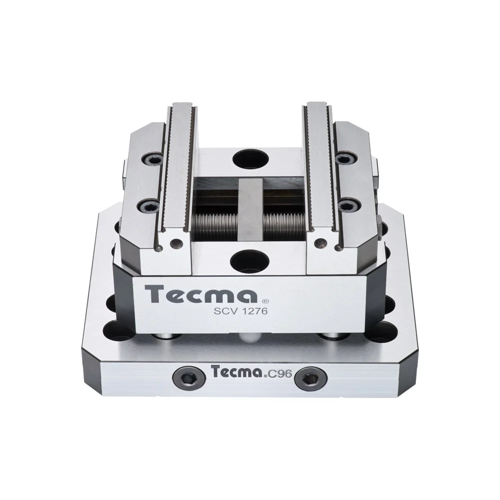
Mounts directly to a rotary table, Fixture Pro® Riser or any QLS Grid. Reduces distortion of parts like standard vises. Requires very little material (0.060” or less) to clamp. By cutting a 10º angle ...
Mounts directly to a rotary table, Fixture Pro® Riser or any QLS Grid. Reduces distortion of parts like standard vises. Requires very little material (0.060” ...
... gripping equipment. Detailed documentation is provided on request.These vises are exclusively intended for use as a static locking unit (mounting on CNC rotary tables, with rotating tools); ...
... gripping equipment. Detailed documentation is provided on request. These vises are exclusively intended for use as a static locking unit (mounting on CNC rotary tables, with rotating ...
High pressure ARNOLD TWIN vices are capable of clamping two pieces simultaneously.- Accuracy of 0.01 mm in clamping repeatability.- Suitable for working in horizontal and vertical machining centres.- Grinding of all ...
With DirectIndustry you can: Find the product, subcontractor or service provider you need | Find a nearby distributor or reseller| Contact the manufacturer to get a quote or a price | Examine product characteristics and technical specifications for major brands | View PDF catalogues and other online documentation

Our product range includes single and multiple axes, tilt/rotating tables, and indexing and high-speed spindles. Additionally, we offer customized solution tables for customer requests or OEM projects.
Customer satisfaction is our highest priority. Due to a high degree of vertical integration, our customers have one point-of-contact and the guarantee that all components are manufactured and assembled to your specifications.
Even for EDM machines that have been in use for decades, we will work with you to determine the ideal rotary indexing table and/or rotating/indexing spindle solution.
Our state-of-the-art rotary indexing tables and customizable reference and clamping systems provide endless application possibilities and highly efficient solutions.
Customer satisfaction is our top priority. You specify the task and together we’ll find the optimal solution for your production challenges and products.

A CNC rotary table is the precision positioning accessory that can provide a reliable 4th axis or even 5th axis for modern machining centers. Utilizing a computer-controlled rotary table can turn the original 3-axis machine tools into 5-axis CNC machines, expanding the accuracy as well as decreasing the costs while performing complex machining operations at one time.
A CNC rotary table is the precision positioning accessory that can provide reliable 4 or even 5 axis cutting operation capabilities for modern machining centers. Utilizing it can turn the original 3-axis machine tools into 5-axis CNC machines, expanding the accuracy as well as decreasing the costs while performing complex machining operations.
Rotary tables typically have rigid frames and coatings, and also excellent torque capacity, which makes the small device flexible and effective for a wide variety of turning, milling, drilling, and more metalworking operations. The easy setup and seamless interface allow the operators to easily add the rotary table to fit their 4-axis or 5-axis applications. .
The working principle is similar to the basic rotary tables, which is to support the workpiece by accurately rotating the workpieces on the axis in order to locate the parts for high precision tooling. Under rapid rotation, which is driven by CNC instructions, the cutting tools of larger machine tools or machining centers can remove the material and add the feature to the products at exact intervals. On rotary tables, there are vertical and horizontal axes for various tools to perform these high-performance metalworks. To enhance the accuracy and flexibility, there are models that employ additional dividing plates and come with add


 8613371530291