
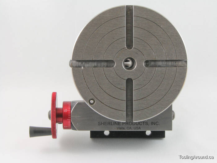
centering workpiece on rotary table factory

When using a rotary table on a mill, whether to mill an arc or drill holes in some circular pattern, there are two things that must be done to set up the workpiece. First, the workpiece must be centred on the rotary table. Second, the rotary table must be centred under the spindle. Then the mill table can be moved some appropriate distance and you can start cutting.
You could centre the table under the spindle first, by indicating off the hole in the centre of the table. Then you could mount the workpiece on the table and indicate off the workpiece. There are two problems with this approach. First, you are assuming that the hole in the table is true and centred. That may or may not be true. Second, this approach risks a sort of accumulation of errors, as you"re measuring from two different features (the rotary table"s hole and some feature on the workpiece). My suggestion is to centre the workpiece on the rotary table first, and then centre the rotary table under the spindle.
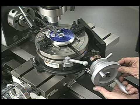
As shown in this photo, a DTI has been positioned with its tip against the inside of a hole in the workpiece. The DTI is held in the mill spindle, but that"s just for convenience. (When I do this, I put a little wooden wedge between the spindle pulley and the headstock, to make sure the indicator remains stationary.) It could as easily be held on a test stand. Indeed, the measurement doesn"t have to be done on the mill at all.
To centre the workpiece on the rotary table, spin the rotary table and watch for deflection of the indicator pointer. Adjust the chuck jaws as required, until the needle no longer deflects.
After the workpiece is centred on the rotary table, you now turn the spindle by hand, so the DTI tip sweeps the inside of the hole. Adjust the position of the mill table as required until no needle deflection is noted.
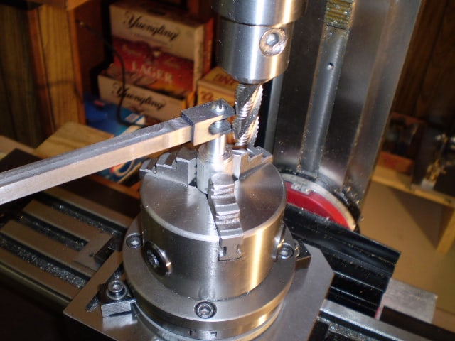
Again in this photo, a DTI is measuring from the inside of a hole. As in the previous illustration, the rotary table is spun and the workpiece"s position on the rotary table is adjusted until the DTI shows no deflection.
After the workpiece is centred on the rotary table, you now turn the spindle so the DTI tip sweeps the inside of the hole. Adjust the position of the mill table as required until no needle deflection is noted.
You can, of course, use the pointed end of a centre finder to position over a point on the workpiece. When centring the table under the spindle, if you are indicating off a larger hole or other curved feature, you may need to mount the indicator on a short arm, so you can sweep a large enough radius.

then, to centre the workpiece itself, you first decide what accuracy level of centring you need.....just using a pointy mill wiggler in the spindle and aligning it with scribed lines on the workpiece can get you within .005 if you"re careful.
if you need to be closer, take a step back in history....."button up" the job with a toolmakers button......drill and tap for the button in the workpiece"s approx centre, snug up the button, adjust the button to the exact desired relationship with whatever surface or other feature of the workpiece defines your centre, and tighten up the button.
when your workpiece is placed on the rotary table, sweep the button with an indicator in the spindle, adjust position til your indicator zeroes out, and you"ll have it centred within the possible accuracy of the setup.
Most small rotary tables have some sort of center hole, sometimes with a cylindrical bore but often with a Morse taper. If the part you"re wanting to center has its own center hole, you might be able to make a plug that fits the rotary table center hole and the part center hole.
The more common way of centering a workpiece on a rotary table requires that you measure the difference between workpiece radii that are 180 degrees apart, and then adjust the workpiece location on the rotary table to split the difference. The most common tool used to make the measurements is a dial gage or dial indicator that must be held stationary; most often the dial gage is anchored to the machine spindle while the rotary table base is clamped to the table.
After you center the work on the rotary table by eye, set a dial indicator up to probe the reference surface. Adjust the indicator holder or move the table so that the dial gage plunger is pressed about half way into its range of travel before zeroing the indicator. Now turn the rotary table top and workpiece (as an assembly) a half turn before reading the dial gage.
Now you want to move the workpiece relative to the rotary table surface until the dial gage reads one-half of the second value. Let"s say your two dial gage readings are A. 0.000 inch, and B. 0.138 inch . . . you want to move the workpiece until the dial gage reads 0.069 inch at BOTH positions A and B.
Next, you need to repeat the measure-rotate 1/2 turn-measure-split the difference process at positions C and D, which must be on a line perpendicular to that connecting A and B.
Since it"s about impossible to move the part on the table exactly the right amount in the right direction, it"s vital that you recheck and readjust A and B after you adjust along C and D . . . and then you"ll need to check and readjust C and D again, and so on and so on. While you"re learning, it"ll seem like you"re chasing your tail, but it is a skill you"ll learn.
To reiterate, the important part is that when adjusting the part on the table you need to rotate the part and table together when you make your measurements, NOT the machine table.
Then later, if you need to center the table under the spindle, you rotate the spindle to measure and move the machine table, which has the rotary table and part bolted to it, to make the adjustment.

Is the rotary table axis above the X-Y slides as it appears? If you only need rotational motion you can flop it on your mill table anywhere convenient and clamp it down. Put a known circular object with enough weight not to move from indicator pressure on the table and get it centered by eye. Then with an indicator mounted anywhere convenient rotate the table and see how far out your object is. Tap it over toward center until you"re satisfied and now you have a circular table reference. Now mount the indicator in the spindle if it isn"t already, and move the mill"s X-Y to get your target object in line with the spindle.
If you trust the table"s outer rim sufficiently and your picture looks like rust could interfere, just mount the indicator in the spindle and with a sufficient extension sweep the rim.
If your rotary table is mounted close enough to the mill spindle centerline you could use the slides under it to re-position it sweeping the rim or your target.

Once you find the center of the rt, sweep the work by locking the table x,y @ 0,0 and moving the work around if you have a center mark for the workpiece. If not, sweep the OD if it is round, or just plant an indicator to point on the work and dial the rt around until the work runs true.

Here is what I like to use as a test indicator holder. It can allow you to indicate in something without removing the tool. They have several options for in spindle or spindle nose clamp styles. eBay does have some cheaper import version that work ok, but once you have use the Indicol quality, there is a big difference. You will need to buy the test indicator as a seperate item. There are a lot on the market. I have had my B&S(brown and Sharp) "Best Test" indicator for almost 30 years and one repair. Reasonably rugged and very reliable. Sticky indicators like some imports do you no good. If the needle pointer does not move, it is inviting a false sense of security.
The whole premise is to use the spindle bearings to sweep an indicator around the surface you wish to align it to. It is much easier in concert with a DRO, but dials will get you there too.
As long as you do not move the table, you could indicate the part in by knocking it around until it sets in the same location. You could also spin the table itself and knock the part around to find its true center on the rotation of the table bearings. Some of the cheaper import rotary tables may not have the spindle bore as reliably on center as what they will rotate on their shaft.
The same indicator setup can check for spindle tram also. This will need to be checked periodically anyways to verify the spindle is perpendicular to the table surface. If the head is tilted and you indicate in a feature. If the point that it is indicated in at changes in height, so to will the location of the features you intend to machine in relation to that reference. The longer the tool bit is away from the indicated origin, the further off location the new feature will be. Where this is seen is when the part is indicated in at one level, but the distance between the spindle and work needs more room for the tool. So when the table drops away, the point of origin in relation the spindle center (being at an angle) is out lost in space now. The new feature(s) can be found way off location even though the table was moved correctly during the setup. Best advice is to keep this in mind if the knee or head will be moved in a Z axis, always check the tram first. Especially after a crash, broken cutter or large unexpected force at the cutter.
The same holds true for vises parallel to an axis. For critical work, always check the solid jaw for axis alignment. If it is at an angle and a feature is indicated in on one end of the jaws, it might not be at the other end. More or less exponentially to the angle it is off over XX distance from the origin.
Main objective here is to use as much of the machines built in geometry to maintain pure geometry on the part as the machines is capable of. A test indicator is the best way to obtain this level of precision.

When using a rotary table there are four simple steps that are invariably necessary. It is very easy to overlook the simplest alignments necessary. Most rotations will be with reference to some particular point. Usually this will mean setting the table to zero – the zero must be at the fiduciary mark.
Before doing anything else with a rotary table it is always worth setting it to zero. The table is turned so the fiduciary mark on the base is pointing to 0 degrees on the side of the rotating part.
If this is done it is unlikely that the zero on the dial lines up with the marker. This can usually be adjusted by rotating the part with the calibrations on it whilst holding the handle from moving..
Sometimes it is necessary to make cuts into a workpiece mounted on a rotary table by moving the table in the clockwise or anticlockwise directions and it is necessary to align the table so that such a cut occurs when the fiduciary mark on the table is at a particular angle to the milling table.
In this case the next step is to clamp the rotary table to the table. It might not seem obvious but, ideally, a line from the center to the fiduciary mark should be at right angles to the table. This is not as easy as one might imagine.
This device consists of a spigot that fits the hole on the rotary table. It has an arm fitted to it. One edge of this arm is aligned so it goes from the center of the rotary table to way beyond the edge of the rotary table. It has a clamp so it is bolted to the rotary table. It has a bit hanging down so it can be aligned at 270 degrees on the rotary table.
This arm can be aligned with the milling table using an angle plate and a square as shown above. The rotary table with the device attached is moved till it is square and is then clamped to the milling table.
If the rotary table has been “squared” then it will already be clamped to the milling table. In this case it is best centered using the DTI on an arm tool.
If it was not necessary to “square” the rotary table then it will not be bolted to the milling table. In this case the easiest way of aligning it with the spindle is by means of spigots.
The rotary table is now centered and aligned rotationally it is now possible to tighten the bolts up. Check the alignments still work ie the one in the milling chuck still slides in and out of whatever other spigot it is fitting into.
Whenever a chuck is mounted on a rotary table it will be necessary to align the rotary table at some point. Here the procedure is to align the rotary table as described above and then to fit the chuck as described next.
Firstly the chuck is mounted on a backing plate. This plate is of a larger diameter than the chuck and has slots in it so that it can be bolted onto the rotary table.
Ideally the plate should be machined so it has a raised round part that will fit accurately into the recess on the back of the chuck. This is not to align the chuck but to make sure it is truly fixed in position. Where the chuck fits on this plate is not critical. The plate is bolted onto the back of the chuck. The plate has a hole in it so that the hole in the center of the chuck is exposed.
The chuck with it backing plate is mounted on the rotary table loosely. A spigot is fitted in the jaws of the chuck. Remember the rotary table is aligned and locked so that it is aligned with the spindle.
It will probably be necessary to make bolts specially to bolt the chuck/plate assembly to the rotary table. It is worth keeping them and the spigot(s) together with the chuck/plate assembly when not in use.
Having aligned the rotary table the next step is to mount the workpiece on it. This will need aligning relative to the rotary table’s center and its zero.
A workpiece might have several different radii to be cut on it, but with a common center. So the workpiece only needs to be centered once on the rotary table. But for every radius that has its own center, then the workpiece will have to be moved on the rotary table so the center of the required radius is concentric with the hole in the rotary table.
Some rotary tables have some arrangement that allows for a bolt to be retained underneath the hole in the center of the rotary table. If this is the case then, if there is a suitable hole in the spigot, this can be used as one of the clamps.
Mark the center of the radius on the workpiece with a punch. Center the rotary table with the axis of the spindle. This means moving the milling table till both the readings on both the x and y DRO’s are zero. Lock in both the x and y directions.
Make a spigot that fits the hole in the rotary table. Make a center in it using a spot drill in the lathe. Set a pair of dividers to the required radius. Set the workpiece so that whatever the length of the arc, the distance from the center in the spigot is the same to both ends of the arc. If the sector is not more than 90º use the two ends. If the sector is from 90º to 180º use two ends and the middle. If the sector is 180º-360º use the middle and two at 90º to the middle.
The height of the point of the divider on the rotary table should not be greatly different to height of the surface of the workpiece. If the height of the surface is significant then make the spigot so that the height of the top of the spigot is roughly the same as the surface being centered.
The surface of an angle plate can be aligned with the center of a rotary table by making a spigot that fits the rotary table at one end. The other end has half of it milled away to give a surface that passes through the center of the spigot.
If the surface of the angle plate does not pass through the axis of the rotary table then as the rotary table rotates the position of all points on the angle’s surface will move.
It will be noticed that aligning a round workpiece has not been covered here because it is far easier to mount a round workpiece on a rotary table using a chuck.
However sometimes a circle of holes is needed in a part that is not round or where the center of the circle of holes is not concentric with a circular part. Parts such as cylinder covers need a circle of holes but are not necessarily circular. In this case the workpiece might be clamped directly onto a rotary table.
At the same time, the workpiece needs aligning with the milling table. One way of doing this is to clamp a long parallel to the workpiece along any reference line. The center is aligned with the spindle. The workpiece is rotated till the parallel is lined up parallel or at right angles to the milling table using the parallel, angle plate, square method.
The workpiece is clamped to the rotary table. Unlock the x-axis. Move along the x-axis by the amount of the radius of the circle of holes. Clamp x-axis.
To set the pitch circle diameter the chuck rotary table combination has to be set so it is concentric with the axis of the spindle. The movement in one direction, probably the y direction is locked. The backlash in the x direction is taken up one way. The x dial or x-axis DRO is set to zero. Half the pitch circle diameter, in the direction the backlash was taken up, moves the table. The movement in the x direction is then locked.
If the “vertical” rotary table is achieved by mounting a rotary table on an angle plate the it can be useful to have an angle plate that is machined flat on the inside angle of the angle plate. This can save space on the milling table.
Often the height needs to be set to a specific value. To do this fit a spigot, of a convenient diameter, to the rotary table. Place the angle plate with the rotary table loosely mounted on it on a surface plate.
If this assembly is “top heavy” then place it near the edge of the surface plate so the angle plate can be clamped to the edge of the surface plate using a toolmaker’s clamp. Place a stack of slip gauges of the height necessary underneath the spigot. Tighten the bolts holding the rotary table.
All of this is positioned so that the cutting tool is the radius of the arc to be cut from the axis of the large rotary table. The milling table is then locked in both the x and y directions.
The start and end points of each arc are simply determined two angles on the bottom rotary table. How many slots there are and where they are determined by the angle of the top rotary table.

A CNC rotary table is the precision positioning accessory that can provide a reliable 4th axis or even 5th axis for modern machining centers. Utilizing a computer-controlled rotary table can turn the original 3-axis machine tools into 5-axis CNC machines, expanding the accuracy as well as decreasing the costs while performing complex machining operations at one time.
A CNC rotary table is the precision positioning accessory that can provide reliable 4 or even 5 axis cutting operation capabilities for modern machining centers. Utilizing it can turn the original 3-axis machine tools into 5-axis CNC machines, expanding the accuracy as well as decreasing the costs while performing complex machining operations.
Rotary tables typically have rigid frames and coatings, and also excellent torque capacity, which makes the small device flexible and effective for a wide variety of turning, milling, drilling, and more metalworking operations. The easy setup and seamless interface allow the operators to easily add the rotary table to fit their 4-axis or 5-axis applications. .
The working principle is similar to the basic rotary tables, which is to support the workpiece by accurately rotating the workpieces on the axis in order to locate the parts for high precision tooling. Under rapid rotation, which is driven by CNC instructions, the cutting tools of larger machine tools or machining centers can remove the material and add the feature to the products at exact intervals. On rotary tables, there are vertical and horizontal axes for various tools to perform these high-performance metalworks. To enhance the accuracy and flexibility, there are models that employ additional dividing plates and come with additonal material handling mechanisms and features.
Since 4-axis and 5-axis machining is increasingly popular today, adding the CNC rotary table as the 4th axis is an ideal solution to easily open up more complex machining options at a lower cost. Due to the arrangement, they are widely also called the 4th or 5th axis or tilt rotary. The 4th axis, which is the rotational operational direction, is added to the original three linear axes which are known as X-axis, Y-axis, Z-axis. In some cases, there are two rotational axes add to the original 3-axis machining center, achieving utmost accuracy as well as effective multiple face cutting to reach the difficult area on the surface. Rotary tables are usually mounted parallel to the ground or the bed, with the platter rotating around the vertical axis, for example with the most common vertical milling machine combination. Sometimes the machining application requires an alternative setup with the table mountet on its end so that it rotates around the horizontlal axis. Often, a tailstock is used in this configuration. Virtually all models today come with a clamping kit to mount it onto the bed of your machine tool.
The function of the high precision rotary table is also to rotate the workpiece so the cutting tool can create the contour we desired out of the workpiece. However, a rotary table with higher precision has the ability to achieve great accuracy just as its name implies. There is also a major misconception between the resolution and the accuracy.
A common example is that if a digital readout displays to four decimal places, then the high precision rotary table must also be capable of achieving the accuracy to that same value. Even though for higher accuracy to be achieved, the resolution has to also be high, but there is no guarantee that the accuracy is going to be high. The accuracy is the concept which is the difference between the actual position and the position measured by a reference measurement device. The feedback mechanism such as the rotary encoder, and the drive mechanism can influence the accuracy of the advanced rotary table.
A CNC rotary table can provide great rigidity for stable machining operations. It consists of the worktable where the metal parts are held, the rigid bearing that withstands the forces and loads during the rotation, the solid base which is used for attaching the rotary table to the machining center or other equipment, the motor, and the CNC system.
The worktable is the tooling surface where the workpieces are machined after accurate positioning. The worm gearing is the core mechanism of the table, which mesh with the steel worm which is submerged in the lubricants. Both the rigid bearings and the worm gears have large diameters. Excellent concentricity is the key to smooth operation, durability, and most importantly, accuracy. Driven by a computer and electric motor, the worktable can position the materials at exact intervals. For more flexible or critical operations, dividing plates can be added to this component.
A CNC system regulates the simultaneous 4-axis motion of the rotary table. The instructions are programmed and transmitted via CAD software, reducing the time for adjustment and monitoring by human workers.
The type and size of the electric motors utilized in can define the router accuracy as well as the efficiency of the device. Servo motor and stepper motor are two typical types that can be divided into more subtypes. The servo motor uses a closed looping variable circuit, the circuit will constantly run to keep the function. The brushes must be replaced every 2000 hours of operation in the servo motor. Compared to stepper motors, servo motors are more efficient in power consumption. On the other hand, the stepper motor has a simpler setup which are the wires that are attached to the driver. The bearing of the stepper motor is the only wearing component. However, the stepper motor consumes a great amount of energy.
There are currently several different types and models available in the industries. Each of them possess its own traits and abilities. Let us take a look at the most common ones other than standard three axis tables
The 4 axis CNC rotary table will process the workpieces by holding them in the same position while the cutting tool performs along the XYZ plane to trim away the unwanted material. In general, a 4 axis model is very versatile equipment that can be used for several different industrial processes such as engraving curved surfaces, continuous cutting, and intermittent cutting. Besides, people can also add other devices such as cam machining, blade machining, and helical grooves to the 4 axes rotary table. Such a feature is simply impossible to achieve with the machining center which has only 3 axes.
Besides the 4 axis ones, there are also 5 axis models. They have the ability to allow the workpiece to be processed automatically from five sides at one time. people usually utilized the 5 axes rotary table in the industries such as the automobile, the aerospace, and the boating industries. The reason that the 5 axes rotary table is commonly used in heavy industries is that the 5 axis machining is an important technique to be used when the components need better intricacy and quick precision. All of these have more than three axes are called the multi-axis rotary table.
The installation method of the precision rotary table can be horizontal, vertical or inverted. When installed horizontally, the workbench surface is in a flat, vertical and horizontal position. When installed vertically, a rotary table is installed so that the surface of it can run up and down. In the reverse layout, itcan be rotated upside down in a horizontal position. The location of the drive of the rotary table can depend on the mount. The drive can be placed on the back, below, on the top or on the side.
When mounted horizontally, the spinning table top drive is positioned above the table floor. When the rotary table is horizontally placed, the side-mounted drive is located on the edge of the table board. The driving mechanism of the rotary table may be manual, electrical, pneumatic, hydraulic or non-driven. For manual revolving workbenches, release the workbenches and manually spin the workbenches with the crank.
Workpieces are gathered and machined through PC and fully programmed instructions. The 5-axis simultaneous operations will be measurably more reliable than products machined via different technologies. Also, the setup is simple and provides an indistinguishable process in every production cycle, the consistency of the quality of the metal products can be ensured under critical control and precision cutting.
Since the metalwork is driven by software, the preferred frameworks can be programmed and adapted by the rotary table. Saving both the cost and the room makes themis the ideal solution for potential users who don’t want to install larger equipment and new machines which may take up a great room for a wide variety of machining applications.
Another benefit is the utmost movements can be completed precisiely and faster. There are more favorable positions, operation angles as well as accessible machining that can be achieved through the technology. The complex operations are suitable for blade, helical grooves production, and other applications required to add complex features or require critical inspection in machining processes like the manufacturing of aerospace, automotive parts, and scientific equipment.
Addding a rotational table saves time because the extra finishing jobs or other sub-operations can also be performed at one time in the machining center.
A rotary table can be used in many applications including manufacturing, inspection, and assembly. Indicators are used, for example, for assembly, manufacturing, and bottling equipment. They typically use a single item in workspaces or move relatively small layouts of items around stations for sequential work or assembly.
In automated assembly machines, the rotary tables implementation is widespread, and choosing the right mechanism is important for both improving efficiency and reducing the cost of this vital component. This guide discusses two common devices for rotating indexing and offers guidance on the right range. There are several ways to get mass mobilization when it comes to the development of rotary indexing tables. Regardless of whether the load or load in centuries of thousands of kgm2 is incredibly light. When choosing a robust rotary index solution that will match or meet your standards, there are several factors to take into account when spinning, elevating, or pushing.
When determining the influencing factors on the postitioning accuracy, the first thing to look at is the mechanical properties of the table itself. A rotary table contains six degrees of freedom. Each of these movements increases the total risk of positioning errors. Usually, a rotary table is driven by a worm gear, which is connected to the motor through a rotary encoder on the back. The position of the table can be determined by the number of pulses transmitted from the encoder to the control device.
The four main sources of error due to the semi-closed position loop are geometric errors, thermal deformation, elasticity, and wear. The sum of these errors is called angular positioning error. To greatly reduce the angular positioning error, the ideal position for installing the angle encoder is on the rotating shaft under test. The angle encoder is installed under the rotary table, and the rotary encoder is installed under the rear motor, the position loop is now considered a closed-loop system.
Precision is a relative term. About a quarter of an inch is great and will meet the accuracy of its application. Others, for example, require micron-level accuracy in measuring and indexing devices. Then, some applications fall within these extreme ranges.
The misunderstanding is that you may have used an inaccurate indexing device and made it accurate by introducing a pin or wedge locking device. These devices increase the complexity and cycle time of use, and when they are used together with a high-precision positioning device, they may cause damage and reduce accuracy.
In the actual test, by selecting specific components, motion index drive, servo rotary indexer, the measurement accuracy is as high as 5-6 microns. These are not the results approved by Motion Index Drives, but the results of customer certification. When starting and stopping large amounts of data, it is important to know how fast it takes to stop the application with large amounts of data.
In a less rigid environment or the presence of higher recoil, a faster start and stop will bring many control problems. When moving masses (whether rotating mass or linear mass), starting and stopping in a system with a backlash of several arc minutes will cause a lot of back and forth movement in the gear system. The result is a force that is difficult or even impossible to calculate. In addition, when the gear head is used in rotating applications, the farther the mass is from the center of rotation, the greater the backlash. In applications with very slow deceleration times, recoil may not be a problem.
Backlash in the positioning process is a big issue – when it comes to the beginning and stopping volumes, it"s crucial to know how quickly you need to avoid the mass of your rotary indexing table applications. In a less rigid system or where there is an increased backlash, quicker start-ups and stops can cause a lot of control issues. When shifting a mass, whether rotary or linear, starting and stopping in a system with several minutes of backlash arc will create a lot of back-and-forth motion within the gearing system. The effect is a power that can be difficult and probably hard to quantify. In comparison, as the gear head is used for rotational applications, the more the mass is from the axis of rotation, the further the backlash is magnified.
The backlash may not be a concern in systems where deceleration times are incredibly long. In the case of cam indexers, there is " Zero Backlash." The cam indexer and rotary table dynamics give an incredibly rigid, highly regulated framework. A modern cam indexer system is capable of withstanding short cycle times with stop times in milliseconds.
So you want to get the smart manufacturing going but are not sure of what to look for in rotary tables. The information provided in this section may be able to help. The primary factor is to determine the mass snapshot of inactivity. This is often overlooked when measuring a rotary table for the machine.
Another significant factor is the size of the workpiece being rotated, including how big it is and how substantial it is. You want your rotary tables to be large enough to handle enormous pieces. This is where tilling rotary tables may become handy so that the pieces can be handled without causing interior harm. They allow the quickening and decelerating of machining at appropriate rates.
The last factor is accuracy, the applications for which, for instance, pivoting a gigantic part to allow welding highlights on it where the individual stop positions can be genuinely free. On an additional note, when choosing direct drive rotary tables, factors that you should consider when selecting a rotary table for your CNC machinery include accuracy, backlash, mass moment of inertia, acceleration and deceleration, speed, and environment.
Indexing system use is commonly possible in automatic assembly machines and the right process is important for both performance maximization and cost reduction.
Cam indexers are an omnipresent tool used for several decades for rotary indexing tables. They are suitable for applications that often index the same angle and need a high degree of accuracy at a relatively low cost. To place the load, a cam indexer uses a mechanical cam. A math curve is pushed onto the cam and provides incredibly smooth and repeatable movement.
Another popular alternative is a fully programmable rotary index table. A rotary table is advantageous in two different situations. Firstly, a versatile movement pattern is important. An example is if two components are running on one computer, each of which requires different index patterns. For incredibly fast placement accompanied by a long period, another condition that matches the servo pointer is. The need to accelerate the camshaft while the cam indexing mechanism was operating before starting the output movement reduced the on-demand cam indexer. Acceleration of the camshaft is possible, but there is a delay before the movement begins. There are realistic restrictions.
With an indexing table, the output rotates as soon as the servo starts moving. This is not difficult for a continuous cam indexer or a zero-backlash servo indexer, but it can also be difficult for an on-demand cam indexer. For applications with high-speed servo indexing, smooth movements are crucial. A zero-backlash preloaded reducer can achieve this. The ideal alternative for correct positioning with high dynamic response would be the zero-backlash reel drive system.
Application parameters, like a moment of inertia, indexing angle, indexing period, and residence time, are required for each indexer style. The rotary indexing table for the application should also be sized correctly by a reputable manufacturer.

Be sure all set screws are tight before operation. Be sure offset boring head has a clearance to fit into hole when boring. Remove Allen wrench before turning the mill one. Double check mill speed before operation.
Figure 1. shows an offset boring head. Note that the boring bar can be adjusted at a right angle axis. This feature makes it possible to position the boring cutter accurately to bore holes of varying diameters.
This adjustment is more convenient than adjusting the cutter in the boring bar holder or changing the boring bar. Another advantage of the offset boring head is the fact that graduated micrometer collar allows the tool to be moved accurately a specified amount usually in increments of (0.001) without the use of dial indicator or other measuring device.
The boring head body has a black oxide finish for rust prevention. The bar holder or insert holder (#1) has been satin chromed for wear resistance. The dial screw (#3) has been precision ground to give accurate movement of the bar holder/insert holder in the dove tail slide. The gib tension has been preset at the factory. The two gib screws (#5) should not be loosened to make size adjustments. These screws are for adjusting the gib pressure only and are filled with red wax to prevent accidental adjustment. The locking screw (#6) is the only screw used for making size changes to the boring head.
9. Engage worm feed on Mill. Bring quill to material. Pull handle out to engage power feed. When at desired depth push hand back to disengage feed and then turn off Mill. Remove boring head from hole.
A rotary table can be used to make arcs and circles. For example, the circular T-slot in the swivel base for a vise can be made using a rotary table. Rotary tables can also be used for indexing, where a workpiece must be rotated an exact amount between operations. You can make gears on a milling machine using a rotary table. Dividing plates make indexing with a rotary table easier.
Rotary tables are most commonly mounted “flat”, with the table rotating around a vertical axis, in the same plane as the cutter of a vertical milling machine. An alternate setup is to mount the rotary table on its end (or mount it “flat” on a 90° angle plate), so that it rotates about a horizontal axis. In this configuration a tailstock can also be used, thus holding the workpiece “between centers.”
With the table mounted on a secondary table, the workpiece is accurately centered on the rotary table’s axis, which in turn is centered on the cutting tool’s axis. All three axes are thus coaxial. From this point, the secondary table can be offset in either the X or Y direction to set the cutter the desired distance from the workpiece’s center. This allows concentric machining operations on the workpiece. Placing the workpiece eccentrically a set distance from the center permits more complex curves to be cut. As with other setups on a vertical mill, the milling operation can be either drilling a series of concentric, and possibly equidistant holes, or face or end milling either circular or semicircular shapes and contours.
To create large-diameter holes, via milling in a circular toolpath, on small milling machines that don’t have the power to drive large twist drills (>0.500″/>13 mm)
With the addition of a compound table on top of the rotary table, the user can move the center of rotation to anywhere on the part being cut. This enables an arc to be cut at any place on the part.
When using a rotary table on a Milling Machine, whether to mill an arc or drill holes in some circular pattern, there are two things that must be done to set up the workpiece. First, the workpiece must be centered on the rotary table. Second, the rotary table must be centered under the spindle. Then the mill table can be moved some appropriate distance and you can start cutting.
You could center the table under the spindle first, by indicating off the hole in the center of the table. Then you could mount the workpiece on the table and indicate off the workpiece. There are two problems with this approach. First, you are assuming that the hole in the table is true and centered. That may or may not be true. Second, this approach risks a sort of accumulation of errors, as you’re measuring from two different features (the rotary table’s hole and some feature on the workpiece). First center the workpiece on the rotary table, and then center the rotary table under the spindle.
To center the workpiece on the rotary table, spin the rotary table and watch for deflection of the indicator pointer. Adjust the position of the mill table(X and Y) as required, until the needle no longer deflects.
You dial in a rotary table by placing a dial test indicator in a chuck or collet in the spindle, which is then rotated by hand with the indicator tip in contact with the hole of the rotary table. If your machine can be taken out of gear, it helps to do so, so the spindle swings freely. It’s obviously easier to use a drill chuck than a collet, too, so you have something that you can turn easily. Make your adjustments using the saddle and table hand wheels.
Once you have center located (the indicator will read the same as you rotate the spindle, it’s a very good idea to set both of your dials at “0”, instead of marking some random location. Make sure you have backlash set properly, too. Set the dial is reading in a positive direction so it’s easy to count off any changes, and you never have to remember which way you had chosen to set backlash. I also always mark the table and saddle with a wax pencil so I know where center is located. That tells you when to stop turning the handle when “0” comes around if you want to get the table back to center to load another part.
Once you have located center of the table and have set dials and locked the table and saddle, you usually have some feature on your part that you desire to be centered. In some cases it may be a hole, in others it may be the outside edge of the circular part. In a case like either of these, it’s common practice to use the same indicator and swing it inside the hole or the perimeter of the part. The perimeter may require you to get around clamps, which can usually be accomplished by using the quill to move the indicator up far enough to clear them. When you dial in parts to a table that has already been located, you tap the part around, you do not make adjustments with the saddle or table handles. Tap the part after you’ve snugged up the clamps slightly, so it doesn’t move about wildly. You can achieve virtually perfect location that way, certainly as close as the machine is capable of working.
After the workpiece is centered on the rotary table, you now turn the spindle by hand, so the indicator tip sweeps the inside of the hole. Adjust the position of the mill table as required until no needle deflection is noted.
Made a 3/8″ piece of brass and put a 60 degree point on it. It Should fit in the endmill holders. This method it to be quite useful for various setup operations.
To get a really accurate, to dial indicate in the rotary table. In the photo it looks like the tip of the indicator is hanging in space, but it is actually touching the back of the hole in the rotary table. I then run the table through 360 degrees of rotation watching for the maximum deflection on the indicator. Then rotate the spindle 90 degrees to the left and 90 degrees to the right. The true center will be half way between the two readings.
For the final adjusting for centering that on the same side of the backlash as will be using when cutting. So if the cutter moves from the center to the right side, then want the cutter moving in the same direction when doing the center adjustment. If on the wrong side of the backlash, then well be overcompensate and start over now coming from the correct side.
Centering the jig or workpiece over the center of the rotary table. To do this, rotate the rotary table and adjust the work piece until I get consistent run out all the way around.
Often it is necessary to perform a rotary table operation on several identical workpieces, each having a machined hole in the center. To quickly align each workpiece, a special plug can be made to fit the center hole of the workpiece and the hole in the rotary table. Once the machine spindle has been aligned with the rotary table, each succeeding piece can be aligned quickly and accurately by placing it over the plug.
If there are only a few pieces, which would not justify the manufacture of a special plug, or if the workpiece does not have a hole through it center, the following method can be used to center the workpiece on the rotary table.
6. With a soft metal bar, tap the workpiece(away from the indicator movement) until no movement is registered on the indicator in a complete revolution of the rotary table.
To mill the end on the workpiece to a certain radius or to machine circular slots having a definite radius, following procedure below should be followed.
6. Mount the workpiece on the rotary table, aligning the center of the radial cuts with the center of the table. A special arbor may be used for this. Another method is to align the center of the radial cut with a wiggler mounted in the machine spindle.
Our product range includes single and multiple axes, tilt/rotating tables, and indexing and high-speed spindles. Additionally, we offer customized solution tables for customer requests or OEM projects.
Customer satisfaction is our highest priority. Due to a high degree of vertical integration, our customers have one point-of-contact and the guarantee that all components are manufactured and assembled to your specifications.
Even for EDM machines that have been in use for decades, we will work with you to determine the ideal rotary indexing table and/or rotating/indexing spindle solution.
Our state-of-the-art rotary indexing tables and customizable reference and clamping systems provide endless application possibilities and highly efficient solutions.
Customer satisfaction is our top priority. You specify the task and together we’ll find the optimal solution for your production challenges and products.

END USER: Precise Machining & Manufacturing LLC, (918) 438-3121, www.accurusaero.com/locations/precise-machining-manufacturing-llc. SOLUTION PROVIDER: Koma Precision Inc., (800) 951-3152, www.komaprecision.com. CHALLENGE: Add 5-axis capabilities to a horizontal machining center and decrease part setup time. SOLUTION: A rotary table.
Companies have a variety of machine configurations to choose from when looking to process a multiple-sided part. In the quest to squeeze costs, parts manufacturers realize that reducing setup time and machine downtime can often make or break a job.
One solution is the addition of a rotary table to a horizontal machining center so it has 5-axis capability. Depending on the machine control, this configuration can turn a standard 4-axis machining center into a 4+1 or simultaneous 5-axis machine tool. The addition of a rotary table utilizes all of the advantages of an HMC, including automatic pallet changing, enhanced chip evacuation and decreased setup times, while seamlessly adding an extra axis.
Precise Machining & Manufacturing LLC has been machining complex aerospace parts at its Tulsa, Okla., facility since 1974. The company has worked on major programs for customers such as Boeing, Spirit Aerosystems and the Triumph Group.
When Precise was looking for a 5-axis solution, it selected a Tsudakoma 12” (304.8mm) Model RBA-320K from Koma Precision Inc., East Windsor, Conn., for its Okuma HMC. In explaining Precise’s choice, Engineering Manager Don Moody said adding a rotary table costs much less than a dedicated 5-axis machine. “It also allows us to get to the center of the part easier.”
Unlike a full 5-axis, trunnion-style machine, an HMC plus rotary table allows setting up parts on the pallet outside the machining area while parts loaded on a second pallet are being machined. This drastically reduces downtime caused by stopping the machine to set up the fixture. The spindle utilization of an HMC can often be more than twice as much as that of a vertical machining center.
“Having two pallets on the HMC increases our efficiency and time management,” Moody said. “The operator is more flexible as to when he can load/unload the part. Plus, the machine is not waiting on the load/unload.”
To maintain the automatic pallet changing capabilities of the HMC, Koma’s Integration Division installed a cable management system on-site. It allows the rotary table to remain connected throughout a pallet change while keeping all the cabling out of the way of fixtures and metal chips. Furthermore, if there are hydraulics or air-sensing lines involved, this system can monitor and actuate automatic fixturing.
Cable management is accomplished with a scissor arm above the pallet that rotates or bends along with the movement of the B-axis on the HMC. On top of the rotary table, a swivel box permits the pallet to rotate ±120° in a standard configuration.
When machining high-quality aerospace parts, high rigidity and positioning repeatability are key. In this case, the Tsudakoma RBA-320K was a good fit because of its hydraulic dual-disc clamping system. This system maintains the fixture and part positioning while the machining center is taking its cuts. The machine is only as accurate as the rotary table, so positioning repeatability throughout the entire production run is critical to making good parts.
Moody confirmed the benefits of a rotary table setup. “We have many Tsudakoma rotary tables, and they all perform very efficiently and reliably. We run them day in and day out, 24/7.”

Years ago, before I learned CNC, I owned a Phase II 8″ horizontal/vertical rotary table that I purchased from Kap Pullen’s Getmachinetools.com store. He has them at a good price, BTW, and he’s a darned nice fellow to deal with as well as being a frequent HSM contributor. Anyway, its a nice little table, but I hadn’t done a whole lot with it for quite a while after purchasing it. As is so often the case, one day, a project landed on my doorstep and I was glad to have it.
Before I could get started, however, I had to make some accessories for it. Basically, I needed some T-Nuts to fit the table, as well as a little fixture that makes it easy to hold a plate up off the table through a hole in the center so you can machine it. The latter, what I call a “plate machining fixture”, was inspired by something similar I saw the Widgitmaster of CNCZone fame using to make Dremel clamps for his mini-router:
The Plate Maching Fixture and 3 Homemade T-Nuts. T-Nuts are easy to make: square a block to the proper dimensions, mill the side reliefs, drill, and tap. These are much smaller than the mill’s Bridgeport standard T-slots, so I made them myself and I’m using 1/4-20 bolts with them. They’re made of mild steel.
I turned the round spigot using the 4-jaw on the lathe. I’m making the fixture out of MIC-6 aluminum plate, which is pre-ground very flat on the sides. This is a 5 inch by 3 inch piece. I’ve clamped it to the rotab using my T-nuts and the regular mill clamps and step blocks. It is sitting on parallels to make sure I don’t cut into the table. You can also see how I’ve clamped the rotary table to the mill table using a big cast iron V-block I have. You can never have to many blocks with precision faces hanging around!
Having a 4-jaw chuck on your rotary table is mighty handy! Because it’s a 4-jaw, you can dial in the workpiece by adjusting the jaws until it is perfectly concentric with the table’s axis of rotation. The best way is to make an adapter plate that attaches to the back of the chuck in the same way that your lathe does so you can exchange lathe tooling with the rotab. Here is an example:
For the example, the chuck is threaded onto the adaptor plate, and then the holes in the adapter plate’s flange are used to bolt down to T-nuts on the table.
In my case, I bought a 4-jaw from Shars brand new, and simply drilled some through-holes in the chuck to mount to the table directly without an adapter plate:
First, you want to make sure your part is properly centered on the table. To do that, I clamp the table down on the mill table (no special place is needed), put my Indicol indicator holder on the mill spindle, and find some round feature on the part to indicate on. For example, on the plate milling fixture above, indicate on the round boss, or on the center hole. Spin the table and bump the part in until spinning the table doesn’t move the indicator.
Second, locate the center of rotation directly under the mill spindle. You can simply use the X and Y table handwheels to do this. Use that Indicol to indicate off of a circular feature you want centered under the spindle. Turn the indicol around on the spindle and adjust the handwheels until the indicator stays put relative to the spindle position. A Blake Coaxial indicator will make this last even simpler.
When you’re rounding partially by cranking a part around on the rotary table, it’s really easy to go a little too far and screw things up. The answer is to drill the end points to make the exact stopping point on the rotab a lot less sensitive:
Centering with a Blake indicator is really fast, but what if you don’t have a Blake, or worse, what if your mill is too small to accomodate one? Here is a nice solution I found on a German site. This fellow has made an ER collect fixture for his rotary table, and has taken care that when installed on the table, the axis of the collet is aligned with the table’s axis. He can then place a dowel or other straight pin in the collet and line up until it will go into a similarly sized collet on the spindle. Nice trick! It’s similar to how Widgitmaster showed me to align a drill chuck on a QCTP to the lathe centerline with a dowel pin held in the lathe chuck.

The answer depends on the length of the piece. For short-length pieces, you can get by without a tailstock. However, a tailstock for long, slender pieces — such as a rifle barrel — a tailstock is vital to ensure accurate machining without distortion or chatter. Read more
The center of the tailstock is aligned with the center of the spindle if it comes from the factory. If the tailstock is added to a rotary table, the center height of the tailstock is matched to the center height of the rotary table. If you want to check the alignment, you would use an indicator sweep of the tailstock quill. Indicators can be mounted to either the lathe spindle or the rotary table faceplate. Tailstocks can be adjusted side to side, but if the center height is off you will either need to add shims if it is low or remove material if it is high.
There are manual, hydraulic, pneumatic tailstocks, and there are tailstocks with built in live centers. In the case of rotary tables, you can also get a heavy duty tailstock which looks more like a another rotary table to support heavy parts.
There are dead centers and live centers. Dead centers that do not turn are almost always used on manual machine tools or rotary table tailstocks. Live centers, with built in bearings, are commonly used on CNC machines and where higher RPMs are required.
When is a three-axis vertical mill, equipped with an aftermarket two-axis rotary table, preferable to a true five-axis machining center? Ask Fischer USA.
Michael Guzman, manufacturing engineer III, creates fixtures with locating pins that can be stored and reused for repeatable positioning of any given part. “The next time we want to run this part, because each fixture has a certain orientation to the Lehmann table, it will be a very quick changeover. Probably under 30 seconds,” he says. Photos: Brent Donaldson
At the Fischer USA headquarters in Racine, Wisconsin, a Mazak VCN 530C fitted with a Lehmann 5AX rotary table allows for 3+2 (or “positional”) machining, in which the rotary table positions the workpiece for three-axis operations. According to Ryan Krause, Fischer USA senior manufacturing engineer, and Michael Guzman, manufacturing engineer III, the 3+2 configuration provides the necessary machining flexibility at a considerably lower cost than a full five-axis machine (that is, one that moves all axes synchronously during the cut).
Capability to accommodate large parts and multiple-part setups provides additional flexibility. Recently, Fischer Spindle invited me onto the shop floor to see the customized machine for myself.
Based in Herzogenbuchsee, Switzerland, The Fischer Spindle Group specializes in precision spindles, milling heads and air compressors for fuel cell technology. Although Fischer USA wasn’t established until 2006, Fischer spindles and milling heads have been popular choices for machine tools in the U.S. for decades.
Fischer USA specializes in both spindle production and spindle repair. The repair side of the business comprises about 75% of the machining work, and that business is booming. Ryan Brath, managing director of Fischer USA, says that machine tool spindles typically require a full rebuild after 10,000 hours of use — a target that can be reached relatively quickly in applications such as aerospace aluminum milling.
On Fischer’s shop floor, all of the machining work is spread across several CNC lathes and grinding machines, as well as a Mazak Integrex mill-turn. In 2021, the company added the 3+2 machine, which was assembled and tested with a 20,000-rpm Fischer spindle and Lehmann two-axis rotary table before shipping from Mazak’s North American headquarters in Florence, Kentucky.
Krause and Guzman cite two primary reasons for choosing the 3+2 configuration. One was need. Efficiently accommodating a varied mix of repair work and new parts leaves no time for the multiple three-axis setups that complex parts, such as encoder wheels, cylinder components, bearing flanges and nuts, would otherwise require. Five axes of motion offer the flexibility to leverage shorter, more rigid tool assemblies to access more of the workpiece in one setup.
The second (and predominant) consideration was cost. As useful as a five-axis machining center might be, the cost differential with the three-axis machine amounted to a six-figure sum, even with the addition of the rotary table. Overall, Krause and Guzman have found that the Lehmann table allows for a degree of flexibility in its approach to machining these parts that is more than sufficient.
The Fischer USA team considers the Mazak VMC and Lehmann table to be a step in between the shop’s former machining routines and a full five-axis solution — a happy medium that allows running turning operations first, then handing parts over to the Mazak VMC for multiple milling operations in one setup.
On the Mazak VMC, the setup often includes a Chick or Lang vise holding parts on the left side of the worktable and the Lehmann two-axis rotary table holding a part on the right. A clever workholding solution devised by the Fischer USA team allows for parts positioned on the Lehmann table to be flipped and machined radially and axially on both sides with the table’s ability to flip the part 180 degrees.
On the Mazak VMC, the Lehmann rotary table is positioned far to the right side of the worktable, while orienting the unit with the gear box in the back further maximizes table space. The Fischer team often sets up two parts at once: one on a vise, and one on the rotary table.
The ability to machine parts radially and axially in one setup is a prime advantage of the Lehmann table. For example, machining spindle shafts once required removing the part for a second setup, using the blind holes machined in the first op to position it. But now, custom-machined soft jaws clamp the OD of the spindle shaft in a Lang vise. With the rotary table, the part can now be radially machined on one side, flipped 180 degrees by the table, then axially machined on the other in a single setup.
Similarly, the rear covers of Fischer spindles were originally produced from castings, but that resulted in high tooling costs for a low-volume part. Fischer now machines the parts from raw slugs. After turning operations, the vertical mill and rotary table can handle all milling in a single setup.
Manufacturing high-precision spindles requires high-precision machining, particularly in the case of encoder wheels. These gear wheels contain hundreds of teeth that, through an electrical sensor placed inside the spindle, encode the rotational position of the spindle shaft as well as its speed. The Lehmann unit’s radial and axial accuracy, as well as its rigidity, are paramount to precisely milling these gear teeth on the Mazak VMC, Krause says. “We"re able to machine the wheel, perform a check, and we"ll have less than five microns of radial runout, which is excellent.”
This encoder wheel features hundreds of teeth that, through an electrical sensor placed inside a Fischer spindle, encode the rotational position of the spindle shaft as well as its speed. When machining these parts, the Lehmann table’s radial and axial accuracy, as well as its rigidity, are paramount to precisely milling these gear teeth on the Mazak VMC.
Krause says the unit’s HSK “ripas” spindle interface is critical to success. “HSK” is a German abbreviation for “hollow taper shank.” This interface style, referred to by Lehmann as “ripas,” differs from more common (at least in the United States) steep-taper shanks in several ways. The clamping mechanisms of HSK shanks are internal, and contain separate draw bars that lock the shank securely into the receiver. Studies have shown that the extra clamping force provides up to five times the radial stiffness of a standard steep-taper shank.
Inside the Mazak VMC, the Lehmann table is positioned on the far right-hand-side of the worktable, allowing for additional vises and machining operations to take place on the left.
The Lehmann table’s ripas unit consists of the HSK interface, the ripas adapter (the gripper unit that connects the HSK to the fixture or workholding) and the keyways that position the adapter rotationally in place. Guzman says these keys are also a differentiating feature in terms of maintaining tight positional tolerances that reduce the need for runout checks.
This level of precision also enables Guzman to create fixtures with locating pins that can be stored and reused for repeatable positioning of any given part. “


 8613371530291