
centering workpiece on rotary table in stock

When using a rotary table on a mill, whether to mill an arc or drill holes in some circular pattern, there are two things that must be done to set up the workpiece. First, the workpiece must be centred on the rotary table. Second, the rotary table must be centred under the spindle. Then the mill table can be moved some appropriate distance and you can start cutting.
You could centre the table under the spindle first, by indicating off the hole in the centre of the table. Then you could mount the workpiece on the table and indicate off the workpiece. There are two problems with this approach. First, you are assuming that the hole in the table is true and centred. That may or may not be true. Second, this approach risks a sort of accumulation of errors, as you"re measuring from two different features (the rotary table"s hole and some feature on the workpiece). My suggestion is to centre the workpiece on the rotary table first, and then centre the rotary table under the spindle.
As shown in this photo, a DTI has been positioned with its tip against the inside of a hole in the workpiece. The DTI is held in the mill spindle, but that"s just for convenience. (When I do this, I put a little wooden wedge between the spindle pulley and the headstock, to make sure the indicator remains stationary.) It could as easily be held on a test stand. Indeed, the measurement doesn"t have to be done on the mill at all.
To centre the workpiece on the rotary table, spin the rotary table and watch for deflection of the indicator pointer. Adjust the chuck jaws as required, until the needle no longer deflects.
After the workpiece is centred on the rotary table, you now turn the spindle by hand, so the DTI tip sweeps the inside of the hole. Adjust the position of the mill table as required until no needle deflection is noted.
Again in this photo, a DTI is measuring from the inside of a hole. As in the previous illustration, the rotary table is spun and the workpiece"s position on the rotary table is adjusted until the DTI shows no deflection.
After the workpiece is centred on the rotary table, you now turn the spindle so the DTI tip sweeps the inside of the hole. Adjust the position of the mill table as required until no needle deflection is noted.
You can, of course, use the pointed end of a centre finder to position over a point on the workpiece. When centring the table under the spindle, if you are indicating off a larger hole or other curved feature, you may need to mount the indicator on a short arm, so you can sweep a large enough radius.

then, to centre the workpiece itself, you first decide what accuracy level of centring you need.....just using a pointy mill wiggler in the spindle and aligning it with scribed lines on the workpiece can get you within .005 if you"re careful.
if you need to be closer, take a step back in history....."button up" the job with a toolmakers button......drill and tap for the button in the workpiece"s approx centre, snug up the button, adjust the button to the exact desired relationship with whatever surface or other feature of the workpiece defines your centre, and tighten up the button.
when your workpiece is placed on the rotary table, sweep the button with an indicator in the spindle, adjust position til your indicator zeroes out, and you"ll have it centred within the possible accuracy of the setup.
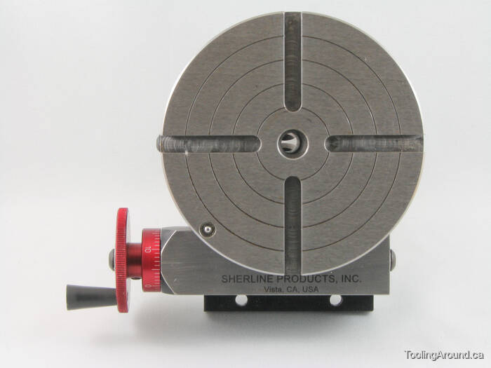
Most small rotary tables have some sort of center hole, sometimes with a cylindrical bore but often with a Morse taper. If the part you"re wanting to center has its own center hole, you might be able to make a plug that fits the rotary table center hole and the part center hole.
The more common way of centering a workpiece on a rotary table requires that you measure the difference between workpiece radii that are 180 degrees apart, and then adjust the workpiece location on the rotary table to split the difference. The most common tool used to make the measurements is a dial gage or dial indicator that must be held stationary; most often the dial gage is anchored to the machine spindle while the rotary table base is clamped to the table.
After you center the work on the rotary table by eye, set a dial indicator up to probe the reference surface. Adjust the indicator holder or move the table so that the dial gage plunger is pressed about half way into its range of travel before zeroing the indicator. Now turn the rotary table top and workpiece (as an assembly) a half turn before reading the dial gage.
Now you want to move the workpiece relative to the rotary table surface until the dial gage reads one-half of the second value. Let"s say your two dial gage readings are A. 0.000 inch, and B. 0.138 inch . . . you want to move the workpiece until the dial gage reads 0.069 inch at BOTH positions A and B.
Next, you need to repeat the measure-rotate 1/2 turn-measure-split the difference process at positions C and D, which must be on a line perpendicular to that connecting A and B.
Since it"s about impossible to move the part on the table exactly the right amount in the right direction, it"s vital that you recheck and readjust A and B after you adjust along C and D . . . and then you"ll need to check and readjust C and D again, and so on and so on. While you"re learning, it"ll seem like you"re chasing your tail, but it is a skill you"ll learn.
To reiterate, the important part is that when adjusting the part on the table you need to rotate the part and table together when you make your measurements, NOT the machine table.
Then later, if you need to center the table under the spindle, you rotate the spindle to measure and move the machine table, which has the rotary table and part bolted to it, to make the adjustment.

You need to insure that the work is centered to the rotary axis of the table and that the rotary table is initially (before you offset by hole circle radius) coaxial with the spindle. If the work is not centered on the rotary table your hole circles will be eccentric (not oval). If the axis of the rotary table is not initially aligned with the axis of the spindle, then your hole circles may be concentric but they are likely to be the wrong radius.
For example, take a piece of turned or ground stock that resembles a round rod with a flange, or anything else you have that is easy to clamp down and sufficiently round and accessible to a dial/dial test indicator. Set an indicator on a magnetic base on table against the part and rotate while watching the needle. Adjust part until it is on center, like indicating in a part on a 4 jaw chuck (A round part in a 4 jaw chuck on rotary table, if you have it, would work well for this step). Now you have a cylinder that is known to be on the axis of rotation of the rotary table. Now, using a dial test indicator in an indicol holder, a dial test indicator chucked in a collet, or a coaxial indicator, keep the rotary table stationary while rotating the center and adjust X and Y until the part is centered. Remove your temporary part. If your rotary table has any apparently round concentric surface that might be suitable for future alignment, test it now to see if it is actually concentric.
You could use the ID hole of the workpiece instead of a separate part for alignment, if it is a good quality reamed hole or, if not checking alignment of the rotary table for furture use, if it is a good enough hole for this application. However, errors in a dividing plate will propagate to other projects made with the dividing plate so you want it to be good. For less critical projects, just use a dial test indicator or coax indicator in the spindle, rotate the rotary table and adjust part center then rotate the spindle and adjust spindle center.
As suggested previously, you can mill the ID and OD of the part in the same setup thereby ensuring that these features are concentric with the same axis that the holes are and not need things aligned properly.

If it"s something that already has holes in it, I usually just whip up a fixture plate for it. Sweep in the head as good as you can get it. Center the rotary table. Make sure it is at 0 degrees. Drill a couple of holes in a piece of scrap aluminum and bolt it to the rotary table. Face your fixture and drill and tap as necessary for your mounting holes. Then machine away on your part. Since you machined everything in situ, then you should be spot on.

The answer depends on the length of the piece. For short-length pieces, you can get by without a tailstock. However, a tailstock for long, slender pieces — such as a rifle barrel — a tailstock is vital to ensure accurate machining without distortion or chatter. Read more
The center of the tailstock is aligned with the center of the spindle if it comes from the factory. If the tailstock is added to a rotary table, the center height of the tailstock is matched to the center height of the rotary table. If you want to check the alignment, you would use an indicator sweep of the tailstock quill. Indicators can be mounted to either the lathe spindle or the rotary table faceplate. Tailstocks can be adjusted side to side, but if the center height is off you will either need to add shims if it is low or remove material if it is high.
There are manual, hydraulic, pneumatic tailstocks, and there are tailstocks with built in live centers. In the case of rotary tables, you can also get a heavy duty tailstock which looks more like a another rotary table to support heavy parts.
There are dead centers and live centers. Dead centers that do not turn are almost always used on manual machine tools or rotary table tailstocks. Live centers, with built in bearings, are commonly used on CNC machines and where higher RPMs are required.
Years ago, before I learned CNC, I owned a Phase II 8″ horizontal/vertical rotary table that I purchased from Kap Pullen’s Getmachinetools.com store. He has them at a good price, BTW, and he’s a darned nice fellow to deal with as well as being a frequent HSM contributor. Anyway, its a nice little table, but I hadn’t done a whole lot with it for quite a while after purchasing it. As is so often the case, one day, a project landed on my doorstep and I was glad to have it.
Before I could get started, however, I had to make some accessories for it. Basically, I needed some T-Nuts to fit the table, as well as a little fixture that makes it easy to hold a plate up off the table through a hole in the center so you can machine it. The latter, what I call a “plate machining fixture”, was inspired by something similar I saw the Widgitmaster of CNCZone fame using to make Dremel clamps for his mini-router:
The Plate Maching Fixture and 3 Homemade T-Nuts. T-Nuts are easy to make: square a block to the proper dimensions, mill the side reliefs, drill, and tap. These are much smaller than the mill’s Bridgeport standard T-slots, so I made them myself and I’m using 1/4-20 bolts with them. They’re made of mild steel.
I turned the round spigot using the 4-jaw on the lathe. I’m making the fixture out of MIC-6 aluminum plate, which is pre-ground very flat on the sides. This is a 5 inch by 3 inch piece. I’ve clamped it to the rotab using my T-nuts and the regular mill clamps and step blocks. It is sitting on parallels to make sure I don’t cut into the table. You can also see how I’ve clamped the rotary table to the mill table using a big cast iron V-block I have. You can never have to many blocks with precision faces hanging around!
Having a 4-jaw chuck on your rotary table is mighty handy! Because it’s a 4-jaw, you can dial in the workpiece by adjusting the jaws until it is perfectly concentric with the table’s axis of rotation. The best way is to make an adapter plate that attaches to the back of the chuck in the same way that your lathe does so you can exchange lathe tooling with the rotab. Here is an example:
For the example, the chuck is threaded onto the adaptor plate, and then the holes in the adapter plate’s flange are used to bolt down to T-nuts on the table.
In my case, I bought a 4-jaw from Shars brand new, and simply drilled some through-holes in the chuck to mount to the table directly without an adapter plate:
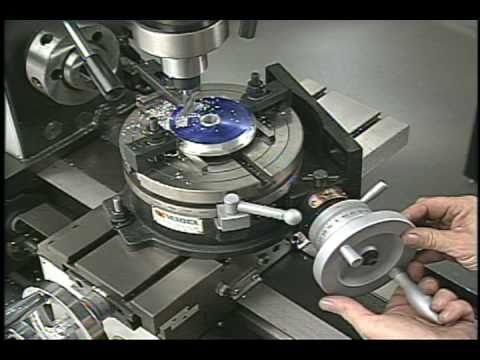
First, you want to make sure your part is properly centered on the table. To do that, I clamp the table down on the mill table (no special place is needed), put my Indicol indicator holder on the mill spindle, and find some round feature on the part to indicate on. For example, on the plate milling fixture above, indicate on the round boss, or on the center hole. Spin the table and bump the part in until spinning the table doesn’t move the indicator.
Second, locate the center of rotation directly under the mill spindle. You can simply use the X and Y table handwheels to do this. Use that Indicol to indicate off of a circular feature you want centered under the spindle. Turn the indicol around on the spindle and adjust the handwheels until the indicator stays put relative to the spindle position. A Blake Coaxial indicator will make this last even simpler.
When you’re rounding partially by cranking a part around on the rotary table, it’s really easy to go a little too far and screw things up. The answer is to drill the end points to make the exact stopping point on the rotab a lot less sensitive:
Centering with a Blake indicator is really fast, but what if you don’t have a Blake, or worse, what if your mill is too small to accomodate one? Here is a nice solution I found on a German site. This fellow has made an ER collect fixture for his rotary table, and has taken care that when installed on the table, the axis of the collet is aligned with the table’s axis. He can then place a dowel or other straight pin in the collet and line up until it will go into a similarly sized collet on the spindle. Nice trick! It’s similar to how Widgitmaster showed me to align a drill chuck on a QCTP to the lathe centerline with a dowel pin held in the lathe chuck.

Shars Tool offers a wide selection of horizontal & vertical rotary machining tables, tailstock, and rotary table with 3 jaw scroll chuck. Whether machining large or small workpieces, Shars has the machining table and dividing plates for your application. Place your order today!

The mill table is raised, and lowered, to measure any difference between "top" and "bottom". Variances are eliminated with shim stock placed under, either the leading edge of the table, or the trailing edge. Idea is to tilt the table in the direction you need it to go. I prefer using the knee crank with the indicator attached to the mill head. I don"t feel that the quill is accurate enough to really get a good measurement. Remember to lock the knee at bottom, and top, of travel. This eliminates any error.
Chuck a reasonably accurate piece of round stock, and see how it trams out over its length. I like doing this because the workpiece is gonna be clamped in the chuck, and I want to see just how much error the chuck is introducing into the setup. This is a comparative test, not something you want to swear by, unless the results are absolutely out of whack. You"re just verifying your original setup that ya did with the indicator.
Why use the chuck, instead of the taper in the rotary table? Your work attaches to your chuck, not the ground taper in the rotary table. Chucks, and chuck mounts, have error. You want to take that error into account when you tram. The world isn"t perfect, and ya gotta do yer best to iron out the humps. AND...……….remember...…….your workpiece is mounted in the chuck, not the rotary table center. It"s the work you need to run true, not an imaginary axis.

Rotary tables can also be equipped with a chuck for workpiece clamping fixtures. These are attached to the set-up table with a flange. Three-jaw chucks are ideal for round or regularly shaped three- and six-sided workpieces. The workpiece is always held centered, because the jaws are operated by a scroll chuck.Centered clamping

Lagun’s BM RT is a bed type mill with C-Axis rotation and equipped with a rotary table. With a compact and robust design, this milling machine is ideal for machining bulky workpieces on all 5 sides.
Lagun’s BM RT mill is built with a modular configuration, which means all models in this spectacular line have interchangeable slides, rams and columns. This design method endows each machine with enhanced rigidity, precision and ergonomic working comfort for the operator.
Additionally the sturdy, oversized mill bed comes with reinforced ribbing, fortifying its stability during heavy milling. The hardy table, measuring at 63” x 47” (1600mm x 1200mm), column, slide and ram systems have been studied and as a result designed with roller/shoes that exceed the manufacturing requirements. Designed to be as close to the column as possible, the mills ram placement ensures a sturdy column-slide-ram assembly. This results in a rigid and light slide for vertical movement. To correct any ram deflection during cross movement they come equipped with special wedges.

For a shop that’s looking to boost its vertical machining center capabilities, the addition of a rotary table can be a cost effective way to take productivity to new levels. One company—both a supplier of parts for bottling, automotive and other production processes and a prototype design services firm—found itself with an immediate need for fourth-axis capabilities to fulfill production for a contract it had been awarded.
“We were in desperate need of a rotary table to meet the production demands,” says Don Borman, co-founder of Borman Enterprises (Cleveland, Ohio). But he also saw another important reason to add the rotary table to the company’s equipment lineup. “The bigger part of our business is the manufacturing end, but that gives us the opportunity to house a training center that’s very functional,” he says. The rotary table was also to become a staple in the process of training the skilled CNC programmers, operators and setup people the company needed, allowing them to see fourth-axis machining at work.
In December 2009, Mr. Borman decided it was time to add fourth-axis capabilities. The company ordered a new vertical machining center with a rotary table so it could bring its fourth-axis work in-house and the training center would be able to incorporate fourth-axis machining into the curriculum. About the same time, the company landed a contract for fourth-axis work, but soon discovered the VMC on order wasn’t going to have the table.
“I found out 2 days before the machine was due here that it wasn’t going to have the fourth axis. That was part of the purchase of the VMC—the table.” That’s when he called CNC Indexing (Wakeman, Ohio).
“I was panicking because the machine had just been installed, and I had the job and material, but I couldn’t do the job because I didn’t have the rotary table,” Mr. Borman says. He checked his options through a distributor. Everyone he contacted said it would take 3 months to get the rotary table he needed. He checked into used equipment. No luck. Finally, his wife found CNC Indexing online.
Mr. Borman says, “What other people told me couldn’t be done (interfacing the controls), Jamie Schwarz at CNC Indexing was positive they could do. And they did it.”
He continues, “Unfortunately, we lost that job because I couldn’t get the rotary table that the machine tool distributor had promised me. Had I known earlier about the missing table, I know CNC Indexing would have been able to have it installed in time. They had the tables in stock, and they filled the void.”
Adding a rotary table (fourth axis) or a tilt table (fourth/fifth axes) to a three-axis machine gives a shop the ability to produce multiple face workpieces more easily and quickly. It also provides more flexibility on the type of work that can be produced. A rotary table opens the door for simultaneous rotating and milling of a workpiece, which is needed to perform complex contours and spirals. The most common reason for and the most obvious advantage of adding a rotary table is the ability to access odd angles (down to 0.001 degree) without designing complicated fixturing. Other not so obvious advantages make the rotary table a good choice for many applications:
Higher part accuracy. The more a workpiece is unclamped, rotated and clamped manually in a fixture to access other faces, the greater the buildup of tolerances. A rotary table allows multiple faces to be accessed without moving the workpiece out of a fixture, thus producing features on a part as accurate to each other as the capabilities of the machine and rotary table. This accuracy results in less scrap and higher profits.
Part production time reduction. By adding a rotary table, the cycle time per part is reduced because multiple operations are performed in one clamping. The machine does not need to be stopped so the part can be turned in the fixture. No time is wasted if the operator isn’t standing at the machine to manually rotate the part.
If the same tool is required on multiple faces of the workpiece, it is possible to do so in one tool change. In most cases, it is quicker to rotate the workpiece with the rotary table than to change tools. This reduces the amount of time required for changing tools over the workpiece’s entire production cycle. It may only be seconds, but added up over shifts, weeks, months and years, those seconds turn into hours of saved time. This time savings allows for more parts to be produced or for additional machine time for other work.
Labor savings. Adding a rotary table allows the workpiece to be in production, untouched, for longer periods of time. The operator, then, has time to walk away from the machine and perform other important jobs within the shop. Fewer employees are needed to produce the same amount of output, saving money for the company.
Non-dedicated machine time. The machining center does not have to be dedicated to rotary table work. In the majority of cases, a rotary table will be mounted to the right side of the machine table. The rotary table footprint is such that it leaves the majority of the machine table free to be used for other non-rotary table work. It also allows the machine to be set up for multiple jobs at the same time.
“We put in a proposal at a plant closing to re-train some of the skilled machinists in the CNC area,” says Tim Duffy, CITC director. “We got the project, which started everything. Don got the certification and got the ball rolling.”
By 1993, Borman Enterprises was certified by the State Board of Career Colleges and Schools. The training services were split off from the company to form the CITC. Classes focus on hands-on training, providing students and graduates access to new CNC machine tools and CAD/CAM systems, as well as quality control equipment and tooling.
“When fourth-axis machining comes up in the classroom, we take the students right out to show a live presentation. It’s live—the chips are flying,” Mr. Borman says. “The instructor brings them up to the working environment to go over the slant bed design of the lathe, or he’ll go over to the rotary table and show them, ‘Here’s the fourth axis, and here’s how you machine with it.’
“These are working machines. That’s really the niche of our training. The problem with other types of training—and I’m all in favor of any kind of education someone can get—is that once the students move on and find themselves in a machine shop environment, they might draw a blank. Suddenly, chips are flying, there’s noise, and they draw a blank. We teach in that environment. The class is working at one machine, and there’s one next to it that is making a part. We’re simulating a working environment. We provide timely and productive training that’s real.”
When it was originally installed, the Golden Sun 10-inch rotary table was set up as a typical fourth axis at a right angle for drilling 30 holes on nozzles designed and made by Borman for a large bottling customer.
The company now has the rotary table laid down on a sine bar at a 20-degree angle, which presents the nozzle at a 20-degree angle, and Borman compounds it another 14 degrees. Currently it is not cutting chips, but it’s set up for the next batch of nozzles. Meanwhile, the company has a vise on the other end of the machine table, which allows conventional VMC work.
“Being a job shop, we have to be versatile,” Mr. Borman says. “When this one account wants samples, they need them now. We have to have the setup, which takes 3 hours, ready to go.”
CNC Indexing’s Jamie Schwarz says the compact design of the Golden Sun table helps in that regard. “It’s very easy to work with as far as space. It doesn’t take up the whole machining envelope.” That leaves ample open table space for maneuverability and flexible use.
Mr. Borman says he’s had a good track record with Golden Sun. And the new rotary table did not disappoint. “It’s just a user-oriented, price competitive table. That’s what I look at more than anything. I don’t think we’ve ever had a maintenance issue on the 10-inch table in 3 years. It keeps running and running.” The company has since gained still more capacity by purchasing a new 12.5-inch rotary table.
With 16 CNCs (two dedicated to training) and 20 operators during two shifts, students are scheduled on any machines with open time. “We schedule the students just like we would a job. Right now, both fourth-axis machines are not cutting chips, which is unusual,” Mr. Borman says. “Next week at this time, both will be busy, and we could almost use another one. If it weren’t for our added capacity, we would probably have had to turn down training folks.”
But most of the students aren’t quite ready for fourth-axis work. To date, learning fourth-axis methods is more lecture than hands-on. It can be incorporated into a class project during the standard 17-week program, but Mr. Borman says they can only cover so much.
That’s no surprise to Mr. Schwarz, who’s been in the CNC machining business in one aspect or another since 1994. Setting up machining centers with machine tool accessories throughout the U.S. and training machine operators to use them brings him in contact with a lot of machinists. The skill levels, Mr. Schwarz says, are all over the board.
“That’s one of the reasons we were excited about working with Borman and CITC. A lot of companies out there really need machinists with higher skills. So, there are a lot of opportunities for machinists with the skills this training center can give them. We like being involved in that,” he says.
Mr. Borman agrees. “We might have one or two students out of a class of ten or 12 who can really appreciate what the fourth axis can do. For the others, it may be a little more complex than the intent of this program. But it’s available to them if they’re ready to progress beyond three axes.”
“We’ll talk to the general public as well as 30-year machinists who have never touched CNC in their lives and just got laid off,” Mr. Duffy says. “We can take a guy like that and turn him around in 4 months and get him a good job.”
Although the center focuses on hands-on training with machine tools, Mr. Borman, Mr. Duffy and Mr. Schwarz feel the engineering aspects are critical for experienced machinists. “We wanted to bring the engineering stage into this class, too, so it would appeal to the entry-level person but also interest a seasoned machinist looking to round out his programming capabilities,” Mr. Borman says.
“Regardless of what an individual brings us, we can raise their level, no matter what their starting point is,” Mr. Duffy adds. “Even within a given class of 12 to 14 students, we can identify their strengths and weaknesses and appeal to everyone. We don’t just take a cookie-cutter approach to every class. We have an obligation to every student to ensure they graduate from the program and get a good job.”
Students who are completely new to machining are given an entrance exam to assess skills with fractions, decimals and percentages. If those abilities are there, he says, the center can train them. The center also provides on-site training for area companies. Classes can be as simple as a 20-hour shop math class or blueprint reading to customized instruction like the 45-hour, highly specialized mill training class for Swagelok.
Borman Enterprises often hires students from CITC. In 2007, it opened another instructional center, the Akron CNC Training Center, conducting classes and lab projects at S.C. Manufacturing. In 2010, CITC began the first and only CNC Swiss machine operator training program in Ohio.
“We were happy to take that call from Borman for a lot of reasons,” Mr. Schwarz says of his first conversation with Mr. Borman about the rotary table. “But working with really knowledgeable engineers like Don and Tim, and seeing what they’re accomplishing with these training centers, it’s a great thing. It’s great for the industry, it’s great for this region, and it’s great for the guys in training who move on to good jobs.”
The rapidly increasing demand for high-value threaded parts with exceptionally high length-to-diameter ratios has created a lot of interest in thread whirling technology among American shops and manufacturers.


 8613371530291