
centering workpiece on rotary table brands

then, to centre the workpiece itself, you first decide what accuracy level of centring you need.....just using a pointy mill wiggler in the spindle and aligning it with scribed lines on the workpiece can get you within .005 if you"re careful.
if you need to be closer, take a step back in history....."button up" the job with a toolmakers button......drill and tap for the button in the workpiece"s approx centre, snug up the button, adjust the button to the exact desired relationship with whatever surface or other feature of the workpiece defines your centre, and tighten up the button.
when your workpiece is placed on the rotary table, sweep the button with an indicator in the spindle, adjust position til your indicator zeroes out, and you"ll have it centred within the possible accuracy of the setup.
Mounts directly to a rotary table, Fixture Pro® Riser or any QLS Grid. Reduces distortion of parts like standard vises. Requires very little material (0.060” or less) to clamp. By cutting a 10º angle ...
Mounts directly to a rotary table, Fixture Pro® Riser or any QLS Grid. Reduces distortion of parts like standard vises. Requires very little material (0.060” ...
... gripping equipment. Detailed documentation is provided on request.These vises are exclusively intended for use as a static locking unit (mounting on CNC rotary tables, with rotating tools); ...
... gripping equipment. Detailed documentation is provided on request. These vises are exclusively intended for use as a static locking unit (mounting on CNC rotary tables, with rotating ...
High pressure ARNOLD TWIN vices are capable of clamping two pieces simultaneously.- Accuracy of 0.01 mm in clamping repeatability.- Suitable for working in horizontal and vertical machining centres.- Grinding of all ...
With DirectIndustry you can: Find the product, subcontractor or service provider you need | Find a nearby distributor or reseller| Contact the manufacturer to get a quote or a price | Examine product characteristics and technical specifications for major brands | View PDF catalogues and other online documentation

A CNC rotary table is the precision positioning accessory that can provide a reliable 4th axis or even 5th axis for modern machining centers. Utilizing a computer-controlled rotary table can turn the original 3-axis machine tools into 5-axis CNC machines, expanding the accuracy as well as decreasing the costs while performing complex machining operations at one time.
A CNC rotary table is the precision positioning accessory that can provide reliable 4 or even 5 axis cutting operation capabilities for modern machining centers. Utilizing it can turn the original 3-axis machine tools into 5-axis CNC machines, expanding the accuracy as well as decreasing the costs while performing complex machining operations.
Rotary tables typically have rigid frames and coatings, and also excellent torque capacity, which makes the small device flexible and effective for a wide variety of turning, milling, drilling, and more metalworking operations. The easy setup and seamless interface allow the operators to easily add the rotary table to fit their 4-axis or 5-axis applications. .
The working principle is similar to the basic rotary tables, which is to support the workpiece by accurately rotating the workpieces on the axis in order to locate the parts for high precision tooling. Under rapid rotation, which is driven by CNC instructions, the cutting tools of larger machine tools or machining centers can remove the material and add the feature to the products at exact intervals. On rotary tables, there are vertical and horizontal axes for various tools to perform these high-performance metalworks. To enhance the accuracy and flexibility, there are models that employ additional dividing plates and come with additonal material handling mechanisms and features.
Since 4-axis and 5-axis machining is increasingly popular today, adding the CNC rotary table as the 4th axis is an ideal solution to easily open up more complex machining options at a lower cost. Due to the arrangement, they are widely also called the 4th or 5th axis or tilt rotary. The 4th axis, which is the rotational operational direction, is added to the original three linear axes which are known as X-axis, Y-axis, Z-axis. In some cases, there are two rotational axes add to the original 3-axis machining center, achieving utmost accuracy as well as effective multiple face cutting to reach the difficult area on the surface. Rotary tables are usually mounted parallel to the ground or the bed, with the platter rotating around the vertical axis, for example with the most common vertical milling machine combination. Sometimes the machining application requires an alternative setup with the table mountet on its end so that it rotates around the horizontlal axis. Often, a tailstock is used in this configuration. Virtually all models today come with a clamping kit to mount it onto the bed of your machine tool.
The function of the high precision rotary table is also to rotate the workpiece so the cutting tool can create the contour we desired out of the workpiece. However, a rotary table with higher precision has the ability to achieve great accuracy just as its name implies. There is also a major misconception between the resolution and the accuracy.
A common example is that if a digital readout displays to four decimal places, then the high precision rotary table must also be capable of achieving the accuracy to that same value. Even though for higher accuracy to be achieved, the resolution has to also be high, but there is no guarantee that the accuracy is going to be high. The accuracy is the concept which is the difference between the actual position and the position measured by a reference measurement device. The feedback mechanism such as the rotary encoder, and the drive mechanism can influence the accuracy of the advanced rotary table.
A CNC rotary table can provide great rigidity for stable machining operations. It consists of the worktable where the metal parts are held, the rigid bearing that withstands the forces and loads during the rotation, the solid base which is used for attaching the rotary table to the machining center or other equipment, the motor, and the CNC system.
The worktable is the tooling surface where the workpieces are machined after accurate positioning. The worm gearing is the core mechanism of the table, which mesh with the steel worm which is submerged in the lubricants. Both the rigid bearings and the worm gears have large diameters. Excellent concentricity is the key to smooth operation, durability, and most importantly, accuracy. Driven by a computer and electric motor, the worktable can position the materials at exact intervals. For more flexible or critical operations, dividing plates can be added to this component.
A CNC system regulates the simultaneous 4-axis motion of the rotary table. The instructions are programmed and transmitted via CAD software, reducing the time for adjustment and monitoring by human workers.
The type and size of the electric motors utilized in can define the router accuracy as well as the efficiency of the device. Servo motor and stepper motor are two typical types that can be divided into more subtypes. The servo motor uses a closed looping variable circuit, the circuit will constantly run to keep the function. The brushes must be replaced every 2000 hours of operation in the servo motor. Compared to stepper motors, servo motors are more efficient in power consumption. On the other hand, the stepper motor has a simpler setup which are the wires that are attached to the driver. The bearing of the stepper motor is the only wearing component. However, the stepper motor consumes a great amount of energy.
There are currently several different types and models available in the industries. Each of them possess its own traits and abilities. Let us take a look at the most common ones other than standard three axis tables
The 4 axis CNC rotary table will process the workpieces by holding them in the same position while the cutting tool performs along the XYZ plane to trim away the unwanted material. In general, a 4 axis model is very versatile equipment that can be used for several different industrial processes such as engraving curved surfaces, continuous cutting, and intermittent cutting. Besides, people can also add other devices such as cam machining, blade machining, and helical grooves to the 4 axes rotary table. Such a feature is simply impossible to achieve with the machining center which has only 3 axes.
Besides the 4 axis ones, there are also 5 axis models. They have the ability to allow the workpiece to be processed automatically from five sides at one time. people usually utilized the 5 axes rotary table in the industries such as the automobile, the aerospace, and the boating industries. The reason that the 5 axes rotary table is commonly used in heavy industries is that the 5 axis machining is an important technique to be used when the components need better intricacy and quick precision. All of these have more than three axes are called the multi-axis rotary table.
The installation method of the precision rotary table can be horizontal, vertical or inverted. When installed horizontally, the workbench surface is in a flat, vertical and horizontal position. When installed vertically, a rotary table is installed so that the surface of it can run up and down. In the reverse layout, itcan be rotated upside down in a horizontal position. The location of the drive of the rotary table can depend on the mount. The drive can be placed on the back, below, on the top or on the side.
When mounted horizontally, the spinning table top drive is positioned above the table floor. When the rotary table is horizontally placed, the side-mounted drive is located on the edge of the table board. The driving mechanism of the rotary table may be manual, electrical, pneumatic, hydraulic or non-driven. For manual revolving workbenches, release the workbenches and manually spin the workbenches with the crank.
Workpieces are gathered and machined through PC and fully programmed instructions. The 5-axis simultaneous operations will be measurably more reliable than products machined via different technologies. Also, the setup is simple and provides an indistinguishable process in every production cycle, the consistency of the quality of the metal products can be ensured under critical control and precision cutting.
Since the metalwork is driven by software, the preferred frameworks can be programmed and adapted by the rotary table. Saving both the cost and the room makes themis the ideal solution for potential users who don’t want to install larger equipment and new machines which may take up a great room for a wide variety of machining applications.
Another benefit is the utmost movements can be completed precisiely and faster. There are more favorable positions, operation angles as well as accessible machining that can be achieved through the technology. The complex operations are suitable for blade, helical grooves production, and other applications required to add complex features or require critical inspection in machining processes like the manufacturing of aerospace, automotive parts, and scientific equipment.
Addding a rotational table saves time because the extra finishing jobs or other sub-operations can also be performed at one time in the machining center.
A rotary table can be used in many applications including manufacturing, inspection, and assembly. Indicators are used, for example, for assembly, manufacturing, and bottling equipment. They typically use a single item in workspaces or move relatively small layouts of items around stations for sequential work or assembly.
In automated assembly machines, the rotary tables implementation is widespread, and choosing the right mechanism is important for both improving efficiency and reducing the cost of this vital component. This guide discusses two common devices for rotating indexing and offers guidance on the right range. There are several ways to get mass mobilization when it comes to the development of rotary indexing tables. Regardless of whether the load or load in centuries of thousands of kgm2 is incredibly light. When choosing a robust rotary index solution that will match or meet your standards, there are several factors to take into account when spinning, elevating, or pushing.
When determining the influencing factors on the postitioning accuracy, the first thing to look at is the mechanical properties of the table itself. A rotary table contains six degrees of freedom. Each of these movements increases the total risk of positioning errors. Usually, a rotary table is driven by a worm gear, which is connected to the motor through a rotary encoder on the back. The position of the table can be determined by the number of pulses transmitted from the encoder to the control device.
The four main sources of error due to the semi-closed position loop are geometric errors, thermal deformation, elasticity, and wear. The sum of these errors is called angular positioning error. To greatly reduce the angular positioning error, the ideal position for installing the angle encoder is on the rotating shaft under test. The angle encoder is installed under the rotary table, and the rotary encoder is installed under the rear motor, the position loop is now considered a closed-loop system.
Precision is a relative term. About a quarter of an inch is great and will meet the accuracy of its application. Others, for example, require micron-level accuracy in measuring and indexing devices. Then, some applications fall within these extreme ranges.
The misunderstanding is that you may have used an inaccurate indexing device and made it accurate by introducing a pin or wedge locking device. These devices increase the complexity and cycle time of use, and when they are used together with a high-precision positioning device, they may cause damage and reduce accuracy.
In the actual test, by selecting specific components, motion index drive, servo rotary indexer, the measurement accuracy is as high as 5-6 microns. These are not the results approved by Motion Index Drives, but the results of customer certification. When starting and stopping large amounts of data, it is important to know how fast it takes to stop the application with large amounts of data.
In a less rigid environment or the presence of higher recoil, a faster start and stop will bring many control problems. When moving masses (whether rotating mass or linear mass), starting and stopping in a system with a backlash of several arc minutes will cause a lot of back and forth movement in the gear system. The result is a force that is difficult or even impossible to calculate. In addition, when the gear head is used in rotating applications, the farther the mass is from the center of rotation, the greater the backlash. In applications with very slow deceleration times, recoil may not be a problem.
Backlash in the positioning process is a big issue – when it comes to the beginning and stopping volumes, it"s crucial to know how quickly you need to avoid the mass of your rotary indexing table applications. In a less rigid system or where there is an increased backlash, quicker start-ups and stops can cause a lot of control issues. When shifting a mass, whether rotary or linear, starting and stopping in a system with several minutes of backlash arc will create a lot of back-and-forth motion within the gearing system. The effect is a power that can be difficult and probably hard to quantify. In comparison, as the gear head is used for rotational applications, the more the mass is from the axis of rotation, the further the backlash is magnified.
The backlash may not be a concern in systems where deceleration times are incredibly long. In the case of cam indexers, there is " Zero Backlash." The cam indexer and rotary table dynamics give an incredibly rigid, highly regulated framework. A modern cam indexer system is capable of withstanding short cycle times with stop times in milliseconds.
So you want to get the smart manufacturing going but are not sure of what to look for in rotary tables. The information provided in this section may be able to help. The primary factor is to determine the mass snapshot of inactivity. This is often overlooked when measuring a rotary table for the machine.
Another significant factor is the size of the workpiece being rotated, including how big it is and how substantial it is. You want your rotary tables to be large enough to handle enormous pieces. This is where tilling rotary tables may become handy so that the pieces can be handled without causing interior harm. They allow the quickening and decelerating of machining at appropriate rates.
The last factor is accuracy, the applications for which, for instance, pivoting a gigantic part to allow welding highlights on it where the individual stop positions can be genuinely free. On an additional note, when choosing direct drive rotary tables, factors that you should consider when selecting a rotary table for your CNC machinery include accuracy, backlash, mass moment of inertia, acceleration and deceleration, speed, and environment.
Indexing system use is commonly possible in automatic assembly machines and the right process is important for both performance maximization and cost reduction.
Cam indexers are an omnipresent tool used for several decades for rotary indexing tables. They are suitable for applications that often index the same angle and need a high degree of accuracy at a relatively low cost. To place the load, a cam indexer uses a mechanical cam. A math curve is pushed onto the cam and provides incredibly smooth and repeatable movement.
Another popular alternative is a fully programmable rotary index table. A rotary table is advantageous in two different situations. Firstly, a versatile movement pattern is important. An example is if two components are running on one computer, each of which requires different index patterns. For incredibly fast placement accompanied by a long period, another condition that matches the servo pointer is. The need to accelerate the camshaft while the cam indexing mechanism was operating before starting the output movement reduced the on-demand cam indexer. Acceleration of the camshaft is possible, but there is a delay before the movement begins. There are realistic restrictions.
With an indexing table, the output rotates as soon as the servo starts moving. This is not difficult for a continuous cam indexer or a zero-backlash servo indexer, but it can also be difficult for an on-demand cam indexer. For applications with high-speed servo indexing, smooth movements are crucial. A zero-backlash preloaded reducer can achieve this. The ideal alternative for correct positioning with high dynamic response would be the zero-backlash reel drive system.
Application parameters, like a moment of inertia, indexing angle, indexing period, and residence time, are required for each indexer style. The rotary indexing table for the application should also be sized correctly by a reputable manufacturer.

Fig. 4—On this tilting rotary table, one servo controls rotation, another controls tilt. Both servocontrols are slaves to the CNC with RS-232 communication, providing five-axis capability from a standard three-axis CNC.
Fig. 1—Modern rotary tables such as this one from SMW Systems have large, widely spaced spindle bearings, large diameter wormwheels and built-in spindle brakes.
If you want to make parts similar to the complex valve body (upper left), an indexer using M-code, RS-232, or “full fourth axis” control is appropriate. Only positioning and rotary cutting moves are required. The center workpiece is a cam that requires simultaneous rotary and linear moves. You’ll need full four-axis control for such workpieces. If you want to do parts similar to the impeller on the right, the contour cutting will require simultaneous five-axis machining.
Many plant managers and shop owners dream of having the latest horizontal machining center (HMC) with all its features, benefits and sophisticated capability. While typical HMC features such as an automatic pallet changer and a 100+ cutting tool magazine are valuable, perhaps the most valuable characteristic is the HMC’s ability to machine on more than one side of the workpiece due to a built-in indexer or full fourth axis.
On complex workpieces that require machining on surfaces not 90 or 180 degrees from each other, indexing or fourth-axis rotation is almost essential to produce the piece. Even when rectangular workpieces with all surfaces 90 or 180 degrees from each other are put on a tombstone, the HMC’s built-in fourth axis of rotation creates a productivity advantage. This is true even if machining on more than one side of the part is not essential.
Any time you can increase the “run cycle,” do more cutting in one operation and avoid handling the workpiece, productivity goes up. Workpiece accuracy also improves. Unclamping and refixturing a workpiece to present a different surface to the cutting tool is always going to introduce some error.
The high cost of horizontal machining centers compared to the incredible values available today in vertical machining centers puts horizontals out of reach for many shops. Fortunately, today there are several suppliers of quality accessories that allow the VMC shop to equip its verticals with indexers, fourth axes and tombstones. These add-ons really work and give many of the benefits of an HMC at a fraction of the price.
Earlier rotary tables and indexers didn’t have the accuracy, rigidity or control flexibility of today’s models. Many shops that tried using indexers in the past had been disappointed in the performance of the older models and abandoned their use in favor of multiple operations, multiple holding fixtures and multiple handlings of the workpiece. They decided that the manual, multiple-operation process was better than trying to use ineffective early model indexers and rotary tables. Today, the situation is different. Manufacturers now offer units that are very accurate, very rigid and have a variety of control and interface options.
The best indexer and control system for you depend on the work you need to do. As with most things, different designs compromise certain capabilities to gain others. Unless you understand these trade-offs, you are at risk of selecting something other than the best system for your requirements. Let’s see what’s available, review the differing capabilities and discuss the advantages and disadvantages of each design. Once you understand the options, you can evaluate them against your requirements and then consider prices and suppliers.
Of course, such a system does not exist. Add the “lowest price from the supplier that gives the best service and support” component and it probably never will exist.
Terminology in the area of indexers is not standard. Terms such as fourth axis, indexer, rotary table and so on are used interchangeably by different machine tool and accessory companies. So, when selecting and buying, you must ask a few questions before assuming you know what you’re going to get. Also, beware of terms such as “precision,” “high precision,” “accurate,” and “rigid.” Is the “brake torque” specification some absolute break away spec or the torque at which some “unacceptable” amount of rotary deflection occurs? Is the “ten arc seconds” accuracy specification certified every one degree, or is it inspected only every 15 degrees? There are no industry standards for specifications and testing. So ask questions and deal with a supplier in which you have confidence, or buy with a guarantee of performance to make your parts.
We’ll start with the mechanical hardware and discuss the electronic control options later. There are at least three common mechanical indexer/rotary table types.
These tables provide infinite positioning as well as the possibility of rotary cutting. A servomotor controlled directly either by the CNC or by a secondary servocontrol rotates a wormscrew, which drives a wormwheel on the rotary table spindle.
The absolute position accuracy of these systems is a function of the quality (precision and accuracy) of the wormgear set (wormscrew and wormwheel), the accuracy and resolution of the servosystem, and the means of servoposition feedback. Most of these servosystems utilize an encoder to monitor the position of the motor rather than the rotary spindle directly. To eliminate any inaccuracies in the wormgears and servo system, some high-end systems use a glass scale or other encoder directly on the rotary spindle to monitor actual rotary spindle position. Figure 1 (at right) shows a typical wormgear rotary table cross section.
If controlled directly by the machine tool’s CNC, they are most commonly referred to as a “full fourth axis.” A full fourth axis has the advantages of having only one CNC program, no programming required by the operator on the shop floor, minimum chance of a crash due to operator error, and the ability to make simultaneous rotary and X, Y or Z moves to do true helical milling operations as required by some more exotic workpieces.
Claims of position accuracy are often misleading since there are no industry standards. Although some manufacturers test and certify absolute position accuracy every one degree, most do not state exactly what their specification means.For all except those few expensive systems with glass scales directly on the rotary spindle, any accuracy specification is for a new table before it has been subjected to any “crashes,” which are not uncommon. Even seemingly small crashes can damage wormgear sets.
Typical infinite positioning wormgear systems utilize a friction brake to hold position against cutting forces. When cutting forces are applied directly on the rotary spindle centerline, friction brakes are generally adequate for most work. However, when cutting forces are applied to workpieces far off centerline, such as on the edge of a part on a tombstone fixture, the resulting torque on the rotary spindle can cause it to deflect. This result is especially likely when heavy cuts produce high thrust forces.
These indexers offer discrete positioning only. Depending on the number of teeth on the face gear, the minimum increment of index might be 15 degrees, 5 degrees or 1 degree. Whatever the minimum increment, only workpieces with angles representing some multiple of the minimum can possibly be machined.
Face gear mechanisms used in indexers are similar to those most commonly found in the turrets of CNC lathes, which by function must index very accurately and very rigidly to withstand the high cutting forces the lathe turret encounters. Face gear mechanisms generally fall into two categories, the two-piece and the three-piece design. Two-piece designs require the face plate of the indexer to “lift” to disengage the face gears. Three-piece designs maintain the same accuracy and rigidity of a two-piece without the need to “lift” the faceplate. In Figure 2 (at right), note the massive face gear that locks the indexer spindle in position.
Assuming it’s a quality face gear set, absolute position accuracy is superb and is maintained for the life of the indexer almost in spite of any “crashes” that might occur. Units with true absolute angular position accuracy of 5 arc seconds or less are available. These units are ideal for the highest precision work such as line boring half way from one side, then indexing 180 degrees and line boring half way from the other side.
Some face gear systems use a servodrive to achieve approximate position and then rely on the face gear for final accurate positioning. These systems are bi-directional and fast. Any random move can be programmed with one simple command. Some other systems use a pneumatic piston to rotate to the approximate position. Typically, these systems rotate only in one direction. All moves must be equal and may require a pause to utilize more then one M-code signal to achieve position. These work but can be tedious to program, set up and operate. They are more prone to crash due to operator error then servodriven units.
These indexers are becoming a thing of the past. They have all the disadvantages of the pneumatic piston driven incremental face gear indexers. Plus, compared to face gear units, they are neither particularly accurate nor rigid. Index positions are usually limited to 15-degree increments. Position is controlled by a pin in a hole or more often by a dog in a notch on the outside of a ring.
Whether you select an infinite positioning wormgear rotary system or a facegear system as the best mechanical design for your work, your next decision involves how you will control the rotary axis.
With a pneumatic incremental indexer, you probably will have no choice. Your machine’s CNC will control the indexer by communicating with a special indexer control via an M-code.
If you select a system with a servodrive, you have three choices: 1.) direct “full fourth axis” using only the machine’s CNC, 2.) an M-code command from the CNC to a separate rotary control, or 3.) RS-232 communication between the machine’s CNC and a separate rotary control. Each of these choices has advantages and disadvantages.
A single, four-axis CNC is the easiest to use and provides the most control. Four-axis CNC is best for certain kinds of workpieces. Full four-axis control systems are usually ordered for delivery with a new machine. Systems can be retrofitted; however, retrofitting is complicated and expensive. The advantages of a single four-axis control are numerous, and the disadvantages are primarily related to cost.
The single CNC constantly tracks all three linear axes (X,Y,Z) and the rotary axis. This provides the ability to do precise helical cutting with simultaneous rotary and X, Y or Z moves.
While a few machine builders offer a full four-axis control with rotary table for about 10 percent of the base price of the machine, most charge more than 20 percent.
Very few machine builders make it easy to retrofit a full four-axis rotary table. For most builders, retrofitting is a complicated process, and the cost typically exceeds 30 percent of a base machine price.
The motor for the rotary axis must be matched to the servodrive of the CNC. Because cable connections are not standard from one machine builder to another, rotary tables can not generally be used on more than one machine.
Some applications may require the accuracy and rigidity of a face gear system. However, many machine builders don’t offer face gear systems with a full four-axis control, although such systems are feasible.
An M-code actuated system provides a fourth axis of motion by combining a standard three-axis CNC with a rotary table or face gear indexer that has its own separate rotary servocontrol. The rotary program is entered and stored in the separate rotary servocontrol. The CNC communicates with the rotary control via an M-code. When the rotary control receives the M-code signal, it executes the next rotary move stored in its memory, then sends a signal back to the CNC, telling it that the move has been completed.
Typically, the rotary program includes many separate rotary moves. One move might be a simple index to position at full rapid speed. Another might be a slower rotary move to machine a groove or other feature on the workpiece. Figure 3 (at right) shows a typical rotary servocontrol system.
High quality M-code controlled systems are available from several suppliers for a price of about 10 percent of a base machine price. (For example, a 5C rotary system at $6,000; a 6-inch faceplate system at $7,000; a 9-inch system at $10,000; and so on).
Requiring only one M-code, 110V power and an air line for operation, these systems can be retrofitted to almost any CNC machine, typically with less than a day of downtime.
Systems can be moved from one machine to another as long as the next machine can issue M-codes. A shop with multiple machines and multiple rotary systems can select the best system for each job regardless of the machine. For example, a small indexer can be used for small parts to avoid cutting tool interference problems and to minimize indexing times. A big indexer can be used for big parts. A face gear indexer can be used when the maximum in accuracy and rigidity are needed and the work can be accommodated by multiples of 5 degrees of index.
The machine operator needs to enter the rotary program into the rotary servocontrol, or select the right program if it’s already stored in the rotary control’s memory. This takes some time, and there is the chance of an error.
If the machining cycle is ever interrupted in mid-cycle, such as to inspect a workpiece feature or replace a worn cutting tool, the operator must be sure to back up the rotary program and the CNC program to a point that keeps the two programs in sync. This step can be confusing, and any error can result in a “crash,” with a cutting tool coming down to a workpiece rotated to the wrong position.
Although it is possible to perform simultaneous rotary and X, Y or Z moves, they are not recommended. If you have patience and can afford to scrap a few parts, you can use trial and error to find the right rotary speed to match the linear move and determine starting points that match.
Recently developed, RS-232 communication between a three-axis CNC and a rotary servocontrol offers advantages of full four-axis and M-code operation. RS-232 is the commonly used, standard electrical interface for connecting peripheral devices to a computer. Personal computers often use the RS-232 communication protocol to send information to a printer. Another common use for RS-232 communications is connecting a PC to an external modem.
Nearly all CNC units have an RS-232 port, and it is commonly used to exchange CNC programs between a computer system and the CNC. More recently, RS-232 connections have been used by CNCs to communicate with robots and rotary tables. To communicate with the rotary table’s control, a special line of code is inserted into the CNC program. This line of code sends a string of numbers and letters through the RS-232 port to the rotary table control, which translates the string of code into rotary moves.
RS-232 communication between a three-axis CNC and a rotary servocontrol provides much of the best of both worlds of full four-axis and M-code operation. Both the linear and rotary moves are stored in the CNC as part of the workpiece program. When a rotary move is required, the CNC sends the commands for that one move (rotary speed and angle of rotation) through an RS-232 line to the rotary control.
The rotary control executes that one move and sends back a signal to the CNC, indicating that this move has been completed. The CNC then commands its next linear move. The separate rotary servocontrol simply works as a slave to the CNC. The machine operator turns the rotary control on in the morning and does not need to attend to it the rest of the day. Figure 4 (at right) shows a tilting rotary table system utilizing two rotary servocontrols with RS-232, providing five-axis capability from a standard three-axis CNC.
Crashes are nearly as unlikely as with a full four-axis control. The correct rotary program is always selected because it is part of the total workpiece program stored in the machine’s CNC. Note: Rotary moves should be programmed in “absolute position” so that if the machining cycle is interrupted, the operator can back up the CNC program to just in front of a rotary move, then safely resume the program.
Retrofitting is easy provided the machine’s CNC has an RS-232 port and appropriate communication software, which may already reside in the CNC or be available from the machine builder.
With RS-232, two rotary controls can be operated by most three-axis CNCs with only one RS-232 port. Five-axis capability with a tilting rotary table setup can be retrofitted to a three-axis machine for about $25,000 (a new, full five-axis VMC option is typically priced at $95,000).
Both the work you need to do and the machines you own or intend to purchase will influence what you select for a rotary axis. These guidelines summarize what you should consider.
When buying a new machine, get prices on everything the builder offers, no matter what kind of workpieces you’ll be machining. If the builder offers a full four-axis system with a high-quality, infinite-positioning rotary table at a price of about 10 percent off the base machine, this system will probably be your best choice.
If your workpieces can take advantage of the accuracy and rigidity of a face-gear system, and you can live with the 5-degree minimum increment, a face gear system controlled by RS-232 or M-code is a good choice. A few builders offer a face gear system with true four-axis control.
If you’re doing a variety of work that requires simultaneous rotary and linear helical moves, you’ll probably want a true four-axis system regardless of the cost. However, you should consider a more economically priced RS-232 or M-code system when you are retrofitting an existing machine and have only a couple of jobs requiring these moves, especially if these jobs are long run and you can afford some extra programming and setup time. These systems are worth considering if you simply can’t afford the price of a true fourth axis.
If you’re retrofitting existing machines, especially if you have several and want to do rotary work on more then one of them, check with the builder on the cost of upgrading to full four axis. You may conclude that the cost and flexibility advantages of RS-232 or M-code will make one of them the best choice.
Adding a rotary axis to a VMC is worthwhile whether you want to do full four-axis simultaneous machining of exotic workpieces, simple indexing of parts that need machining on surfaces not at 90 degrees from each other, or tombstone processing of rectangular parts that benefit from a longer unmanned machining cycle. Today, many good options exist. If you’re buying a new machine, have the builder quote the optional systems it offers. If you’re going to retrofit an existing machine, contact either the original supplier or the companies that offer complete indexer and rotary table systems. Retrofitting is highly affordable. (Systems from SMW Systems, for example, generally cost a little over $1,000 per inch of faceplate diameter, including installation and training.) MMS
Mitee-Bite Products’ fixtures demonstrated their powerful clamping support in a project with Akron Gear & Engineering to vertically hold a 1-ton ring during machining.

Our product range includes single and multiple axes, tilt/rotating tables, and indexing and high-speed spindles. Additionally, we offer customized solution tables for customer requests or OEM projects.
Customer satisfaction is our highest priority. Due to a high degree of vertical integration, our customers have one point-of-contact and the guarantee that all components are manufactured and assembled to your specifications.
Even for EDM machines that have been in use for decades, we will work with you to determine the ideal rotary indexing table and/or rotating/indexing spindle solution.
Our state-of-the-art rotary indexing tables and customizable reference and clamping systems provide endless application possibilities and highly efficient solutions.
Customer satisfaction is our top priority. You specify the task and together we’ll find the optimal solution for your production challenges and products.

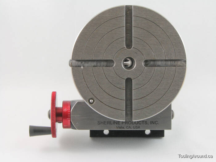
When using a rotary table on a mill, whether to mill an arc or drill holes in some circular pattern, there are two things that must be done to set up the workpiece. First, the workpiece must be centred on the rotary table. Second, the rotary table must be centred under the spindle. Then the mill table can be moved some appropriate distance and you can start cutting.
You could centre the table under the spindle first, by indicating off the hole in the centre of the table. Then you could mount the workpiece on the table and indicate off the workpiece. There are two problems with this approach. First, you are assuming that the hole in the table is true and centred. That may or may not be true. Second, this approach risks a sort of accumulation of errors, as you"re measuring from two different features (the rotary table"s hole and some feature on the workpiece). My suggestion is to centre the workpiece on the rotary table first, and then centre the rotary table under the spindle.
As shown in this photo, a DTI has been positioned with its tip against the inside of a hole in the workpiece. The DTI is held in the mill spindle, but that"s just for convenience. (When I do this, I put a little wooden wedge between the spindle pulley and the headstock, to make sure the indicator remains stationary.) It could as easily be held on a test stand. Indeed, the measurement doesn"t have to be done on the mill at all.
To centre the workpiece on the rotary table, spin the rotary table and watch for deflection of the indicator pointer. Adjust the chuck jaws as required, until the needle no longer deflects.
After the workpiece is centred on the rotary table, you now turn the spindle by hand, so the DTI tip sweeps the inside of the hole. Adjust the position of the mill table as required until no needle deflection is noted.
Again in this photo, a DTI is measuring from the inside of a hole. As in the previous illustration, the rotary table is spun and the workpiece"s position on the rotary table is adjusted until the DTI shows no deflection.
After the workpiece is centred on the rotary table, you now turn the spindle so the DTI tip sweeps the inside of the hole. Adjust the position of the mill table as required until no needle deflection is noted.
You can, of course, use the pointed end of a centre finder to position over a point on the workpiece. When centring the table under the spindle, if you are indicating off a larger hole or other curved feature, you may need to mount the indicator on a short arm, so you can sweep a large enough radius.
Here is what I like to use as a test indicator holder. It can allow you to indicate in something without removing the tool. They have several options for in spindle or spindle nose clamp styles. eBay does have some cheaper import version that work ok, but once you have use the Indicol quality, there is a big difference. You will need to buy the test indicator as a seperate item. There are a lot on the market. I have had my B&S(brown and Sharp) "Best Test" indicator for almost 30 years and one repair. Reasonably rugged and very reliable. Sticky indicators like some imports do you no good. If the needle pointer does not move, it is inviting a false sense of security.
The whole premise is to use the spindle bearings to sweep an indicator around the surface you wish to align it to. It is much easier in concert with a DRO, but dials will get you there too.
As long as you do not move the table, you could indicate the part in by knocking it around until it sets in the same location. You could also spin the table itself and knock the part around to find its true center on the rotation of the table bearings. Some of the cheaper import rotary tables may not have the spindle bore as reliably on center as what they will rotate on their shaft.
The same indicator setup can check for spindle tram also. This will need to be checked periodically anyways to verify the spindle is perpendicular to the table surface. If the head is tilted and you indicate in a feature. If the point that it is indicated in at changes in height, so to will the location of the features you intend to machine in relation to that reference. The longer the tool bit is away from the indicated origin, the further off location the new feature will be. Where this is seen is when the part is indicated in at one level, but the distance between the spindle and work needs more room for the tool. So when the table drops away, the point of origin in relation the spindle center (being at an angle) is out lost in space now. The new feature(s) can be found way off location even though the table was moved correctly during the setup. Best advice is to keep this in mind if the knee or head will be moved in a Z axis, always check the tram first. Especially after a crash, broken cutter or large unexpected force at the cutter.
The same holds true for vises parallel to an axis. For critical work, always check the solid jaw for axis alignment. If it is at an angle and a feature is indicated in on one end of the jaws, it might not be at the other end. More or less exponentially to the angle it is off over XX distance from the origin.
Main objective here is to use as much of the machines built in geometry to maintain pure geometry on the part as the machines is capable of. A test indicator is the best way to obtain this level of precision.

CNC rotary tables are a cost-effective alternative for the shops that cannot afford those high-end multi-axis machining centers. Though less versatile and efficient than a CNC machining center, a typical milling machine that incorporates a rotary table is able to carry out many more intricate tasks. In this article, we will walk you through the basic knowledge of the 4th and 5th axis CNC rotary tables, including how they work and what they can do for the shops.
In essence, it is a mechanical device that offers an additional rotational axis to a machine tool. It is typically designed to work with a milling machine so that the machine has the ability to carry out more complex cuts. Provided with a rotational axis, in a sense it combines a milling machine with a lathe. Besides giving an extra axis, rotary tables are also used for indexing and positioning tasks.
Rotary tables were invented in the early 20th century. The construction has not changed much since the invention except the way they are driven. At first, chains were used. But from 1918 on the shaft-driven mechanisms replaced them. As the technology of powered machines and computer control advanced, NC and CNC models hit the market in the late 20th century. CNC controls facilitated precision positioning and indexing.
The primary benefit is the indexing accuracy. In the past, millimeter-scale accuracy was enough for general-purpose machining applications since the part tolerance requirements were not high. Today, medical equipment, military, and automotive components require higher precision. That is why CNC tables with micrometer precision prevail across industries.
The standard CNC rotary tables are also called the 4th axis or 4-axis rotary tables. The 4th axis refers to the rotational axis, their most important feature. It upgrades an existing machine tool with x, y, z dimensions by adding an additional axis.
As mentioned earlier, the working principle of a 4th axis CNC rotary table is similar to the headstock of a lathe. They are both electrically powered to clamp a workpiece and make turns. The CNC system enables precision positioning so that the milling machine can make cuts on the desired surfaces of a workpiece.
An additional fourth axis is beneficial because it can be adjusted for particular amounts of rotary motion. The degrees the table rotates are pre-programmed and accurately controlled by the computer. The other benefit is that it allows the milling machine to work on cylindrical parts. The milling machine can cut grooves, slots, and planes on the outer diameter of a bar.
The precision indexing ability of the rotary table enables the machine tool to cut equidistant holes in a workpiece around 360 degrees across its surface. Repositioning of the workpiece is not required during such an operation. Similar operations such as arc cuts and curved contours can be performed in a run as well.
A 5th axis CNC rotary table provides two additional machining axes to a machine tool. Besides the rotational axis, the 5-axis rotaries have another swinging axis. In other words, the table not only turns but also tips. With two more axes, the machine tool is able to perform multi-plane machining.
The working mechanism of a 5-axis CNC rotary table is simple. As you can see in the image above, the rotary is mounted onto a swivel base. In addition to the swivel, other designs such as a swing bed are also available to provide a tilting axis to the table. Here is a video showcasing the moving axes.
A 5th axis CNC rotary table not only features precision positioning but also eliminates multiple setups that are required for complex machining applications. Compared to the standard CNC rotaries, the 5-axis table covers more surfaces on the workpiece. The milling machine can machine a workpiece on any four of the five axes at the same time, which reduces the production lead time significantly.
One of the key applications of 5-axis machining is mold-making. The ability to achieve intricate surface designs on the workpiece allows for the machine to manufacture molds used in industries including aviation/aerospace, automotive, military/defense, and medical.
The 4th and 5th axis CNC rotary tables have their own pros and cons and are suitable for particular applications. The 4th axis rotaries are apt at precision indexing for simpler designs whereas the 5th axis tables excel at complex designs but the rigidity is compromised and chatter or deflection may take place accordingly. The shops should choose a model that meets their actual requirements.

END USER: Precise Machining & Manufacturing LLC, (918) 438-3121, www.accurusaero.com/locations/precise-machining-manufacturing-llc. SOLUTION PROVIDER: Koma Precision Inc., (800) 951-3152, www.komaprecision.com. CHALLENGE: Add 5-axis capabilities to a horizontal machining center and decrease part setup time. SOLUTION: A rotary table.
Companies have a variety of machine configurations to choose from when looking to process a multiple-sided part. In the quest to squeeze costs, parts manufacturers realize that reducing setup time and machine downtime can often make or break a job.
One solution is the addition of a rotary table to a horizontal machining center so it has 5-axis capability. Depending on the machine control, this configuration can turn a standard 4-axis machining center into a 4+1 or simultaneous 5-axis machine tool. The addition of a rotary table utilizes all of the advantages of an HMC, including automatic pallet changing, enhanced chip evacuation and decreased setup times, while seamlessly adding an extra axis.
Precise Machining & Manufacturing LLC has been machining complex aerospace parts at its Tulsa, Okla., facility since 1974. The company has worked on major programs for customers such as Boeing, Spirit Aerosystems and the Triumph Group.
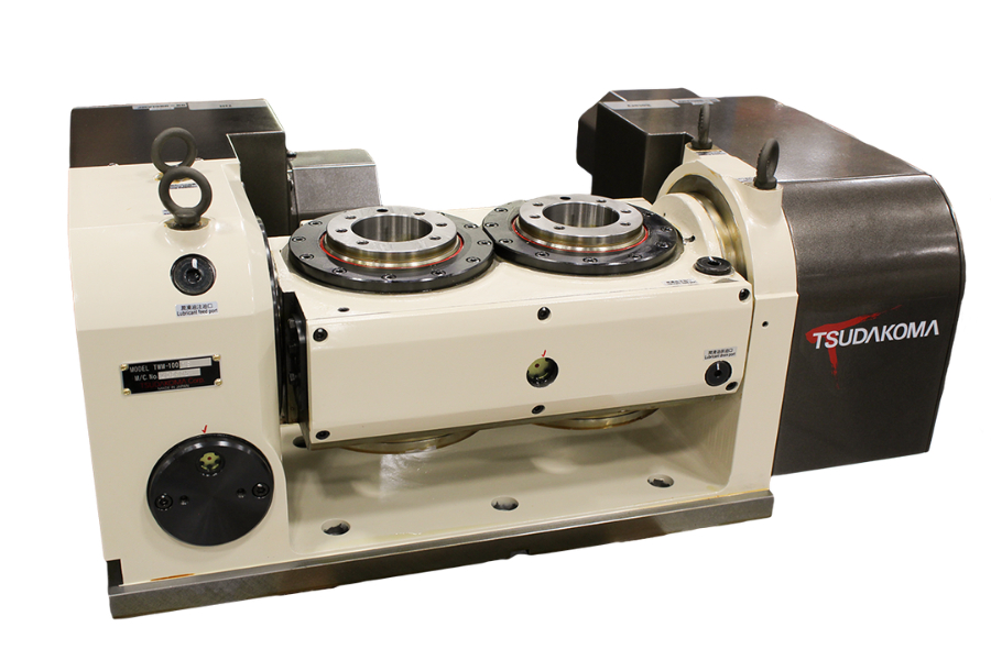
When Precise was looking for a 5-axis solution, it selected a Tsudakoma 12” (304.8mm) Model RBA-320K from Koma Precision Inc., East Windsor, Conn., for its Okuma HMC. In explaining Precise’s choice, Engineering Manager Don Moody said adding a rotary table costs much less than a dedicated 5-axis machine. “It also allows us to get to the center of the part easier.”
Unlike a full 5-axis, trunnion-style machine, an HMC plus rotary table allows setting up parts on the pallet outside the machining area while parts loaded on a second pallet are being machined. This drastically reduces downtime caused by stopping the machine to set up the fixture. The spindle utilization of an HMC can often be more than twice as much as that of a vertical machining center.
“Having two pallets on the HMC increases our efficiency and time management,” Moody said. “The operator is more flexible as to when he can load/unload the part. Plus, the machine is not waiting on the load/unload.”
To maintain the automatic pallet changing capabilities of the HMC, Koma’s Integration Division installed a cable management system on-site. It allows the rotary table to remain connected throughout a pallet change while keeping all the cabling out of the way of fixtures and metal chips. Furthermore, if there are hydraulics or air-sensing lines involved, this system can monitor and actuate automatic fixturing.
Cable management is accomplished with a scissor arm above the pallet that rotates or bends along with the movement of the B-axis on the HMC. On top of the rotary table, a swivel box permits the pallet to rotate ±120° in a standard configuration.
When machining high-quality aerospace parts, high rigidity and positioning repeatability are key. In this case, the Tsudakoma RBA-320K was a good fit because of its hydraulic dual-disc clamping system. This system maintains the fixture and part positioning while the machining center is taking its cuts. The machine is only as accurate as the rotary table, so positioning repeatability throughout the entire production run is critical to making good parts.
Moody confirmed the benefits of a rotary table setup. “We have many Tsudakoma rotary tables, and they all perform very efficiently and reliably. We run them day in and day out, 24/7.”

For a shop that’s looking to boost its vertical machining center capabilities, the addition of a rotary table can be a cost effective way to take productivity to new levels. One company—both a supplier of parts for bottling, automotive and other production processes and a prototype design services firm—found itself with an immediate need for fourth-axis capabilities to fulfill production for a contract it had been awarded.
“We were in desperate need of a rotary table to meet the production demands,” says Don Borman, co-founder of Borman Enterprises (Cleveland, Ohio). But he also saw another important reason to add the rotary table to the company’s equipment lineup. “The bigger part of our business is the manufacturing end, but that gives us the opportunity to house a training center that’s very functional,” he says. The rotary table was also to become a staple in the process of training the skilled CNC programmers, operators and setup people the company needed, allowing them to see fourth-axis machining at work.
In December 2009, Mr. Borman decided it was time to add fourth-axis capabilities. The company ordered a new vertical machining center with a rotary table so it could bring its fourth-axis work in-house and the training center would be able to incorporate fourth-axis machining into the curriculum. About the same time, the company landed a contract for fourth-axis work, but soon discovered the VMC on order wasn’t going to have the table.
“I found out 2 days before the machine was due here that it wasn’t going to have the fourth axis. That was part of the purchase of the VMC—the table.” That’s when he called CNC Indexing (Wakeman, Ohio).
“I was panicking because the machine had just been installed, and I had the job and material, but I couldn’t do the job because I didn’t have the rotary table,” Mr. Borman says. He checked his options through a distributor. Everyone he contacted said it would take 3 months to get the rotary table he needed. He checked into used equipment. No luck. Finally, his wife found CNC Indexing online.
Mr. Borman says, “What other people told me couldn’t be done (interfacing the controls), Jamie Schwarz at CNC Indexing was positive they could do. And they did it.”
He continues, “Unfortunately, we lost that job because I couldn’t get the rotary table that the machine tool distributor had promised me. Had I known earlier about the missing table, I know CNC Indexing would have been able to have it installed in time. They had the tables in stock, and they filled the void.”
Adding a rotary table (fourth axis) or a tilt table (fourth/fifth axes) to a three-axis machine gives a shop the ability to produce multiple face workpieces more easily and quickly. It also provides more flexibility on the type of work that can be produced. A rotary table opens the door for simultaneous rotating and milling of a workpiece, which is needed to perform complex contours and spirals. The most common reason for and the most obvious advantage of adding a rotary table is the ability to access odd angles (down to 0.001 degree) without designing complicated fixturing. Other not so obvious advantages make the rotary table a good choice for many applications:
Higher part accuracy. The more a workpiece is unclamped, rotated and clamped manually in a fixture to access other faces, the greater the buildup of tolerances. A rotary table allows multiple faces to be accessed without moving the workpiece out of a fixture, thus producing features on a part as accurate to each other as the capabilities of the machine and rotary table. This accuracy results in less scrap and higher profits.
Part production time reduction. By adding a rotary table, the cycle time per part is reduced because multiple operations are performed in one clamping. The machine does not need to be stopped so the part can be turned in the fixture. No time is wasted if the operator isn’t standing at the machine to manually rotate the part.
If the same tool is required on multiple faces of the workpiece, it is possible to do so in one tool change. In most cases, it is quicker to rotate the workpiece with the rotary table than to change tools. This reduces the amount of time required for changing tools over the workpiece’s entire production cycle. It may only be seconds, but added up over shifts, weeks, months and years, those seconds turn into hours of saved time. This time savings allows for more parts to be produced or for additional machine time for other work.
Labor savings. Adding a rotary table allows the workpiece to be in production, untouched, for longer periods of time. The operator, then, has time to walk away from the machine and perform other important jobs within the shop. Fewer employees are needed to produce the same amount of output, saving money for the company.
Non-dedicated machine time. The machining center does not have to be dedicated to rotary table work. In the majority of cases, a rotary table will be mounted to the right side of the machine table. The rotary table footprint is such that it leaves the majority of the machine table free to be used for other non-rotary table work. It also allows the machine to be set up for multiple jobs at the same time.
“We put in a proposal at a plant closing to re-train some of the skilled machinists in the CNC area,” says Tim Duffy, CITC director. “We got the project, which started everything. Don got the certification and got the ball rolling.”
By 1993, Borman Enterprises was certified by the State Board of Career Colleges and Schools. The training services were split off from the company to form the CITC. Classes focus on hands-on training, providing students and graduates access to new CNC machine tools and CAD/CAM systems, as well as quality control equipment and tooling.
“When fourth-axis machining comes up in the classroom, we take the students right out to show a live presentation. It’s live—the chips are flying,” Mr. Borman says. “The instructor brings them up to the working environment to go over the slant bed design of the lathe, or he’ll go over to the rotary table and show them, ‘Here’s the fourth axis, and here’s how you machine with it.’
“These are working machines. That’s really the niche of our training. The problem with other types of training—and I’m all in favor of any kind of education someone can get—is that once the students move on and find themselves in a machine shop environment, they might draw a blank. Suddenly, chips are flying, there’s noise, and they draw a blank. We teach in that environment. The class is working at one machine, and there’s one next to it that is making a part. We’re simulating a working environment. We provide timely and productive training that’s real.”
When it was originally installed, the Golden Sun 10-inch rotary table was set up as a typical fourth axis at a right angle for drilling 30 holes on nozzles designed and made by Borman for a large bottling customer.
The company now has the rotary table laid down on a sine bar at a 20-degree angle, which presents the nozzle at a 20-degree angle, and Borman compounds it another 14 degrees. Currently it is not cutting chips, but it’s set up for the next batch of nozzles. Meanwhile, the company has a vise on the other end of the machine table, which allows conventional VMC work.
“Being a job shop, we have to be versatile,” Mr. Borman says. “When this one account wants samples, they need them now. We have to have the setup, which takes 3 hours, ready to go.”
CNC Indexing’s Jamie Schwarz says the compact design of the Golden Sun table helps in that regard. “It’s very easy to work with as far as space. It doesn’t take up the whole machining envelope.” That leaves ample open table space for maneuverability and flexible use.
Mr. Borman says he’s had a good track record with Golden Sun. And the new rotary table did not disappoint. “It’s just a user-oriented, price competitive table. That’s what I look at more than anything. I don’t think we’ve ever had a maintenance issue on the 10-inch table in 3 years. It keeps running and running.” The company has since gained still more capacity by purchasing a new 12.5-inch rotary table.
With 16 CNCs (two dedicated to training) and 20 operators during two shifts, students are scheduled on any machines with open time. “We schedule the students just like we would a job. Right now, both fourth-axis machines are not cutting chips, which is unusual,” Mr. Borman says. “Next week at this time, both will be busy, and we could almost use another one. If it weren’t for our added capacity, we would probably have had to turn down training folks.”
But most of the students aren’t quite ready for fourth-axis work. To date, learning fourth-axis methods is more lecture than hands-on. It can be incorporated into a class project during the standard 17-week program, but Mr. Borman says they can only cover so much.
That’s no surprise to Mr. Schwarz, who’s been in the CNC machining business in one aspect or another since 1994. Setting up machining centers with machine tool accessories throughout the U.S. and training machine operators to use them brings him in contact with a lot of machinists. The skill levels, Mr. Schwarz says, ar


 8613371530291