
centering workpiece on rotary table made in china
Most small rotary tables have some sort of center hole, sometimes with a cylindrical bore but often with a Morse taper. If the part you"re wanting to center has its own center hole, you might be able to make a plug that fits the rotary table center hole and the part center hole.
The more common way of centering a workpiece on a rotary table requires that you measure the difference between workpiece radii that are 180 degrees apart, and then adjust the workpiece location on the rotary table to split the difference. The most common tool used to make the measurements is a dial gage or dial indicator that must be held stationary; most often the dial gage is anchored to the machine spindle while the rotary table base is clamped to the table.
After you center the work on the rotary table by eye, set a dial indicator up to probe the reference surface. Adjust the indicator holder or move the table so that the dial gage plunger is pressed about half way into its range of travel before zeroing the indicator. Now turn the rotary table top and workpiece (as an assembly) a half turn before reading the dial gage.
Now you want to move the workpiece relative to the rotary table surface until the dial gage reads one-half of the second value. Let"s say your two dial gage readings are A. 0.000 inch, and B. 0.138 inch . . . you want to move the workpiece until the dial gage reads 0.069 inch at BOTH positions A and B.
Next, you need to repeat the measure-rotate 1/2 turn-measure-split the difference process at positions C and D, which must be on a line perpendicular to that connecting A and B.
Since it"s about impossible to move the part on the table exactly the right amount in the right direction, it"s vital that you recheck and readjust A and B after you adjust along C and D . . . and then you"ll need to check and readjust C and D again, and so on and so on. While you"re learning, it"ll seem like you"re chasing your tail, but it is a skill you"ll learn.
To reiterate, the important part is that when adjusting the part on the table you need to rotate the part and table together when you make your measurements, NOT the machine table.
Then later, if you need to center the table under the spindle, you rotate the spindle to measure and move the machine table, which has the rotary table and part bolted to it, to make the adjustment.

This website or its third-party tools process personal data (e.g. browsing data or IP addresses) and use cookies or other identifiers, which are necessary for its functioning and required to achieve the purposes illustrated in the cookie policy. To learn more, please refer to the cookie policy. In case of sale of your personal information, you may opt out by sending us an email via our Contact Us page. To find out more about the categories of personal information collected and the purposes for which such information will be used, please refer to our privacy policy. You accept the use of cookies or other identifiers by closing or dismissing this notice, by scrolling this page, by clicking a link or button or by continuing to browse otherwise.

This website is using a security service to protect itself from online attacks. The action you just performed triggered the security solution. There are several actions that could trigger this block including submitting a certain word or phrase, a SQL command or malformed data.

This website is using a security service to protect itself from online attacks. The action you just performed triggered the security solution. There are several actions that could trigger this block including submitting a certain word or phrase, a SQL command or malformed data.

I got an 8" Phase II rotary table 6 or so months ago, with matching 3 jaw chuck, mounting plate and tail stock. It all works fine, though it sure lacks the fit, finish, refinement and silky smooth feel of my 50-60 year old American made mill and lathe to which I"ve grown very fond of.
My rotary table arrived with a broken main crank handle, which is made from very brittle plastic. My seller sent me a replacement promptly via Phase II support, and I learned through the process that is a common problem. Be very careful setting the table down, as the handle extends below the bottom of the table and the weight of the table will easily break the handle. The handle is really easy to replace.
Between the table, and the back plate, they did include a set of T-nuts and hex bolts. However, I seem to recall receiving only 3 of four T-nuts, and one of the T-nuts hadn"t been squished sufficiently to fit the RT slot (machining might be a bit of an over statement). At least one of the hex bolts was too long. Phase II support was very good I found, and they sent me another set of T-nuts and bolts.
Do not attempt to machine any of their T-nuts or keys to fit your needs. If they don"t fit, toss them. I destroyed a milling bit trying to machine the keys that attach to the bottom of the RT to fit my milling table while I discovered how horrible Chinese steel is to work with.
The RT has a MT3 taper. When centering your milling head over the table, I"ve found I get most accuracy if I centre to the MT taper rather than the lip directly above the MT. The lip directly above the MT is out a thou or so to the centre of the table.
I put some way oil in the table which is probably the only oiling I"ll give the unit in its life. Unlike the mill or lathe which I feel a pride and obligation to treat with the greatest of care, there won"t be any lost sleep if I drill into the table by mistake - unless it destroys another milling bit. Im hoping Ill find a good deal on a dividing head some time.
If you figure out what the lever closest to the main crank handle does, and how to work it, let me know. The Chinglish instructions and exploded diagram don"t help. It seems to suggest it might release the crank handle from driving the table, but I havent been able to get it to release.

When using a rotary table on a mill, whether to mill an arc or drill holes in some circular pattern, there are two things that must be done to set up the workpiece. First, the workpiece must be centred on the rotary table. Second, the rotary table must be centred under the spindle. Then the mill table can be moved some appropriate distance and you can start cutting.
You could centre the table under the spindle first, by indicating off the hole in the centre of the table. Then you could mount the workpiece on the table and indicate off the workpiece. There are two problems with this approach. First, you are assuming that the hole in the table is true and centred. That may or may not be true. Second, this approach risks a sort of accumulation of errors, as you"re measuring from two different features (the rotary table"s hole and some feature on the workpiece). My suggestion is to centre the workpiece on the rotary table first, and then centre the rotary table under the spindle.
As shown in this photo, a DTI has been positioned with its tip against the inside of a hole in the workpiece. The DTI is held in the mill spindle, but that"s just for convenience. (When I do this, I put a little wooden wedge between the spindle pulley and the headstock, to make sure the indicator remains stationary.) It could as easily be held on a test stand. Indeed, the measurement doesn"t have to be done on the mill at all.
To centre the workpiece on the rotary table, spin the rotary table and watch for deflection of the indicator pointer. Adjust the chuck jaws as required, until the needle no longer deflects.
After the workpiece is centred on the rotary table, you now turn the spindle by hand, so the DTI tip sweeps the inside of the hole. Adjust the position of the mill table as required until no needle deflection is noted.
Again in this photo, a DTI is measuring from the inside of a hole. As in the previous illustration, the rotary table is spun and the workpiece"s position on the rotary table is adjusted until the DTI shows no deflection.
After the workpiece is centred on the rotary table, you now turn the spindle so the DTI tip sweeps the inside of the hole. Adjust the position of the mill table as required until no needle deflection is noted.
You can, of course, use the pointed end of a centre finder to position over a point on the workpiece. When centring the table under the spindle, if you are indicating off a larger hole or other curved feature, you may need to mount the indicator on a short arm, so you can sweep a large enough radius.
The technical solutions in the embodiments of the present invention will be described clearly and completely with reference to the accompanying drawings in the embodiments of the present invention, and it is obvious that the described embodiments are only some embodiments of the present invention, not all embodiments. Based on the embodiments in the present invention, all other embodiments obtained by a person skilled in the art without creative work belong to the protection scope of the present invention.
Referring to fig. 1, the present invention provides a technical solution: a high-precision rotary table with a centered locking function comprises a base 1, a precision motor 2 and a driving motor 6, wherein the precision motor 2 is fixedly mounted in the middle of the upper portion of the base 1, a rotary table body 3 is fixedly connected to the output end of the precision motor 2, a working table surface 5 is fixedly connected to the middle of the upper portion of the rotary table body 3 through a support rod 4, the rotary table body 3 is of a concave structure, the middle of the rotary table body 3 is arranged in an inclined manner, a gap is reserved between the inner wall of the rotary table body 3 and the outer wall of the working table surface 5, a connecting clamping groove 16 is formed in the lower portion of the rotary table body 3, and the precision motor 2 can drive the rotary table body 3 to rotate conveniently;
referring to fig. 1 and 3, in order to facilitate the centering and locking of the workpiece, a driving motor 6 is installed at the lower middle part of the worktable 5, and a first bevel gear 7 is connected above the driving motor 6, a rotary screw rod 8 is rotatably connected at the inner side of the working table surface 5, a second bevel gear 9 is fixed at the inner end of the rotary screw rod 8, the surface of the working table surface 5 is provided with a slot 19, the surface of the slot 19 is provided with a movable block 10, the second bevel gear 9 at the inner end of the rotating screw rod 8 is connected with the first bevel gear 7 in a meshing way, the rotating screw rod 8 is in threaded connection with the movable block 10, the rotary screw rod 8 and the groove 19 on the surface of the working table surface 5 form a sliding structure in clamping connection, so that the rotary screw rod 8 drives the movable block 10 to move inwards conveniently through the rotation of the driving motor 6, and the workpiece is conveniently locked in the middle;
referring to fig. 1, 2, 4 and 5, for collecting scraps of the device, a suction pump 11 is fixedly installed at the left and right ends above a turntable body 3, a suction cover opening 12 is connected to the inner end of the suction pump 11, the suction cover opening 12 is in a semi-circular structure, the inner end surface of the suction cover opening 12 is tightly attached to the outer wall of a protective screen 13, the protective screen 13 forms a detaching and installing structure in a clamping connection with the surface of the turntable body 3 through a screw, thereby facilitating the material suction of the device, for detaching the material receiving frame 15, the protective screen 13 is installed inside the turntable body 3, a discharge opening 14 is installed below the turntable body 3, a material receiving frame 15 is installed at the outer end of the turntable body 3, the material receiving frame 15 is in a semi-circular structure, the inner diameter of the material receiving frame 15 is matched with the outer diameter of the turntable body 3, and the inner end of the material receiving frame 15 is in a clamping connection with a connecting clamping groove 16 of the turntable body 3, the material receiving frame 15 and the rotary table body 3 are convenient to disassemble.
In summary, in order to facilitate stable installation of the material receiving frame 15, the limiting fixture block 17 may be disposed above the inner side of the connecting slot 16, the limiting fixture block 17 and the inner side of the turntable body 3 form an elastic structure through the spring 18, and the limiting fixture block 17 and the clamping hole 20 formed on the inner surface of the material receiving frame 15 form a clamping structure, so that the material receiving frame 15 can be conveniently and effectively clamped by the limiting fixture block 17, and the use effect of the device is improved.
The working principle is as follows: according to the figures 1 and 3, when the device is used, a workpiece to be machined is placed above a working table surface 5, the driving motor 6 is started to drive the second bevel gears 9 at the inner ends of the rotating screw rods 8 to be meshed with each other through the first bevel gears 7, so that the rotating screw rods 8 symmetrically arranged above the second bevel gears 9 can drive the movable blocks 10 to move oppositely, the movable blocks 10 can extrude the workpiece in the middle, the workpiece can be conveniently locked, and when the device is used, the precision motor 2 can be started to drive the rotary table body 3 to rotate, so that the workpiece can be machined;
as shown in fig. 1, 2, 4 and 5, during processing, by opening the getter pump 11, the getter pump 11 sucks the scraps through the suction hood opening 12, the protective barrier net 13 is installed outside the suction hood opening 12, the scraps can be effectively blocked by the protective barrier net 13, the scraps are prevented from entering the suction hood opening 12, the scraps can fall to the inner side of the lower turntable body 3 through the blocking of the protective barrier net 13, the scraps can be conveniently discharged into the material receiving frame 15 through the turntable body 3 with the inclined inner portion, the material receiving frame 15 is in a semicircular structure, and the material receiving frame 15 and a limit clamping block 17 on a connecting clamping groove 16 on the inner side of the turntable body 3 form a clamping connection disassembly and assembly structure, which facilitates the disassembly of the material receiving frame 15, the above is the operation of the whole device, and the details which are not described in detail in this specification are well known to those skilled in the art.
Although embodiments of the present invention have been shown and described, it will be appreciated by those skilled in the art that changes, modifications, substitutions and alterations can be made in these embodiments without departing from the principles and spirit of the invention, the scope of which is defined in the appended claims and their equivalents.

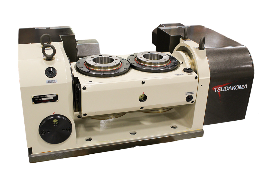
Koma Precision showcases the dual platter Tsudakoma TWM-250 five-axis rotary table. This high precision unit has two 10" platters that can be equipped with rotary unions for hydraulic or pneumatic work holding actuation. The unit can be setup for 12-16" between platters, which Koma says enables for a variety of work holding and workpiece shapes and sizes.
The TWM series is said to be ideal for high-production single or dual spindle VMC’s that require five-axis machining. The TWM series unit can be setup for simultaneous five-axis movement or 4+1, enabling the machine to get around five sides of the workpiece. The hydraulic brake on the tilt axis reportedly provides 3100 Nm of brake torque, which enables the machine to take heavier cuts at more aggressive speeds and feeds while maintaining the accuracy of the part. According to Koma, the machine tool is only as accurate as the work holding and rotary table; therefore, the rigidity is critical to the entire throughput rate and quality of the cutting process.
The International Manufacturing Technology Show runs September 12 - 17, 2022 at McCormick Place in Chicago. Register for IMTS today to start planning your show.
Mitsui Seiki’s compact PJ 303X machining center, to be highlighted at IMTS 2022, provides high precision, speed and versatility for critical parts like lens molds, medical products and EDM electrodes.
The specific embodiment one: in conjunction with Fig. 1, Fig. 2 and Fig. 3 present embodiment is described, the described a kind of sharp blade diamond cutter rotation center alignment method based on optical imagery reconstruct of present embodiment comprises that concrete steps are as follows:
Step 1, with CCD optical imaging device 7 be arranged on sharp blade diamond cutter 8 directly over, described sharp blade diamond cutter 8 is fixed on the rotary table 6 on the four-axle linked ultra-precise cutting lathe by tool mounting 9, CCD optical imaging device 7 has two kinds of multiplication factors at least, wherein a kind of multiplication factor is 15~25 times, another kind of multiplication factor is more than 200 times, and CCD optical imaging device 7 multiplication factors are adjusted to 15~25 times;
Imaging is carried out in the point of a knife zone of step 2,7 pairs of sharp blade diamond cutters 8 of CCD optical imaging device, sets up two dimensional surface coordinate system XOZ at the optical imagery that obtains, and the coordinate that obtains A point place, point of a knife position in the image is (x
Step 3, make rotary table 6 be rotated in a clockwise direction angle [alpha], the point of a knife zone imaging again of 7 pairs of sharp blade diamond cutters 8 of CCD optical imaging device obtains the coordinate (x at B point place, point of a knife position in the optical imagery
The coordinate that the A point that step 4, two width of cloth optical imagerys that obtain according to step 2 and step 3 obtain and B are ordered: try to achieve P point coordinates value; The coordinate figure of being ordered by B point and P subtracts each other, and finally obtains when the point of a knife point position B of paracone blade diamond cutter 8 and the coordinate difference between the axis of rotation P: Δ 1=x
Step 5, according to the coordinate difference that step 4 obtains, the position of adjusting sharp blade diamond cutter 8 by tool mounting 9 makes it near axis of rotation P, finishes the heart is operated.
The position of CCD optical imaging device 7 in lathe coordinate system need not to fix, and more fixed monitoring imaging was more convenient than in the past.Drive the principle that sharp blade diamond cutter oscillation forms deviation based on CCD optical imaging device 7, utilization by rotary table 6, obtain the difference between point of a knife point and rotary table 6 axle center, realize precisely to the heart with this.
To heart principle and measurement: the sharp blade diamond cutter 8 shown in Fig. 1 is installed on the tool mounting 9, and is fixed on the rotary table 6, so sharp blade diamond cutter can be realized swing or the location of certain angle under the drive of rotary table 6.At first, sharp blade diamond cutter rotation W1 place, tool position extremely as shown in Figure 2, concrete angle can not be restricted.Suppose that point of a knife point is A, adopt the cutter point of a knife zone of 7 pairs of this moments of CCD optical imaging device to carry out imaging, and on computers optical imagery is set up coordinate system shown in the lower left corner among Fig. 2, and measure X and the Z direction coordinate figure at point of a knife A point place.Then, suppose that the axle center of rotary table 6 shown in the point of the P among Fig. 2, makes sharp blade diamond cutter along the rotation direction of arrow shown in Fig. 2, the α that rotates to an angle, this angular dimension is known, even also cutter rotates to W2 place, position as shown in Figure 2.This moment, the line of symmetry of sharp blade diamond cutter was in vertical state, suppose that point of a knife point is B, adopt the CCD optical imaging device that imaging is carried out in the point of a knife zone of this moment then equally, and on computers to the coordinate system of optical imagery foundation shown in the lower left corner among Fig. 2, and measure X, the Z direction coordinate figure at point of a knife B point place.At last, based on two width of cloth optical imagerys in the cutter point of a knife zone before and after the rotation, can set up geometrical relationship as shown in Figure 2, namely the anglec of rotation α of cutter equates with ∠ APB among the figure.Therefore, as long as gather out the concrete coordinate figure in 2 the same coordinate systems under identical picture size (or identical multiplication factor and equal resolution) of A, B, and concrete angle and the point of a knife angle β of cutter rotation, just restructural blade diamond cutter full to the brim the swing before and after several picture, and can according to the swing before and after geometrical relationship try to achieve the concrete coordinate position that swinging center P is ordered.
The specific embodiment two: what the described a kind of sharp blade diamond cutter rotation center alignment method based on optical imagery reconstruct of present embodiment and embodiment one were different is, described center alignment method is further comprising the steps of: CCD optical imaging device 7 is adjusted to multiplication factor more than 200 times, repeating step two, step 3 and step 4, adjust the position of sharp blade diamond cutter 8 again, finish the heart is operated.
The step that present embodiment increases is described after operation is finished to the heart at embodiment one, increases the imaging multiplication factor of CCD optical imaging device 7, and then carries out once heart operation is improved the precision to the heart.
The advantage of present embodiment is: carry out a hypocone blade diamond cutter point of a knife point and axis of rotation slightly to the heart, can guarantee when the imaging multiplication factor of the high multiple of employing is carried out the point of a knife regional imaging, to be unlikely to deflect away from the imaging scope after the rotation; Undertaken the heart by above-mentioned steps again, with finish sharp angle of throat tool point of a knife point and B axle rotary table axle center precisely to the heart.If want to realize degree of precision to the heart, can adopt imaging device under the high multiple according to heart scheme being carried out repeatedly the heart, with checking repeatedly precisely to the result of the heart.The result shows: when the imaging scope was 781.9 μ m * 585.8 μ m, corresponding 250 times of multiplication factors, pixel-matrix 1600 * 1200 precisely were better than 0.5 μ m to heart precision.If resolution ratio, multiplication factor and the image processing accuracy of CCD optical imaging device further improve, precisely the precision to the heart also can be higher.
The specific embodiment three: illustrate that in conjunction with Fig. 2 the detailed process of trying to achieve P point coordinates value described in embodiment one step 4 is: make O that point is initial point, the A point coordinates is (x
2), the coordinate of establishing unknown point P for (x z), makes vertical line with axis of rotation P point to straightway AB, and intersection point is the C point, by the formed geometrical relationship of rotating deviation, can get:
R in the formula---sharp blade diamond cutter 8 is with the radius of rotary table 6 rotary oscillations, l---straightway AB length, α---dextrorotation gyration; A point coordinates (x
The specific embodiment four: the position of adjusting sharp blade diamond cutter 8 by tool mounting 9 in embodiment one step 5 makes its process near axis of rotation P be: adjust sharp blade diamond cutter 8 according to coordinate difference Δ 1 in X-direction, adjust sharp blade diamond cutter 8 according to coordinate difference Δ 2 in Z-direction again.

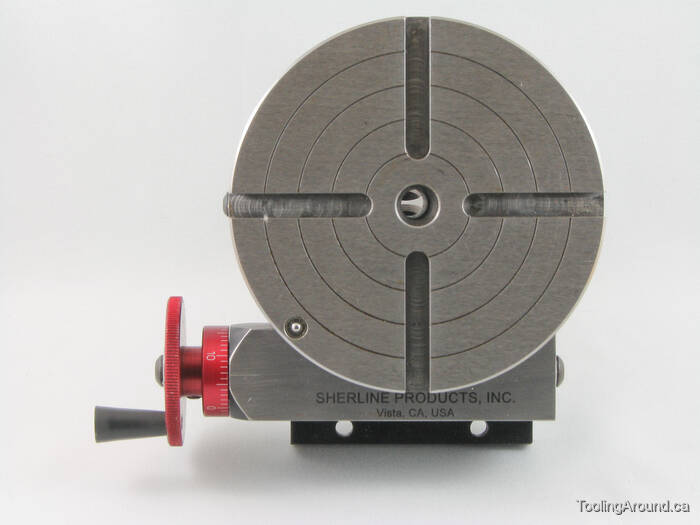
A rotary table is a precision work positioning device used in metalworking. It enables the operator to drill or cut work at exact intervals around a fixed (usually horizontal or vertical) axis. Some rotary tables allow the use of index plates for indexing operations, and some can also be fitted with dividing plates that enable regular work positioning at divisions for which indexing plates are not available. A rotary fixture used in this fashion is more appropriately called a dividing head (indexing head).
The table shown is a manually operated type. Powered tables under the control of CNC machines are now available, and provide a fourth axis to CNC milling machines. Rotary tables are made with a solid base, which has provision for clamping onto another table or fixture. The actual table is a precision-machined disc to which the work piece is clamped (T slots are generally provided for this purpose). This disc can rotate freely, for indexing, or under the control of a worm (handwheel), with the worm wheel portion being made part of the actual table. High precision tables are driven by backlash compensating duplex worms.
The ratio between worm and table is generally 40:1, 72:1 or 90:1 but may be any ratio that can be easily divided exactly into 360°. This is for ease of use when indexing plates are available. A graduated dial and, often, a vernier scale enable the operator to position the table, and thus the work affixed to it with great accuracy.
Rotary tables are most commonly mounted "flat", with the table rotating around a vertical axis, in the same plane as the cutter of a vertical milling machine. An alternate setup is to mount the rotary table on its end (or mount it "flat" on a 90° angle plate), so that it rotates about a horizontal axis. In this configuration a tailstock can also be used, thus holding the workpiece "between centers."
With the table mounted on a secondary table, the workpiece is accurately centered on the rotary table"s axis, which in turn is centered on the cutting tool"s axis. All three axes are thus coaxial. From this point, the secondary table can be offset in either the X or Y direction to set the cutter the desired distance from the workpiece"s center. This allows concentric machining operations on the workpiece. Placing the workpiece eccentrically a set distance from the center permits more complex curves to be cut. As with other setups on a vertical mill, the milling operation can be either drilling a series of concentric, and possibly equidistant holes, or face or end milling either circular or semicircular shapes and contours.
* To create large-diameter holes, via milling in a circular toolpath, on small milling machines that don"t have the power to drive large twist drills (>0.500"/>13 mm)
* With the addition of a compound table on top of the rotary table, the user can move the center of rotation to anywhere on the part being cut. This enables an arc to be cut at any place on the part.
Additionally, if converted to stepper motor operation, with a CNC milling machine and a tailstock, a rotary table allows many parts to be made on a mill that otherwise would require a lathe.

CNC rotary table is a device used to assist the workpiece in multi angle machining on the machining center. One-time clamping and multi-faceted machining can ensure the position accuracy between workpiece features and improve the use efficiency of the machine tool. In contrast, the standard machining center has only three axes x, y and Z. after adding four axes, it can process workpieces with complex features, such as blades, cams, etc.
In practical application, it is necessary to match with some additional accessories to meet the requirements, such as disc tail stock, chuck, zero point system, controller mode, braking device, etc
If the work piece is made of aluminum, copper materials, and the machining cutting force is small, you can choose harmonic gear, DD motor type rotary table, or choose worm or roller cam structure, and use pneumatic brake.
If the parts are made of cast iron, steel and other materials, it is recommended to select the rotary table with worm or roller cam structure, and judge whether to add hydraulic brake according to the cutting force.
2. If it is odd and abnormal, and more than 2 workpieces are processed at one time, please purchase additional disc tailstock. In addition, L-shaped block, large base plate and medium plate can be made according to actual needs
(1). Worm, roller cam and DD motor rotary tables have different accuracy and retention life.which should be determined according to the workpiece accuracy
(2).If accuracy specified in mm, check for the diameter at which the accuracy is required.Convert Indexing Accuracy of the Rotary Table specified in arcsec to mm at the diameter where the operation is to be carried out,(A = Tan Ө x R),Ө = Indexing Accuracy (Ex: +/- 15” (30”sec)),R = Radius at which the operation to be carried out ,A = Accuracy in μ
(2) Confirm the total load that the machine tool can bear, and then add up the weight of the preselected rotary table, tail stock, L-Block, medium plate (bridge plate), base plate, work piece, fixture and so on,
(3) If it is overweight, judge the material of the workpiece first. If it is aluminum alloy or other light materials,which caused by the long shape support joint or large rotation diameter of the work piece, you can change the indexing disc to a smaller model and add a cushion block to reduce the weight, so that the price is low and can meet the requirements of the rotation diameter of the work piece.
After moving the Y-axis of the machine tool to the origin, measure the distance from the center of the worktable to the metal plate of the moving door of the machine tool, check the size from the center of the disk surface of the indexing plate to the tail end of the motor cover, and judge whether the motor cover will interfere with the metal plate of the machine tool. If there is interference, change the motor cover
First confirm the length of the machine tool workbench, especially when the scheme of disc tail stock and bridge plate is selected, the bottom plate is 200mm larger than the machine tool workbench at most, that is, 100mm will protrude on both sides, which is the maximum allowable protruding position
The rotary table is generally composed of several parts as shown in the figure below: ① rotary table house, ② motor of the fourth axis, ③ cable with sheath, ④ cable without sheath, and ⑤ driver. In addition to the five major hardware, the interface must be reserved for the fourth axis on the machine tool.
(2).If the machine tool does not have interfaces reserved for the fourth axis, but wants to add the fourth axis later, please ask the machine tool manufacturer to open the interface or select the single axis controller, but the single axis control system cannot be linked with any axis of the X, Y and Z axes of the machine tool. Only after the rotation of the fourth axis is completed, the other three axes can operate.
when purchasing rotary table and disc tail stock, and designing the cradle type fixture, when eccentric machining is caused by the force arm (A) exceeding the disc surface (the higher the cushion is, the longer the force arm A is, which is not the load of mechanical common sense), it will seriously wear the rotary table reducer. Please be careful

This application claims priority to German patent application DE 10 2016 118 572.8, filed Sep. 30, 2016, the entire content of which is incorporated herein by reference. TECHNICAL FIELD
The present invention relates to a rotary table for a coordinate measuring apparatus and to a coordinate measuring apparatus with a rotary table. BACKGROUND
Coordinate measuring apparatuses are used for measuring components and have a workpiece holder for mounting a workpiece or component to be measured. The workpiece holder is usually fixedly attached to a base of the coordinate measuring apparatus or mounted rotatably about an axis of rotation with respect to the base. Coordinate measuring apparatuses usually have a probe head that can be moved in three spatial directions and a probe element for probing the component, so that by contacting the workpiece or component it can be measured. The probe head of such a coordinate measuring apparatus can be moved along three independent spatial directions X, Y and Z in a way corresponding to a Cartesian XYZ coordinate system, in order to be able to reach any desired location within a measuring space.
If a rotary table is provided on the coordinate measuring apparatus for mounting the workpiece or component, the component to be measured can additionally be rotated into different positions. For this purpose, the rotary table has a rotatable main rotary table body for receiving the workpiece, which is rotatable about a rotary table axis of rotation. With rotatable mounting of the workpiece, however, the measured values that are captured with respect to the Cartesian XYZ coordinate system of the coordinate measuring machine must be converted into a coordinate system of the workpiece that rotates with the axis of rotation. It is therefore necessary for an exact measurement of the component that the position and orientation of the rotary table axis is known precisely in relation to the coordinate system of the coordinate measuring apparatus. The calibration of the axis of rotation is provided in DIN EN ISO 10360-3 for coordinate measuring apparatuses with additional axes of rotation, i.e., the determination of the position and orientation of the rotary table axis in relation to the coordinate system of the coordinate measuring apparatus.
Various methods for determining the position and orientation of the rotary table axis are available for this purpose, such as for example the so-called “one-sphere method”, “the two-sphere method” or “the calibration of the rotary table axis by a test cylinder”. These and further methods are described for example in WO 02/090879 A2 and U.S. Pat. No. 9,683,827.
In the case of coordinate measuring apparatuses with rotary tables, a distinction is also made between rotary tables with face plates and rotary tables with a clamping chuck. Rotary tables with face plates are usually used for relatively large components, which are fastened on the face plate by clamping means. For this purpose, the face plate has a plurality of fasteners, such as threaded bores, by way of which the clamping means can be fastened on the face plate. The clamping means can in this case be positioned on the face plate individually and independently of one another, so that even unsymmetrical workpieces can be received. In this way, a flexible arrangement of differently dimensioned workpieces is possible.
Often used on the other hand for relatively small components to be measured are rotary tables with a clamping chuck, such as a jaw chuck, in the case of which the clamping elements are clamped together such that they preferably receive the workpiece in the clamping chuck receptacle in a self-centering manner. For this purpose, at least two or three or more clamping elements, such as clamping jaws, are displaceably arranged in a main clamping chuck body, these elements being able to be moved and clamped by a common drive. In the case of small rotary tables, the clamping chucks, and in particular the main clamping chuck bodies, can cover the entire rotatable main rotary table body of the rotary table.
For such relatively small rotary tables with a clamping chuck, a reference object, known as a master, is arranged in the component holder, such as for example the jaw chuck, for the calibration of the rotary table axis. For example, for the calibration by the one-sphere method, a master with a sphere arranged eccentrically in relation to the rotary table axis is fastened in the jaw chuck.
Since, however, the rotary table only has one component holder, for calibrating the rotary table axis with a correspondingly offset sphere holder (master) it is necessary to unclamp a component that is on the rotary table and fit the master. This is particularly labor intensive whenever it is necessary for the calibration of the rotary table axis to be frequently repeated (recalibration), for example due to temperature influences or the like, since this necessitates a frequent change between the component to be measured and the master, which involves a great expenditure of time for the user.
In the case of a rotary table with a clamping chuck, there is also the problem that the clamped-in master does not have a definite position with respect to the rotary position in the rotary table or the corresponding component coordinate system, so that automated measurement of the rotary table axis is not possible. SUMMARY
It is an object of the present invention to provide a rotary table for a coordinate measuring apparatus and a corresponding coordinate measuring apparatus that allows easier calibration and recalibration of the rotary table axis of a rotary table with a workpiece holder in the form of a clamping chuck.
To solve the problems described above concerning the calibration of the rotary table axis for rotary tables with a clamping chuck, such as for example a jaw chuck, the rotary table is provided with at least one master with which a calibration of the rotary table axis is possible or with a possibility for fastening a master outside the clamping chuck receptacle for receiving the workpiece to be measured.
The master may be arranged fixedly or detachably on the rotary table. In the case of a fixed arrangement, the master may be arranged in a material-bonding manner, for example by an adhesive connection, while in the case of a detachable arrangement an interlocking and/or frictionally engaging arrangement is possible. In particular, threaded bores in which a corresponding master can be arranged by screw connections may be arranged on the rotary table.
The master and/or the single or multiple fasteners for fastening a master may be arranged eccentrically in relation to the rotary table axis and may in particular be arranged on an imaginary circular line around the rotary table axis. In the case of multiple masters and/or fasteners for fastening a master, at least two different imaginary circles with different circle radii in relation to the rotary table axis may be provided for the arrangement of the masters and/or the fastener therefor.
The master and/or the fastener for the master may be arranged on the rotary table in the main rotary table body or on the clamping chuck, in particular a jaw chuck, and preferably on the main clamping chuck body.
The master may protrude from the rotary table or the main rotary table body or the clamping chuck in an axial or radial direction with respect to the rotary table axis or a fastening device for the master may be arranged such that the arranged master protrudes from the rotary table or the main rotary table body or the clamping chuck in an axial or radial direction.
The masters may be spherical bodies that can be arranged on the rotary table or jaw chuck by way of a rod. Other configurations, such as cylinders, cones, inner cones or other curved or any desired areas are also conceivable. Here, the corresponding form may be formed directly on the main rotary table body or the clamping chuck, for example by forming a depression or spherical cap in the corresponding components of the rotary table.
The configuration of the master may be chosen in particular such that, as far as possible, the master does not disturb a component arranged in the workpiece holder or the jaw chuck of the rotary table and does not collide with it or hamper or hinder the measurement with a stylus. BRIEF DESCRIPTION OF THE DRAWINGS
FIG. 1 shows a coordinate measuring apparatus 1 according to an exemplary embodiment of the present invention. The coordinate measuring apparatus 1 includes a support structure with a movable gantry support 2, movably received in which there is in turn a carriage 3, on which a measuring system 5 is arranged in a vertically movable receptacle 8. The measuring system 5 may have at least one contactless, for example optical, capacitive or inductive, sensor and/or at least one tactile sensor, with which an object 9 to be measured can be sensed. In the case of an optical sensor, this can take place in a contactless manner, whereas with a tactile sensor the dimensions and/or form of the object 9 to be measured is/are determined by corresponding contact with the object 9 to be measured.
The gantry support 2 is movable along a rail arrangement including rails 4, the longitudinal extent of the rails 4 corresponding to the X direction, so that the measuring system 5 can be adjusted in the X direction by moving the gantry support 2 along the rails 4. The carriage 3 can be moved in the gantry support 2 in a direction transverse to the X direction, to be specific the Y direction, a movement of the measuring system 5 with the receptacle 8 that is vertically movable in the carriage 3 perpendicularly in relation to the plane defined by the X and Y directions additionally being possible, so that the measuring system 5 can be moved along the coordinate axes X, Y and Z to any desired point in the measuring space defined by the coordinate measuring apparatus 1.
FIG. 2 shows a plan view of a rotary table 9, which has as a workpiece holder a three-jaw chuck with three clamping jaws 11, which in their middle define a receiving space 12 for the component to be measured. The rotary table axis of rotation, about which the rotary table 9 can be rotated, runs through the centre of the rotary table 9 or the receiving space 12.
A master or a fastener 13 for a master for calibrating the rotary table axis of rotation is arranged on a circular line around the rotary table axis of rotation that is represented by a dashed line. In the exemplary embodiment shown, the fastener 13 is a threaded hole 13 into which the master can be screwed.
The master 14, which can be screwed into the threaded hole 13, is shown in FIG. 3. It is a spherical body including a sphere 15, which is arranged at one end of a shaft 16, a threaded portion 17, with which the spherical body can be screwed into the threaded hole 30 of the rotary table 9 in order to be measured for the calibration of the rotary table axis of rotation, being formed at the other end of the shaft 16.
Although the present invention has been described in detail by way of the exemplary embodiments, it is obvious to a person skilled in the art that the invention is not restricted to these exemplary embodiments but rather that modifications are possible such that individual features can be omitted or different types of combinations of features can be performed, as long as there is no departure from the scope of protection of the appended claims. The present disclosure includes all combinations of the individual features presented. LIST OF REFERENCE NUMERALS


 8613371530291