
centering workpiece on rotary table quotation
When using a rotary table on a mill, whether to mill an arc or drill holes in some circular pattern, there are two things that must be done to set up the workpiece. First, the workpiece must be centred on the rotary table. Second, the rotary table must be centred under the spindle. Then the mill table can be moved some appropriate distance and you can start cutting.
You could centre the table under the spindle first, by indicating off the hole in the centre of the table. Then you could mount the workpiece on the table and indicate off the workpiece. There are two problems with this approach. First, you are assuming that the hole in the table is true and centred. That may or may not be true. Second, this approach risks a sort of accumulation of errors, as you"re measuring from two different features (the rotary table"s hole and some feature on the workpiece). My suggestion is to centre the workpiece on the rotary table first, and then centre the rotary table under the spindle.
As shown in this photo, a DTI has been positioned with its tip against the inside of a hole in the workpiece. The DTI is held in the mill spindle, but that"s just for convenience. (When I do this, I put a little wooden wedge between the spindle pulley and the headstock, to make sure the indicator remains stationary.) It could as easily be held on a test stand. Indeed, the measurement doesn"t have to be done on the mill at all.
To centre the workpiece on the rotary table, spin the rotary table and watch for deflection of the indicator pointer. Adjust the chuck jaws as required, until the needle no longer deflects.
After the workpiece is centred on the rotary table, you now turn the spindle by hand, so the DTI tip sweeps the inside of the hole. Adjust the position of the mill table as required until no needle deflection is noted.
Again in this photo, a DTI is measuring from the inside of a hole. As in the previous illustration, the rotary table is spun and the workpiece"s position on the rotary table is adjusted until the DTI shows no deflection.
After the workpiece is centred on the rotary table, you now turn the spindle so the DTI tip sweeps the inside of the hole. Adjust the position of the mill table as required until no needle deflection is noted.
You can, of course, use the pointed end of a centre finder to position over a point on the workpiece. When centring the table under the spindle, if you are indicating off a larger hole or other curved feature, you may need to mount the indicator on a short arm, so you can sweep a large enough radius.

It"s dead simple and fast. After 3 times you can do this in 5 minutes tops..if not you"re fired!! You have to do this running a Troyke or Advance top cross slide rotary table as they don"t have centering plugs, holes or that nonsense and the tops are square. Most people never use these versatile cross slides or even know they exist and thus are unaware of this method. This is straight from the Advance operators manual and it works.
When we would have a mold that was on the table and then was to be picked up in the morning we always re-indicated to make sure some putz didn"t move the table......now how you going to re-indicate the center hole with your half done part covering it.....simple, see above.

Fig. 4—On this tilting rotary table, one servo controls rotation, another controls tilt. Both servocontrols are slaves to the CNC with RS-232 communication, providing five-axis capability from a standard three-axis CNC.
Fig. 1—Modern rotary tables such as this one from SMW Systems have large, widely spaced spindle bearings, large diameter wormwheels and built-in spindle brakes.
If you want to make parts similar to the complex valve body (upper left), an indexer using M-code, RS-232, or “full fourth axis” control is appropriate. Only positioning and rotary cutting moves are required. The center workpiece is a cam that requires simultaneous rotary and linear moves. You’ll need full four-axis control for such workpieces. If you want to do parts similar to the impeller on the right, the contour cutting will require simultaneous five-axis machining.
Many plant managers and shop owners dream of having the latest horizontal machining center (HMC) with all its features, benefits and sophisticated capability. While typical HMC features such as an automatic pallet changer and a 100+ cutting tool magazine are valuable, perhaps the most valuable characteristic is the HMC’s ability to machine on more than one side of the workpiece due to a built-in indexer or full fourth axis.
On complex workpieces that require machining on surfaces not 90 or 180 degrees from each other, indexing or fourth-axis rotation is almost essential to produce the piece. Even when rectangular workpieces with all surfaces 90 or 180 degrees from each other are put on a tombstone, the HMC’s built-in fourth axis of rotation creates a productivity advantage. This is true even if machining on more than one side of the part is not essential.
Any time you can increase the “run cycle,” do more cutting in one operation and avoid handling the workpiece, productivity goes up. Workpiece accuracy also improves. Unclamping and refixturing a workpiece to present a different surface to the cutting tool is always going to introduce some error.
The high cost of horizontal machining centers compared to the incredible values available today in vertical machining centers puts horizontals out of reach for many shops. Fortunately, today there are several suppliers of quality accessories that allow the VMC shop to equip its verticals with indexers, fourth axes and tombstones. These add-ons really work and give many of the benefits of an HMC at a fraction of the price.
Earlier rotary tables and indexers didn’t have the accuracy, rigidity or control flexibility of today’s models. Many shops that tried using indexers in the past had been disappointed in the performance of the older models and abandoned their use in favor of multiple operations, multiple holding fixtures and multiple handlings of the workpiece. They decided that the manual, multiple-operation process was better than trying to use ineffective early model indexers and rotary tables. Today, the situation is different. Manufacturers now offer units that are very accurate, very rigid and have a variety of control and interface options.
The best indexer and control system for you depend on the work you need to do. As with most things, different designs compromise certain capabilities to gain others. Unless you understand these trade-offs, you are at risk of selecting something other than the best system for your requirements. Let’s see what’s available, review the differing capabilities and discuss the advantages and disadvantages of each design. Once you understand the options, you can evaluate them against your requirements and then consider prices and suppliers.
Of course, such a system does not exist. Add the “lowest price from the supplier that gives the best service and support” component and it probably never will exist.
Terminology in the area of indexers is not standard. Terms such as fourth axis, indexer, rotary table and so on are used interchangeably by different machine tool and accessory companies. So, when selecting and buying, you must ask a few questions before assuming you know what you’re going to get. Also, beware of terms such as “precision,” “high precision,” “accurate,” and “rigid.” Is the “brake torque” specification some absolute break away spec or the torque at which some “unacceptable” amount of rotary deflection occurs? Is the “ten arc seconds” accuracy specification certified every one degree, or is it inspected only every 15 degrees? There are no industry standards for specifications and testing. So ask questions and deal with a supplier in which you have confidence, or buy with a guarantee of performance to make your parts.
We’ll start with the mechanical hardware and discuss the electronic control options later. There are at least three common mechanical indexer/rotary table types.
These tables provide infinite positioning as well as the possibility of rotary cutting. A servomotor controlled directly either by the CNC or by a secondary servocontrol rotates a wormscrew, which drives a wormwheel on the rotary table spindle.
The absolute position accuracy of these systems is a function of the quality (precision and accuracy) of the wormgear set (wormscrew and wormwheel), the accuracy and resolution of the servosystem, and the means of servoposition feedback. Most of these servosystems utilize an encoder to monitor the position of the motor rather than the rotary spindle directly. To eliminate any inaccuracies in the wormgears and servo system, some high-end systems use a glass scale or other encoder directly on the rotary spindle to monitor actual rotary spindle position. Figure 1 (at right) shows a typical wormgear rotary table cross section.
If controlled directly by the machine tool’s CNC, they are most commonly referred to as a “full fourth axis.” A full fourth axis has the advantages of having only one CNC program, no programming required by the operator on the shop floor, minimum chance of a crash due to operator error, and the ability to make simultaneous rotary and X, Y or Z moves to do true helical milling operations as required by some more exotic workpieces.
Claims of position accuracy are often misleading since there are no industry standards. Although some manufacturers test and certify absolute position accuracy every one degree, most do not state exactly what their specification means.For all except those few expensive systems with glass scales directly on the rotary spindle, any accuracy specification is for a new table before it has been subjected to any “crashes,” which are not uncommon. Even seemingly small crashes can damage wormgear sets.
Typical infinite positioning wormgear systems utilize a friction brake to hold position against cutting forces. When cutting forces are applied directly on the rotary spindle centerline, friction brakes are generally adequate for most work. However, when cutting forces are applied to workpieces far off centerline, such as on the edge of a part on a tombstone fixture, the resulting torque on the rotary spindle can cause it to deflect. This result is especially likely when heavy cuts produce high thrust forces.
These indexers offer discrete positioning only. Depending on the number of teeth on the face gear, the minimum increment of index might be 15 degrees, 5 degrees or 1 degree. Whatever the minimum increment, only workpieces with angles representing some multiple of the minimum can possibly be machined.
Face gear mechanisms used in indexers are similar to those most commonly found in the turrets of CNC lathes, which by function must index very accurately and very rigidly to withstand the high cutting forces the lathe turret encounters. Face gear mechanisms generally fall into two categories, the two-piece and the three-piece design. Two-piece designs require the face plate of the indexer to “lift” to disengage the face gears. Three-piece designs maintain the same accuracy and rigidity of a two-piece without the need to “lift” the faceplate. In Figure 2 (at right), note the massive face gear that locks the indexer spindle in position.
Assuming it’s a quality face gear set, absolute position accuracy is superb and is maintained for the life of the indexer almost in spite of any “crashes” that might occur. Units with true absolute angular position accuracy of 5 arc seconds or less are available. These units are ideal for the highest precision work such as line boring half way from one side, then indexing 180 degrees and line boring half way from the other side.
Some face gear systems use a servodrive to achieve approximate position and then rely on the face gear for final accurate positioning. These systems are bi-directional and fast. Any random move can be programmed with one simple command. Some other systems use a pneumatic piston to rotate to the approximate position. Typically, these systems rotate only in one direction. All moves must be equal and may require a pause to utilize more then one M-code signal to achieve position. These work but can be tedious to program, set up and operate. They are more prone to crash due to operator error then servodriven units.
These indexers are becoming a thing of the past. They have all the disadvantages of the pneumatic piston driven incremental face gear indexers. Plus, compared to face gear units, they are neither particularly accurate nor rigid. Index positions are usually limited to 15-degree increments. Position is controlled by a pin in a hole or more often by a dog in a notch on the outside of a ring.
Whether you select an infinite positioning wormgear rotary system or a facegear system as the best mechanical design for your work, your next decision involves how you will control the rotary axis.
With a pneumatic incremental indexer, you probably will have no choice. Your machine’s CNC will control the indexer by communicating with a special indexer control via an M-code.
If you select a system with a servodrive, you have three choices: 1.) direct “full fourth axis” using only the machine’s CNC, 2.) an M-code command from the CNC to a separate rotary control, or 3.) RS-232 communication between the machine’s CNC and a separate rotary control. Each of these choices has advantages and disadvantages.
A single, four-axis CNC is the easiest to use and provides the most control. Four-axis CNC is best for certain kinds of workpieces. Full four-axis control systems are usually ordered for delivery with a new machine. Systems can be retrofitted; however, retrofitting is complicated and expensive. The advantages of a single four-axis control are numerous, and the disadvantages are primarily related to cost.
The single CNC constantly tracks all three linear axes (X,Y,Z) and the rotary axis. This provides the ability to do precise helical cutting with simultaneous rotary and X, Y or Z moves.
While a few machine builders offer a full four-axis control with rotary table for about 10 percent of the base price of the machine, most charge more than 20 percent.
Very few machine builders make it easy to retrofit a full four-axis rotary table. For most builders, retrofitting is a complicated process, and the cost typically exceeds 30 percent of a base machine price.
The motor for the rotary axis must be matched to the servodrive of the CNC. Because cable connections are not standard from one machine builder to another, rotary tables can not generally be used on more than one machine.
Some applications may require the accuracy and rigidity of a face gear system. However, many machine builders don’t offer face gear systems with a full four-axis control, although such systems are feasible.
An M-code actuated system provides a fourth axis of motion by combining a standard three-axis CNC with a rotary table or face gear indexer that has its own separate rotary servocontrol. The rotary program is entered and stored in the separate rotary servocontrol. The CNC communicates with the rotary control via an M-code. When the rotary control receives the M-code signal, it executes the next rotary move stored in its memory, then sends a signal back to the CNC, telling it that the move has been completed.
Typically, the rotary program includes many separate rotary moves. One move might be a simple index to position at full rapid speed. Another might be a slower rotary move to machine a groove or other feature on the workpiece. Figure 3 (at right) shows a typical rotary servocontrol system.
High quality M-code controlled systems are available from several suppliers for a price of about 10 percent of a base machine price. (For example, a 5C rotary system at $6,000; a 6-inch faceplate system at $7,000; a 9-inch system at $10,000; and so on).
Requiring only one M-code, 110V power and an air line for operation, these systems can be retrofitted to almost any CNC machine, typically with less than a day of downtime.
Systems can be moved from one machine to another as long as the next machine can issue M-codes. A shop with multiple machines and multiple rotary systems can select the best system for each job regardless of the machine. For example, a small indexer can be used for small parts to avoid cutting tool interference problems and to minimize indexing times. A big indexer can be used for big parts. A face gear indexer can be used when the maximum in accuracy and rigidity are needed and the work can be accommodated by multiples of 5 degrees of index.
The machine operator needs to enter the rotary program into the rotary servocontrol, or select the right program if it’s already stored in the rotary control’s memory. This takes some time, and there is the chance of an error.
If the machining cycle is ever interrupted in mid-cycle, such as to inspect a workpiece feature or replace a worn cutting tool, the operator must be sure to back up the rotary program and the CNC program to a point that keeps the two programs in sync. This step can be confusing, and any error can result in a “crash,” with a cutting tool coming down to a workpiece rotated to the wrong position.
Although it is possible to perform simultaneous rotary and X, Y or Z moves, they are not recommended. If you have patience and can afford to scrap a few parts, you can use trial and error to find the right rotary speed to match the linear move and determine starting points that match.
Recently developed, RS-232 communication between a three-axis CNC and a rotary servocontrol offers advantages of full four-axis and M-code operation. RS-232 is the commonly used, standard electrical interface for connecting peripheral devices to a computer. Personal computers often use the RS-232 communication protocol to send information to a printer. Another common use for RS-232 communications is connecting a PC to an external modem.
Nearly all CNC units have an RS-232 port, and it is commonly used to exchange CNC programs between a computer system and the CNC. More recently, RS-232 connections have been used by CNCs to communicate with robots and rotary tables. To communicate with the rotary table’s control, a special line of code is inserted into the CNC program. This line of code sends a string of numbers and letters through the RS-232 port to the rotary table control, which translates the string of code into rotary moves.
RS-232 communication between a three-axis CNC and a rotary servocontrol provides much of the best of both worlds of full four-axis and M-code operation. Both the linear and rotary moves are stored in the CNC as part of the workpiece program. When a rotary move is required, the CNC sends the commands for that one move (rotary speed and angle of rotation) through an RS-232 line to the rotary control.
The rotary control executes that one move and sends back a signal to the CNC, indicating that this move has been completed. The CNC then commands its next linear move. The separate rotary servocontrol simply works as a slave to the CNC. The machine operator turns the rotary control on in the morning and does not need to attend to it the rest of the day. Figure 4 (at right) shows a tilting rotary table system utilizing two rotary servocontrols with RS-232, providing five-axis capability from a standard three-axis CNC.
Crashes are nearly as unlikely as with a full four-axis control. The correct rotary program is always selected because it is part of the total workpiece program stored in the machine’s CNC. Note: Rotary moves should be programmed in “absolute position” so that if the machining cycle is interrupted, the operator can back up the CNC program to just in front of a rotary move, then safely resume the program.
Retrofitting is easy provided the machine’s CNC has an RS-232 port and appropriate communication software, which may already reside in the CNC or be available from the machine builder.
With RS-232, two rotary controls can be operated by most three-axis CNCs with only one RS-232 port. Five-axis capability with a tilting rotary table setup can be retrofitted to a three-axis machine for about $25,000 (a new, full five-axis VMC option is typically priced at $95,000).
Both the work you need to do and the machines you own or intend to purchase will influence what you select for a rotary axis. These guidelines summarize what you should consider.
When buying a new machine, get prices on everything the builder offers, no matter what kind of workpieces you’ll be machining. If the builder offers a full four-axis system with a high-quality, infinite-positioning rotary table at a price of about 10 percent off the base machine, this system will probably be your best choice.
If your workpieces can take advantage of the accuracy and rigidity of a face-gear system, and you can live with the 5-degree minimum increment, a face gear system controlled by RS-232 or M-code is a good choice. A few builders offer a face gear system with true four-axis control.
If you’re doing a variety of work that requires simultaneous rotary and linear helical moves, you’ll probably want a true four-axis system regardless of the cost. However, you should consider a more economically priced RS-232 or M-code system when you are retrofitting an existing machine and have only a couple of jobs requiring these moves, especially if these jobs are long run and you can afford some extra programming and setup time. These systems are worth considering if you simply can’t afford the price of a true fourth axis.
If you’re retrofitting existing machines, especially if you have several and want to do rotary work on more then one of them, check with the builder on the cost of upgrading to full four axis. You may conclude that the cost and flexibility advantages of RS-232 or M-code will make one of them the best choice.
Adding a rotary axis to a VMC is worthwhile whether you want to do full four-axis simultaneous machining of exotic workpieces, simple indexing of parts that need machining on surfaces not at 90 degrees from each other, or tombstone processing of rectangular parts that benefit from a longer unmanned machining cycle. Today, many good options exist. If you’re buying a new machine, have the builder quote the optional systems it offers. If you’re going to retrofit an existing machine, contact either the original supplier or the companies that offer complete indexer and rotary table systems. Retrofitting is highly affordable. (Systems from SMW Systems, for example, generally cost a little over $1,000 per inch of faceplate diameter, including installation and training.) MMS
Mitee-Bite Products’ fixtures demonstrated their powerful clamping support in a project with Akron Gear & Engineering to vertically hold a 1-ton ring during machining.

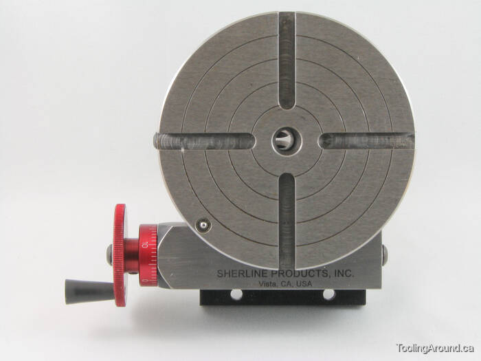
Most small rotary tables have some sort of center hole, sometimes with a cylindrical bore but often with a Morse taper. If the part you"re wanting to center has its own center hole, you might be able to make a plug that fits the rotary table center hole and the part center hole.
The more common way of centering a workpiece on a rotary table requires that you measure the difference between workpiece radii that are 180 degrees apart, and then adjust the workpiece location on the rotary table to split the difference. The most common tool used to make the measurements is a dial gage or dial indicator that must be held stationary; most often the dial gage is anchored to the machine spindle while the rotary table base is clamped to the table.
After you center the work on the rotary table by eye, set a dial indicator up to probe the reference surface. Adjust the indicator holder or move the table so that the dial gage plunger is pressed about half way into its range of travel before zeroing the indicator. Now turn the rotary table top and workpiece (as an assembly) a half turn before reading the dial gage.
Now you want to move the workpiece relative to the rotary table surface until the dial gage reads one-half of the second value. Let"s say your two dial gage readings are A. 0.000 inch, and B. 0.138 inch . . . you want to move the workpiece until the dial gage reads 0.069 inch at BOTH positions A and B.
Next, you need to repeat the measure-rotate 1/2 turn-measure-split the difference process at positions C and D, which must be on a line perpendicular to that connecting A and B.
Since it"s about impossible to move the part on the table exactly the right amount in the right direction, it"s vital that you recheck and readjust A and B after you adjust along C and D . . . and then you"ll need to check and readjust C and D again, and so on and so on. While you"re learning, it"ll seem like you"re chasing your tail, but it is a skill you"ll learn.
To reiterate, the important part is that when adjusting the part on the table you need to rotate the part and table together when you make your measurements, NOT the machine table.
Then later, if you need to center the table under the spindle, you rotate the spindle to measure and move the machine table, which has the rotary table and part bolted to it, to make the adjustment.

G234 Tool Center Point Control (TCPC) lets a machine correctly run a contouring 4- or 5-axis program when the workpiece is not located in the exact location specified by the CAM-generated program. This eliminates the need to repost a program from the CAM system when the programmed and the actual workpiece locations are different.
G234 Tool Center Point Control (TCPC) is a software feature in the Haas CNC control that allows a machine to correctly run a contouring 4- or 5-axis program when the workpiece is not located in the exact location specified by a CAM-generated program.
This eliminates the need to repost a program from the CAM system when the programmed and the actual workpiece locations are different. The Haas CNC control combines the known centers of rotation for the rotary axes (MRZP) and the location of the workpiece (e.g., active work offset G54) into a coordinate system.
TCPC makes sure that this coordinate system remains fixed relative to the table; when the rotary axes rotate, the linear coordinate system rotates with them. Like any other work setup, the workpiece must have a work offset applied to it. This tells the Haas CNC control where the workpiece is located on the machine table.
TCPC is activated with G234. G234cancels the previous H-code. An H-code must therefore be placed on the same block as G234. G234is canceled by G49, G42, and G44.
TCPC G-code is programmed from the tool tip. The control knows the centers of rotation for the rotary axes (MRZP), the location of the workpiece (active work offset), and the tool length offset. The control uses this data to calculate the position of tool tip relative to the active work offset and maintains a static tool tip position through rotary feed moves.
G234 Tool Center Point Control (TCPC) is a software feature in the Haas CNC control that allows a machine to correctly run a contouring 4- or 5-axis program when the workpiece is not located in the exact location specified by a CAM-generated program. This eliminates the need to repost a program from the CAM system when the programmed and the actual workpiece locations are different.
The Haas CNC control combines the known centers of rotation for the rotary table (MRZP) and the location of the workpiece (e.g., active work offset G54) into a coordinate system. TCPC makes sure that this coordinate system remains fixed relative to the table; when the rotary axes rotate, the linear coordinate system rotates with them. Like any other work setup, the workpiece must have a work offset applied to it. This tells the Haas CNC control where the workpiece is located on the machine table.
For clarity, the illustrations in this section do not depict workholding. Also, as conceptual, representative drawings, they are not to scale and may not depict the exact axis motion described in the text.
The straight line edge highlighted in is defined by point (X0, Y0, Z0) and point (X0, Y-1., Z0). Movement along the Y Axis is all that is required for the machine to create this edge. The location of the workpiece is defined by work offset G54.Location of Workpiece Defined by G54
TCPC is invoked in . The Haas CNC control knows the centers of rotation for the rotary table (MRZP), and the location of the workpiece (active work offset G54). This data is used to produce the desired machine motion from the original CAM-generated program. The machine follows an interpolated X-Y-Z path to create this edge, even though the program simply commands a single-axis move along the Y Axis.G234 (TCPC) On and the B and C Axes Rotated
Invoking G234 (TCPC) rotates the work envelope. If the position is close to the travel limits, the rotation can put the current work position outside of travel limits and cause an over travel alarm. To solve this, command the machine to the center of the work offset (or near the center of the table on a UMC), and then invoke G234 (TCPC).

“The Australian Government (Commonwealth of Australia) selected French company Naval Group to deliver a fleet of 12 regionally superior submarines, to be known as the Attack Class, for the Royal Australian Navy. The Attack class fleet will be built in a modern submarine construction yard in Osborne, South Australia.
The Future Submarine Program will deliver Australia a capability that can be built, operated and maintained autonomously, which maximizes opportunities for Australian industry throughout all phases of the program.
As the design of the Attack Class progresses, Naval Group works in cooperation with its suppliers that now includes the Starrag Group. Dr. Marcus Queins, Manager for the Large Parts Machining Systems business unit at Starrag, explained, “We are proud to be involved in this prestigious project in Australia.” Starrag has been selected to supply a Droop+Rein G 110TT HR100 C vertical gantry machine that is capable of handling both large hull elements and high-precision components for submarine construction. With traversing paths of 45.93″ x 42.65″ x 11.48″ in the XYZ axes and a 3′ turntable, the gantry will be the largest machine tool ever put into service in Australia, according to Starrag.
Starrag is collaborating with the Australian machine tool manufacturer H&H Machine Tools Australia to deliver this critical equipment. H&H will manufacture key components, supply qualified personnel to help install the gantry and provide technical support for the entire life cycle of the machine, securing an ongoing role in servicing and maintenance in the future. Starrag will provide H&H with the necessary expertise through onsite training and quality control, transferring critical skills and autonomous ability to Australian industry.
“The contract was awarded following a complex selection process. The Starrag Group was selected due to its many years of experience and its extensive technical expertise in handling large, complicated projects,” said the spokesperson. “Few machine suppliers can manage an order of this magnitude from over 19,320 miles away, but this was not a problem for the Starrag Group since H&H will facilitate local work, ensuring that everything runs smoothly onsite. A previous project carried out in South Australia, for which Starrag supplied four machines for aircraft construction, demonstrates a proven track record in this regard.”
“The size and efficiency of the milling machine being supplied, which is also capable of turning components due to the integrated rotary table-tried and tested as part of the Dörries range of lathes from the Starrag Group-was of fundamental importance,” continued the spokesperson. “The Droop+Rein G 110 TT HR100 C owes its high precision to features such as the hydrostatic guides in all linear axes, as well as the thermo-symmetrical design of the milling unit with its integrated C-axis.”
Milling heads can be changed automatically via a head change interface. The team responsible selected five different machining heads to use on this project. The high-performance fork milling head features not only the ability to use the tool at any angle but also the necessary prerequisites for heavy-duty machining on five axes simultaneously. Alternatively, the machine can be used with one straight and one angled 100 kW (134 HP) milling head with a torque of 7,500 Nm (5531 ft-lbs.). A turret and a horizontal facing head are available for turning operations on the components.
The operator can reach any point on the workpiece due to the spacious cabin, which travels along the gantry and features the latest Siemens operator panel. The cabin can reach a height of 8 m (26′) and be moved towards the center of the table.
With proper maintenance, the machine will be operational for the entire duration of the submarine project. The first of the Attack Class submarines will be delivered in the early 2030s and continue into the early 2050s.”

The versatile 900 series direct drive rotary tables are particularly suitable for HSC milling, mill-turn machining, modern hobbing (power skiving) or even demanding grinding operations. This transforms a simple and cost-effective 3-axis milling center into a fully automatable, multi-functional 5-axis machine. The housing of the 900 DD series is fully sealed to IP 67 and even rotations of well over 2,000 rpm are no problem. A specially developed Fail Safe system brakes the spindle to 0 within a very short time (e.g. With an emergency stop or power failure) without damaging the rotary table.
A wide range of accessories and clamping options are available for the standardized front and rear interface. The sophisticated clamping cartridge concept ensures that the workpieces remain clamped even if no power is supplied. This means that the high safety requirements of international standards are met in the best possible way.

KURAKI has as many Horizontal Boring & Milling Machine models to fit our customers’ needs. Here are some points to assist in selecting the optimal machine for your requirement.
The main spindle of the KURAKI Horizontal Boring & Milling Machine is a feeding type with a spindle diameter 110 mm, 130 mm, or 150 mm. Normally, the larger the spindle diameter, the stronger the twisting rigidity becomes for heavy-duty cutting. For machining soft materials like aluminum, a high-speed quill spindle is recommended.
Confirm that the workpiece to be machined matches the machine table size (worktable size) and workpiece allowable mass. Select a bigger size than expected, not an exact size for the workpiece, so that the optimal machine performance can be performed.
Axis travels vary depending on the workpiece machining positions and the machining widths. The larger the W-axis (Quill travel), the deeper the machine can cut. The larger the X-axis and Y-axis values become, the wider and higher the workpiece can be.
The standard rotary tables of the KBT series can rotate 360° at every 0.001° both right and left by NC for high-accuracy indexing. In addition to the multi-face machining effectively completed by only one setup, Continuous rotary milling during table rotations is possible in addition to one-setup multi-face machining.
Corresponds to machining of heavy-duty and long workpieces by eliminating the rotary function and widening the table width. Effective continuous machining is also available by one setup of multiple same-shape workpieces on a table.
A sub table at each side of the rotary table for long or multiple workpieces is designed to locate at a position lower than the rotary table not to interfere with a workpiece. Each table can have a different workpiece on it. Moreover, the use of a dedicated fixture (parallel block) can better hold a long workpiece when machining.
Use of multiple pallets can allow other workpieces to be used to setup multiple pallets for increased productivity. After machining, the pallets are automatically changed, increasing unmanned operation and improving energy efficiency and productivity. More pallets equal longer unmanned operation of the machine.
One-face machiningMulti-face machiningTilted-face machiningRotary millingLong workpieceSetup efficiencyContinuous machining of multiple workpiecesUnmanned operation

This website is using a security service to protect itself from online attacks. The action you just performed triggered the security solution. There are several actions that could trigger this block including submitting a certain word or phrase, a SQL command or malformed data.

Many metalworking products do contain metals that are included in the latest Prop 65 warning. Exposure to the elements can be harmful. May cause cancer and reproductive harm.
Indexing Heads for 8 inches to 12 inches Phase II Horizontal Rotary Tables. Phase II Indexing heads or Dividing Plates (241-101) allow you to precisely divide a circle into a number of divisions or degrees. The indexing feature helps prevent errors during the repetitive adjustments required in indexing work. The dividing plate set is used to divide one 360° table rotation into divisions of 30". The gear ratio of the compatible horizontal rotary table is 1:90. This means that 90 rotations of the handwheel rotate table one full rotation. This model of dividing plate accessories is compatible with Phase II horizontal rotary tables of size 8 inches, 10 inches and 12 inches. Therefore for one full rotation of the table, the number of handwheel rotations per division "N" times the number of divisions "T" is equal to 90 rotations of the handwheel. So N x T= 90 or N = 90 ÷ T. Say for example, if 17 divisions are required for indexing on a workpiece, then T=21, so N= 90/17 =55/17 = 5 10/34. With 5 full handwheel rotations, 17 divisions are covered and the rest 10/34 by one handwheel rotation. The 10/34 of a handwheel rotation is obtained by using the dividing plates. The annular holes as provided in the dividing plates permit the required number of divisions of one handwheel rotation. The weight of the dividing plate is about 5 lbs.
Our online store is your easy one-stop source for all things metalworking, and we’re positive we can help you find the perfect quality solutions for all your machine shop needs.
For assistance with finding the right tools or any other questions, please feel free to call our customer support team at 800-221-0270 or use our chat feature now.

It"s a while since I"ve done this but as far as I remember, for the circular piece the process is the same as centering in a four jaw chuck - treating the rotating table as a chuck. I suppose it depends on your clamping mechanism as to how easy this is. A hinged DTI holder so you can lift the DTI out of the way and then drop it back in precisely the same position helps.
Another method is to turn a plug to go into the central hole of the table which then locates in in a hole bored in the workpiece but it"s not always possible to do this and you need to get a good fit for accuracy.
If you can mark the centre of rotation on the workpiece with at least a good centre punch, you could use a dead centre between the point in the punch hole and and another centre or similar in the mill chuck and put the DTI on that.


 8613371530291