
cutting gears with a rotary table factory

SteveEx30 cutting the teeth in plastic goes pretty quick,probably a couple hrs.I got 3 gears out of that blank after the teeth were cut.That Nyloil MDX was a pain in the ass to part off.You nave to use plenty of coolant.The stringers will not chip and make a much stronger stringer than Delrin.If you stop before you part off completely it wraps tightly in the groove and takes a while to pull out before you proceed.I have found,with plastic and brass that when cutting multiple gears that it is quicker to cut the teeth first first then part off the blanks.It is easier to finish the blanks and then cut the teeth but you have to make a more complicated mandril and have to change blanks one at a time.I was able to stay on cutting the teeth to completion,but had to wait a day after I set up before I could start,then several days before I could finish because of breakdowns,other priorities.So it is hard to figure exact time but maybe 3 hrs per gear.Since these types of jobs are added value of my own initiative the time factor is not as critical as it would be in a job shop with a customer waiting.One good thing about this place is that I am allowed to tackle any job that I think I can do.I am 70 years old and when I think about retiring,my hobby would be dicking around in my shop doing basically the same thing as I do at work,without the insurance,pay and benefits!

Gotta keep track of those partial degrees and add them up and move the dial accurately. One mistake in your math or turning the knob and you have scrap.

The handle can be removed easily by releasing the caphead bolt. The handle being located with a keyway. This then allows the dividing plates and crank to be fitted in place of the free-rotating handle.
The crank handle is held in place with a grub screw – ensure this is tight and that the handle and pin are at 90° to the crank plate before trying to fit the crank to the table.
12 divisions is achieved with 7.5 turns – so 7 complete turns of the handle and then with a 20 division plate the dividers are set at 10 + 1 holes apart.
his takes a bit of concentration to use as you count off the rotations and then add the part rotation needed for the division – just be consistent and all will be fine.
A very small 12 tooth gear made with a cutter designed for a larger number of teeth and hence the undercut on the teeth – the wall is rather thin at the centre, but this was a trial to see how the rotary table works when being used as a divider – aim is to make more gears for my Wood and Metal Clock.
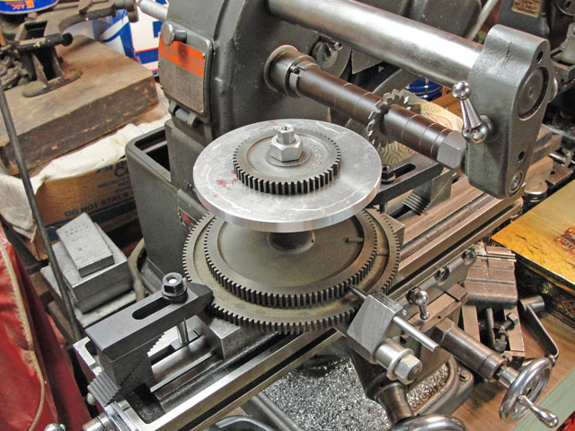
A pair of gears cut together out of mild steel – 60 teeth and 43mm diameter. One of these is for the camshaft side of a four-stroke engine in construction.
I created a quick google spreadsheet (below) that gives me divisions up to 200 and for completeness the first row gives 360 divisions. I have added a link to a downloadable pdf version if that helps. Note: number of hole intervals means you need to count the hole that the pin is in as 0 and then count out the number of intervals/steps from there (next step being 1).
A freely available spreadsheet that has the full dividing plate and rotary table calculations. You can set it up for your specific table and print off the sheets. You just need to know the worm drive ratio.

Small spur gears would usually be made with a dividing head . As the diameter of the gear gets larger the limit is set by the center height of the dividing head.
The next option is to tilt the dividing head into the vertical position. By now the rigidity of the sytsem is not very good. The solution to this is to arrange some sort of support to the gear being cut at the point where it is being cut.
An alternative to using the dividing head is to use the rotary table in the horizontal position. The workpiece is mounted with spacers on the rotary table. The milling table is raised so the workpiece is at about the same height as the cutter on the horizontal arbor. Each cut is made by raising the milling table so the cutter cut the full width of the face of each tooth.
with a vertical milling machine the simplest way of holding the cutter is by using a stub arbor. If a dividing head was being used the easiest arrangement is for it to lie along the axis of the milling table. In this case the cutter has to be in front of the workpiece or behind it.. The maximum diameter is limited by the distance between the axis of the dividing head and the axis of the stub arbor – not very much.
The alternative is to use a rotary table mounted vertically. The most obvious way is for the axis of the rotary table to be at right angles to the milling table. In this case the cutter cuts the gear at its side. A variation on this is to tilt the vertical head so the cutter is above the top of the gear being cut.
In the example above the diameter of the workpiece is probably larger than the largest diameter that will fit on any lathe likely to be available. But it is quite possible to turn it on the milling machine.

Cut gears with your rotary table by using dividing plates (index plates) to get the exact divisions. You can also precisely divide a circle into a number of divisions or degrees, cut bolt hole circles, or mill polygons with the use of these dividing plates. 33-101 is a 3-piece set that fits on your 6" rotary table, 33-100. 33-106 is a 2-piece set that fits on your 8" rotary table, 33-105.

Apple pi made essentially 16 of these for our swerve modules this year. In the offseason, we started by cutting the piece to the correct shape out of an aluminum tube on the lathe, then we used a rotary table on a Bridgeport to drill the smaller holes. What we ended up doing during build season was make them out of a block of aluminum that we cut on a circular saw then faced on a Bridgeport. Then that piece went in a Haas mini mill where all of the cuts were made and then was cleaned up on a lathe.
With what you have I would recommend either doing the lathe then rotary table option or do all the main cuts on the lathe and then use the cnc router to do the smaller holes.
If it is possible for the cnc to make the whole thing, then I would start with a block of aluminum cut to the right height and then just put that in vice in the mill. You can leave the bottom part a square, but do virtually every other cut/hole, and then put it in the lathe and make the bottom circular.

It swivels so you can set it up so the face is horizontal but by the time you add a chuck it"s getting quite high and you sometimes run out of room for the tooling.
I have used it in the vertical position to cut a 107 tooth gear which isn"t covered by any of the dividing head wheels I"ve got. I set up an excel spreadsheet with the angle required for each tooth which isn"t as easy as it sounds as the rotary table is calibrated in degrees/minutes/seconds rather than decimal degrees so it took a bit of figuring out how to do it.
Anyway, I cut the gear all right (crossing out each angle on the spreadsheet as each tooth was cut) but you really need to be concentrating using this method.
One problem I had with the BS-0 is that the tapered hole isn"t a #2 Morse taper but a Brown and Sharp taper which meant I couldn"t find any collets for it. In the end I made a 1/2" collet out of brass which I found to be really useful. I don"t know if that is the case with the modern versions.

Shunmugam M, Narayana S, Jayapraksh V (1998) Establishing gear tooth surface geometry and normal deviation: part 1—cylindrical gears. J Mech Mach Theory 33(5):517–524
Shunmugam M, Rao B, Jayaprakash V (1998) Establishing gear tooth surface geometry and normal deviation: part 2—bevel gears. J Mech Mach Theory 33(5):525–534
Litvin F, Kim D (1997) Generation and simulation of meshing of modified involute spur gears with localized bearing contact and reduced level of transmission errors. ASME J Mech Des 119:96–100
Umeyama M (1995) Effects of tooth surface modifications on the transmission error of a helical gear pair and its opimization. Trans Jpn Soc Mech Eng C 61(582):8–15
Suh S, Lee E, Kim H (2002) Geometric error measurement of spiral bevel gears using a virtual gear model for STEP-NC. Int J Mach Tools Manuf 42:335–342

To me, this table is just the right size and weight, not so small as to be a mere toy, but not too large, heavy, and expensive for my simple needs. I have had it for three weeks now and decided to review it after completing my first project.
When I first examined it I noticed that is seemed very well made and operated very smoothly. It definitely exceeded my expectations. I noticed it had a backlash of 20 minutes of arc, which I considered this totally acceptable. Accurate work is always done by turning knobs in one direction only. This table has a convenient knob to hold the position when it is reached. You can set the angle to about 1 minute of arc, and hold it there.
For my first project I made a couple of simple fixtures. One was a centering hold down, the other was an aluminum sub base. This is especially useful for mounting the table vertically in my drill press cross vise.
The project itself was a 2" diameter hub to mount an 8" sanding disc to a 1/2" shaft. The hub has 6 holes that I wanted to lay out precisely. Three holes run through the rim for set screws to hold the shaft. Three holes through the face attach the disc to the hub. Pictures of the hub and fixtures are attached.
Automatic rotary tables have a large range of applications, for example, in manufacturing or inspection stages of sophisticated components in the aerospace, automotive, and other scientific industries. When it comes to automatic rotary tables, they are tables that are motorized and equipped with a CNC system.
A rotary table is an accessory that performs high precision positioning for a variety of metalworking applications. Widely used in advanced machining, the operators can perform drilling, milling, cutting, and other jobs at exact intervals on the axes in a horizontal or vertical structure. To achieve a high level of accuracy and efficiency, many operators install index plates or dividing plates to work with the basic rotary tables. With the help of these accessories, the rotary tables can be more versatile for indexing applications and enhance precision when machining by positioning the materials at divisions on the dividing plates.
Rotary tables are more widely mounted flat with the rotations around the vertical axis. The arrangement is the same as the structure of working planes and milling cutters in the vertical type of milling machine. In another setup, the rotary table is mounted on a 90° angle plate and the rotation will be performed on the horizontal axis. The tailstock can be utilized to grip the workpiece between centers. Rotary tables can be used in a wide range of applications, such as machining spanner flats, cutting straight, arcs, curves, circular pieces, drilling holes, milling helix, and so on. By adding a compound table or X-Y table on the rotary table, the operators can adjust the center freely, allowing cutting to perform at any desired position on the surfaces.
Automatic rotary tables, or CNC rotary tables, have a large range of applications, for example, in the manufacturing or inspection stages of sophisticated components in the aerospace, automotive, and other scientific industries. When it comes to automatic rotary tables, they are tables that are motorized and equipped with a CNC system. Automatic rotary tables are also preferred devices widely applied in CNC machining centers to act as the fourth axis since they can precisely locate the parts with different angles, helping the machine tools to perform multiple face machining at one time
In a normal machining center that has 3 axes, the three linear axes include X, Y, Z-axis. The Z-axis is the one aligned with the main axis of the 3-axis machining centers. While the X-axis works in the vertical direction, the Y-axis represents the horizontal working direction. The rotary table can replace the fourth axis in machining centers which is the rotational axis 180° around the linear lathe axis. With a CNC motor, the automatic rotary tables can increase the flexibility of metalworking applications without additional human supervision. For example, this configuration that involves an automatic rotary table machining center can be applied to helical grooves producing, blade machining, and more.
The core components of an automatic rotary table include the supporting disc where the metal pieces are clamped during cutting, a solid base which is the connecting element to another larger table, or machines like a drill press and milling machines, the CNC motor. The table disc acts as the spinning surface on which the workpieces are positioned and clamped. The chuck can grip the workpieces, and the dial indicator can be helpful when checking if the chuck and pieces are centered. After mounting the chuck with bolts, critically calibrating and locating the jobs on the table, the disc is ready for rotation under the control of the CNC motor. The indexing plate or dividing plate can be added in most types of disc. When the CNC controller and the CNC motor provide inputs, the rotation of the worm gear is activated and the mating gear mounted beneath the table surface begins to spin, either. The worm gears perform the precise rotations of the rotary table and every part of the disc are critically calibrated in degrees.
The motors in an automatic rotary table can determine the router"s precision and overall efficiency. The two classes of CNC motors used in automatic rotary tables are the stepper motors and the servo motors. Differences between servo motors and stepper motors lie in the overall pole count. Servo motors have a lower pole count (from 4 to 12) than stepper motors (between 50 and 100).
Stepper motors work with a consistent pulse providing ideal drive control and high torque at low speeds. Compared to servo motors, the stepper type is also inexpensive and widely available. However, they generate considerable vibrations and higher amounts of heat, which might lead to failure in some applications. Servo motors need the encoder to regulate pulses for precision positioning. The main advantage of servo motors is they can provide high torque even at high speed and stepper motors cannot. They do not create vibration or resonance problems and maintain at approximately 80% efficiency.

Press "Memory" key (usually [M] or [M+]) to store (Remember that the first calculation is actually for the second cut, because the first cut is made with the handwheels both set at "0".)

This page describes an application of the Sherline Rotary Indexer for clock wheel (gear) cutting. The tool will be used by Ray Bates, a clockmaker in Newfane, Vermont. The mounting was designed and fabricated by Pete Warren in Keene, New Hampshire. They have mounted the rotary table to the quick change gear plate of a South Bend lathe. The rotary motion is coupled to the lathe with an insert in the back end of the headstock. Every motion of the rotary table is transferred to the headstock. The gear cutting tool will be mounted in a milling attachment of the cross slide. A remote trigger switch will be plugged into the Interface connector of the rotary table controller. This switch will be mounted to the bed of the lathe. After each tooth is cut by advancing the the cross slide into the wheel blank, the cross slide will be backed out and run into the switch, which will automatically index the headstock to the next tooth position. In this way clock gears with any tooth count can be cut by simply changing the division count of the CNC rotary indexer.
A refinement of this procedure will shortly be possible which will automate the entire wheel cutting operation. We are now adding a "daisy chain" function to the rotary table controller. A second stepper motor and controller could be mounted to the lead screw of the lathe. This motor would be configured to advance the wheel cutter into the wheel blank and then retract it. The feed rate can be set to slow speeds for cutting steel pinions, or faster feeds for cutting brass wheels. Each time the lead screw motor advances and retracts the cutter, it will trigger the indexing motor to rotate to the next tooth position, which will trigger the lead screw to advance the cutter again. Once this setup is adjusted and started, it will cut each tooth of the wheel one after another without further action by the operator.
Though it is common for clockmakers to cut gears on a lathe, a similar operation could be set up with the CNC rotary table and a Sherline milling machine. With two controllers and a stepper motor mounted to the X axis of the milling machine, completely automated cutting of gears can be achieved.
Shown here is the CNC Rotary Indexer mounted to the back end of the South Bend lathe. Note the solid aluminum mounting plate which is bolted to the quick change gear plate of the lathe. The red handwheel allows the operator to hand crank the rotary indexer during setup. The rotary table can be locked with an Allen wrench in the screw on the front-facing side of the table, above and to the left of the stepper motor.

A:Generally Suppliers of the Slotting machines are providing only one year warranty period in the lathe machine. And it is not the proper return according to your investment. While We are providing 3 years warranty in our products. If there any parts damaged in your machine than we also provides free parts service in warranty period by fastest courier service.
A : Auto feed, Electric Motor, Vertical attachment, Rack cutting attachment, slotting attachment, dividing head, coolant pump with fittings, true chuck, Milling Adaptor, face mill cutter, milling vice, milling collet etc.
A: Yes, accept domestic LC for 60 days on credit. Generally our 75 % customers are purchasing Machine from us with 60 days Credit through a Simple Process of LC. When the Seller is Unknown or New to the Buyer, Letter of Credit is one good Alternative to do the Business with Such New Seller Because Buyer can Avoid Risk by such Letter. Letter of Credit is one Additional Benefit to the Buyer by which they canprotect Loss against Goods and Finance Also.The buyer can build safeguardsinto the letter of credit, including inspection of the goods and quality control, and set production and delivery times.


 8613371530291