
cutting gears with a rotary table in stock

SteveEx30 cutting the teeth in plastic goes pretty quick,probably a couple hrs.I got 3 gears out of that blank after the teeth were cut.That Nyloil MDX was a pain in the ass to part off.You nave to use plenty of coolant.The stringers will not chip and make a much stronger stringer than Delrin.If you stop before you part off completely it wraps tightly in the groove and takes a while to pull out before you proceed.I have found,with plastic and brass that when cutting multiple gears that it is quicker to cut the teeth first first then part off the blanks.It is easier to finish the blanks and then cut the teeth but you have to make a more complicated mandril and have to change blanks one at a time.I was able to stay on cutting the teeth to completion,but had to wait a day after I set up before I could start,then several days before I could finish because of breakdowns,other priorities.So it is hard to figure exact time but maybe 3 hrs per gear.Since these types of jobs are added value of my own initiative the time factor is not as critical as it would be in a job shop with a customer waiting.One good thing about this place is that I am allowed to tackle any job that I think I can do.I am 70 years old and when I think about retiring,my hobby would be dicking around in my shop doing basically the same thing as I do at work,without the insurance,pay and benefits!

I have an 8" Rutland horizontal/vertical RT made in Taiwan that is about all I want to carry around without mechanical help. It has done all I ask of it, and a larger fixture plate mounted to the top of the table could be up to any diameter I care to make it. It is a high quality RT, and I am happy with it. Just went out and weighed it on a bathroom scale, said ~55 pounds. I also recently picked up a beautiful old adjustable height tailstock for it. It is also very heavy and solid, maybe 25 pounds.
I also have a 6" swing dividing head (no maker"s mark, WWII?) with two sets of three dividing plates, two D.E. Whiton 1-3/4" 8 tpi mount chucks (3 and 4 jaw, also marked Rivett!}, and #9 B&S spindle tooling for it as well, and a mill mounting table adapter plate that holds the dividing head and the tailstock to it for quick mounting to the mill table. Throw it on the mill, tighten 4 bolts, and it is ready to use, with less than .001" tolerance fit everywhere.
Given the choice between dividing head and rotary table, I vote for both! The jobs they do are mostly quite different, and one does not work for the other very well. In a pinch, yes, it can be done.

I am in the process of recentering everything starting from the rotary table and every piece attached. I may not know where the actual error was located if I correct it while reinstalling everything. I think that the removable jaw on the chuck may not have been fully seated. The other suspect is the collet block. Lots of places for error. While going through this I am getting into things like cleaning the chuck. There are chips in the chuck and things are binding. The gear blank has a 1" dia hub so that is a better place to hold on to it than with the 3/8 bore. The table has a MT2 hole but it is difficult to mount to that because the blank must be extended out away from whatever holds it to provide clearance for the cutter. I am concerned about trying to hold a 2 1/2" dia piece by the 3/8 bore. My previous method of making the gear in the spin indexer has a lot fewer places for error but I just got the dividing plates and wanted to try that method. I made 9 gears for this project using the spin indexer and they all work just fine except that this one gear. I used a piece of oil impregnated brass that I had but it was too soft and stripped the teeth.

I have used Aloris Posts and tool holders for 45 years , but do not know what you mean about "quick threading attachment" --is that where the gear is ?
The handle can be removed easily by releasing the caphead bolt. The handle being located with a keyway. This then allows the dividing plates and crank to be fitted in place of the free-rotating handle.
The crank handle is held in place with a grub screw – ensure this is tight and that the handle and pin are at 90° to the crank plate before trying to fit the crank to the table.
12 divisions is achieved with 7.5 turns – so 7 complete turns of the handle and then with a 20 division plate the dividers are set at 10 + 1 holes apart.
his takes a bit of concentration to use as you count off the rotations and then add the part rotation needed for the division – just be consistent and all will be fine.
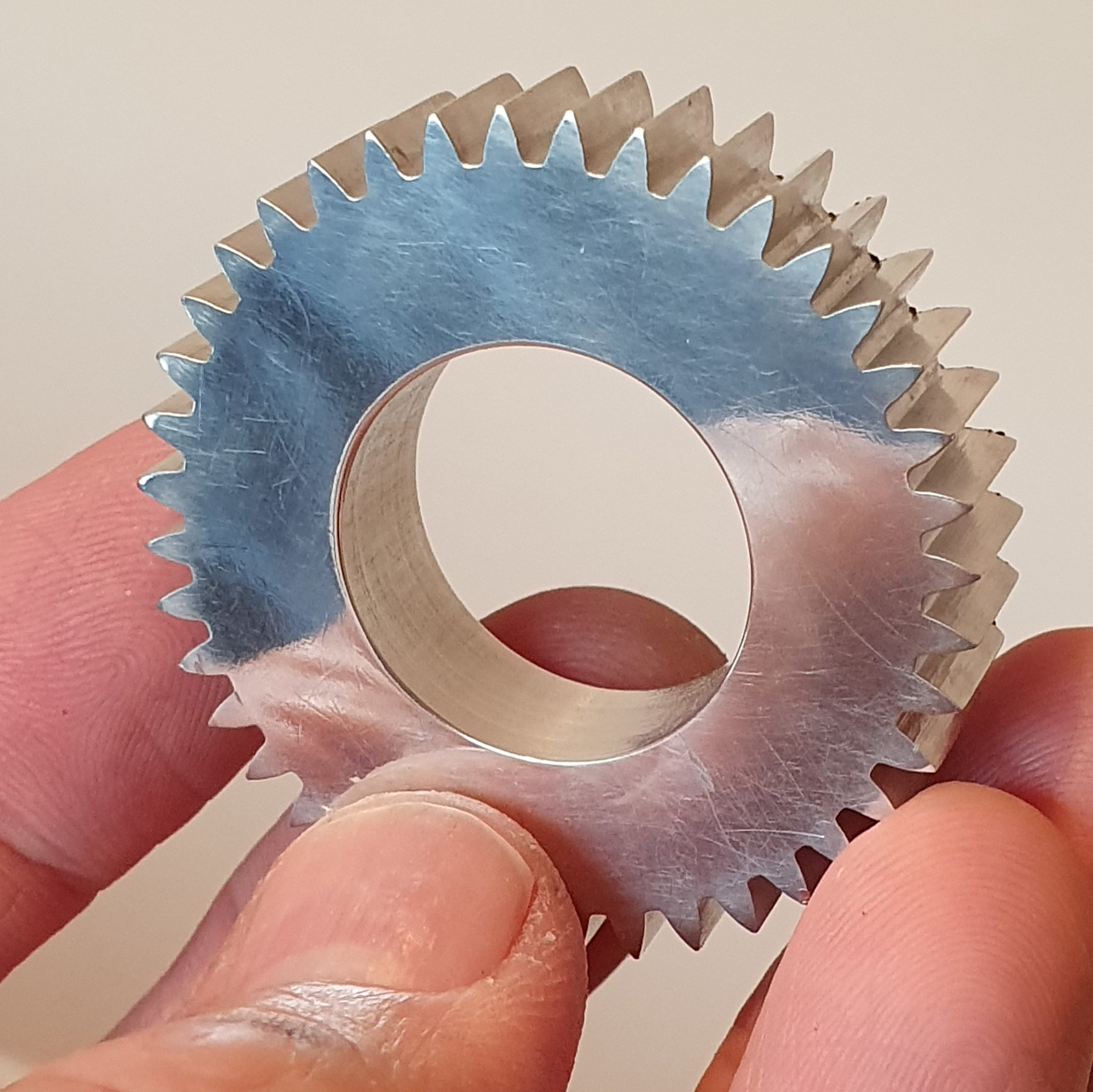
A very small 12 tooth gear made with a cutter designed for a larger number of teeth and hence the undercut on the teeth – the wall is rather thin at the centre, but this was a trial to see how the rotary table works when being used as a divider – aim is to make more gears for my Wood and Metal Clock.
A pair of gears cut together out of mild steel – 60 teeth and 43mm diameter. One of these is for the camshaft side of a four-stroke engine in construction.
I created a quick google spreadsheet (below) that gives me divisions up to 200 and for completeness the first row gives 360 divisions. I have added a link to a downloadable pdf version if that helps. Note: number of hole intervals means you need to count the hole that the pin is in as 0 and then count out the number of intervals/steps from there (next step being 1).
A freely available spreadsheet that has the full dividing plate and rotary table calculations. You can set it up for your specific table and print off the sheets. You just need to know the worm drive ratio.

CNC Indexing & Feeding Technologies is proud to represent the TJR line of rotary tables, indexers and accessories. TJR originated as a rotary table sales and service agent and established itself as an OEM in 2009.
TJR tables feature an anti-wearing worm gear, durable, high-tensile brass shafts, and braking systems with a large clamping range. All new TJR tables come standard with a 3-year parts warranty.
Standard Rotary Tables. The AR Series is TJR’s standard 4th axis pneumatic brake rotary table. It is offered in both a Right hand motor mounting and Left hand motor mounting option. The HR Series is TJR’s standard hydraulic brake 4th axis rotary table.
CNC Indexing & Feeding Technologies offers a wide range of TJR rotary tables. However, many are unclear about what rotary tables can do for their business, as well as how they work in CNC machining. First, let’s consider the basics about a rotary table and how it works in the machining and manufacturing processes.
Milling and other industrial processes require cutting and shaping, usually with a high degree of precision. This creates the need for computer-guided systems that can create workpieces, prototypes or tools for companies on demand. The process is expedited, reducing or removing the need for large assembly line staff or other hand crafters.
In many cases, the work pieces created through CNC machining would be impossible without computer assistance. The code used to communicate between the CNC machine and computer software is specialized. Older machines, or manual machines, used hard wired controllers. However, new CNC machines rely on modern devices like CDs, USB drives, networks and so on.
A lathe or milling machine requires its own set of parts to work sufficiently. For example, an indexing head is needed to allow circular shaping. The indexing element allows the piece to be rotated at an angle or even divided into sections.
A rotary table can tilt and rotate. The table makes use of the indexing head in order to cut according to a specific technique. This makes it possible for the machine to create a workpiece with complete flexibility in rotation and angling.
A rotary table can help to create arcs and circles, an important process in part or tool fabrication. Tools can be specially made, such as car parts, machine parts, and many other objects.
The CNC process lets companies make straight cuts even with multiple angles and to cut small objects into even smaller parts. CNC rotary tables can also help in the processes of cutting gears, drilling or cutting holes.
The table can also be used along with a dividing head and index plate, to further concentrate the shaping. Tables are also used to hold certain parts for superior milling techniques.
Adding rotary tables will improve your capacity to produce the parts you want and increase profits. This brings us to the primary advantage of CNC rotary tables: less time and greater accuracy in cutting.
Companies are often outsourced to create work pieces for larger brands. However, some companies simply create their own prototypes, tools or work pieces with their own facility for machining. There are also contract shops, mechanic shops, electronics companies, inventors, engineering, and retail companies.
Most companies save costs by scaling their needs with small productions. In many cases, they may only have one facility or work with one type of part. The key is not to create “anything” but to specialize in objects created so the process can be streamlined.
The benefits of using cnc rotary tables include consistency, faster production and increased capacity. Products and work pieces assembled through CNC systems are more reliable than products created manually or through other methods. The process is identical each and every time, so consistency can be guaranteed. This is critical for a company trying to ensure safety protocol.
Flexibility is another advantage, as the systems are programmable. These systems are designed to minimize downtime in between their running processes, offering greater flexibility.
The capacity of complexity of product is another benefit. Complex motions are made simpler by CNC rotary tables, making them more affordable to produce.
Naturally, such an intricate process cannot be unsupervised, since efficiency depends on optimal performance. A supervisor must oversee a rotary table operating with CNC controls to ensure the machine and software are configured correctly.
This involves setting the system up, installing the software, and watching over the production. If something goes wrong, the software must be fixed and the machine repaired. Machines are not constantly running, but must be evaluated and cleaned regularly, ensuring that they will be mostly self-sufficient.
We offer a wide variety of rotary tables to meet all of your needs. This includes standard rotary tables with full rotating axis capabilities, and vertical and horizontal mounting positions.
We also offer large rotary tables with hydraulic brake systems, which allow higher clamping torques. You can also find assistance with smaller rear mount rotary tables or tilt rotary tables.
Horizontal rotary tables are specially made for horizontal mounting and carrying a much heavier weight. Horizontal index tables are available, whether in manual or CNC index tables style. Finally, there are face gear rotary tables and rotary table accessories, ideal for projects that need higher degrees of accuracy.
Remember that quality production is synonymous with efficiency and accuracy. Product producers must have the right equipment operating at full capacity in order to guarantee consistency.
CNC Indexing & Feeding Technologies can help you find the machine tool accessories you need to meet your production demands. This includes simple rotating feature, larger work pieces, vertical and horizontal applications, or even 4 or 5 axis work. With TJR rotary tables, you can improve your cycle and process time, reduce your down time and increase your profits.
You can always reach us if you have additional questions regarding how to get started by calling us at 513.770.4200. It’s time to expand your business and your capability!

This is the most versatile rotary available- not only works in horizontal and vertical positions, but any angle in between allowing milling of complex angles on your parts. The table is 4.3" in diameter and has a 90-1 ratio on the handwheel. The handwheel is a 60 tooth drive pulley allowing the easy bolt on addition of our CNC drive kits. Made from the finest fine grain castings and precision ground for accuracy.
There is a 360 degree scale around the perimeter of the main table with a metal pointer. The worm drive is on an eccentric and can be adjusted for minimum lash and continually over the life of the product, as well as the ability to rotate out of mesh so the table can be rotated freely by hand.
Included is a 3" diameter 3 jaw scroll chuck which can be adapted easily to the rotary table either with an adaptor plate as shown in the photo or by drilling and tapping the table to accept the 3 mounting bolts.

This plate can be used either directly, or through a geared dividing mechanism. In direct indexing the workpiece and plate rotate in a 1-to-1 ratio, and holes are used directly. That is, a plate with 12 holes can divide the workpiece into 2, 3, 4, 6, or 12 equal segments. A dividing head incorporates an internal gear ratio (usually 40:1, 60:1, or 90:1) with the same plates. In doing so, the dividing head enables many more combinations than just direct indexing.
For example, imagine a plate with 15 equally-spaced holes and a dividing head with a 40:1 gear reduction. In direct indexing, a workpiece could be divided into 3, 5, or 15 equal segments. Using the dividing head, the same workpiece could be divided into 2, 3, 4, 5, 6, 8, 10, 12, 15, 20, 25, 30, 40, 50, 60, 75, 100, 120, 150, 200, 300, or 600 segments. Essentially, the dividing head acts as if it’s a direct indexer with 600 holes; 15 holes in the actual plate * 40:1 gear ratio. Let’s look at how some of these combinations are possible.


 8613371530291