
diy 4th axis rotary table brands

Tombstones correspond to Fixture Plates on a mill. There are many different shapes and sizes of Tombstones available for 4th Axes. Here’s one I’ve shown before from a big horizontal milling setup:
I was reading an article about Tombstones in the Tormach blog recently and it got me to thinking about how Tombstones on VMC’s can make a job more profitable.
Tombstones are par for the course on Horizontal Machine Centers, but they’re seen a lot less often on Vertical Machining Centers. Perhaps it’s because they’re just built into a lot of HMC’s at the factory whereas you have to set one up using a 4th Axis on the a VMC. The question for this article is how to get a handle on their value?
There’s an old saying that you’re not getting the most return out of your CNC Machine until you have fixtured a job up so that every square inch of the table’s accessible area is being used to make parts. Put as many parts as possible down for each setup, in other words. Relying on just a single machining vise, for example, can mean a lot of available table area is wasted versus putting two vises on the table (so you get 2 parts per setup), or two double station vises (so you get 4 parts per setup). It’s all about how many parts the machine can “chew” on for each setup. The more the merrier because your setup time divided among all the parts will invariably be less on a per part basis.
Now consider a tombstone like the one pictured above. It’s like having 4 smaller tables available. In fact the width of the tombstone is 4″and the length is 13″, so counting all 4 sides, you get 4 x 4 x 13 = 208 square inches. That’s actually 22% more area than the travels suggest would be available on the table. So, for about every 4 parts we can fit 1 part gets a free ride. That’s not bad!
In addition, we can machine 3 faces on each part. Ordinarily, that would take 3 setups which would be a lot more time consuming. Pretty cool, eh? Depending on how much additional setup time is required for this arrangement versus just using the table, we’ve probably made our job more profitable. Perhaps by quite a bit.
Suppose we had a tombstone that was a full 18″ long to match the Tormach’s travel. Yes, we might need a big fixture plate so the 4th axis and tailstock have room on the table, but that’s doable. With the same math, we’d get 4″ x 18″ x 4 sides = 288 square inches. Dang, now we’ve got 68% more available area and we’re really starting to cook with fire. 68% more parts each time we press the green button get finished.
Suppose we create our own “Tombstone” with a piece of 1″ thick cast iron. We can go 2″ if we want it to be more rigid. Now, let’s further assume it is the width of the table’s diameter, which for the 8″ 4th axis is 7.9″. We’ll mount it dead center of the axis, make it a full 18″ long, and use the two sides. Our total area is now 7.9 inches x 18 inches x 2 sides = 284 square inches. That’s almost as good as the earlier tombstone example, and gives us 66% more area.
What if we have a triangular tombstone that just fits in the inscribed circle of the table? No problem. The math says each of the 3 faces of the triangular tombstone will be 6.84 inches, so we have 6.84 x 18 x 3 = 369 sq inches. That’s 116% more area than on our table–twice as many parts per run. Winner, winner, chicken dinner!
When you look at it this way, it’s not hard to see how a 4th axis with tombstone can increase the available area for parts in each setup and make available more faces of the part to be machined.
For round parts, and for many things that go ’round, lathe tooling is where its at. After all, it’s optimized to do workholding along a rotating axis. Hence, it’s very common to mount lathe chucks on your 4th Axis:
All the same ideas that apply to which chuck to use in a lathe work for 4th Axes on mills. Years ago, I put together a chart that has been useful to me in turning work and we can refer to it here too:
“Repeatability” applies to the ease with which you can remove a part and put it right back into the chuck in exactly the same position so you can continue machining. It’s a big factor to consider, but typically isn’t as important for 4th Axis work as it is for turning. When turning, for example, you often have to swap a part end for end, or you may have to take an existing part and put it in the lathe to rework some aspect. With a 4th Axis, you will often just stick in a piece of raw material, in which case Repeatability is not a factor. Hence the ubiquity of the relatively non-repeatable 3-jaw chuck for 4th Axis work.
Turning between centers happens fairly often with a 4th Axis just because you have to make sure you’re supporting any part with significant overhang out at the end too. How much is significant? I was taught 3 or 4 diameters was about a much as you want to hang off the chuck on a lathe before you start looking for more support.
Collets are really nice for turning work (hence the ubiquity of the old Hardinge Lathes and their 5C collet system). They get high marks on just about every aspect. It’s no coincidence that the original Haas 4th Axis had a 5C indexer:
I never would have guessed it, but Geof on CNCZone says the following 4-axis mill set up was able to machine these aluminum bars to length, ensure the faces were square, and drill and tap a hole faster than he could do it in a lathe. You can imagine each of those 4 parts being a 5C spin indexer and suddenly you fit quite a few more parts on your 4th Axis.
I’ve written at more length on Stallion’s Trunnion fixtures in another post. They’re very slick, but you need to make sure they solve the problem you need solved for your 4th Axis. In particular, the access to the part is going to be limited to the access you can get form a vise. As such, you’d be looking to use a Vise on your 4th Axis largely because it is super easy, familiar, and to gain access to 3 sides of the work rather than just the top in a single setup.
Workholding and Fixturing are always an art that it pays to learn well. I’m always on the lookup for clever setups and fixtures and you should be too. The 4th Axis opens whole new avenues for fixturing and setup.

About 3 years ago I bought a cheap rotary table that I converted by taking off the handle and replacing with stepper motor. I used thrust bearings and whatever I could think of to minimize the backlash but it was a big FAIL. The internal worm gear mechanism was so sloppy that backlash was measured in degrees. Its been sitting on the shelf collecting dust. Since then I found out about Harmonic Drives and what high end CNC/Robotic systems use for rotational axis. A new harmonic drive is big $$$$ so eBay to the rescue. The gear head I used is planetary but made by Harmonic Drive Systems so it is very precise. It’s simple and just the right size for my small cnc. Since the stepper motor, gecko drive and gearhead was bought off eBay, it wasn’t that expensive. Under $150. I had upgraded my mini lathe to a bigger 5″ 3 jaw chuck. The 3″ chuck wasn’t being used anymore so I put it on the gearhead.

Small Milling Machine CNC Control system: $18,385M400 3 axis with 1Kw AC Brushless Yaskawa servo motors and drivesMedium Milling Machine CNC control system: $22,175M400 3 axis with 2Kw AC Brushless Yaskawa servo motors and drivesLarge Milling Machine CNC Control system: $25,760M400 3 axis with 4.4Kw AC Brushless Yaskawa servo motors and drives
Small Slant Bed Lathe CNC control system: $15,450T400 2 axis with 1Kw AC Brushless Yaskawa servo motors and drivesMedium Slant Bed Lathe CNC control system: $18,795T400 2 axis with 2.2Kw, 2.2kw w/brake AC Brushless Yaskawa servo motors and drivesLarge Slant Bed or VTL CNC control system: $21,597T400 2 axis with 4.4Kw, 4.4 Kw w brake AC Brushless Yaskawa servo motors and drives
Auto part set, Auto tool set, 3D contouring, 4th and 5th axis machining, Available in OEM configurations, Professional Installation with Service & Training and DIY CNC kits for both new machines and retrofit upgrades.
CENTROID Boss series II retrofit customer testimonial"The quality and workmanship of the CENTROID equipment was outstanding and very professional. CENTROID was able to custom tailor the control to allow us to continue to use our rotary milling arrangement as before and even expanded our capability. The short story is that we ended up with a four axis CNC mill for less than half the cost of the three axis Haas. This includes the work that was done by our staff."
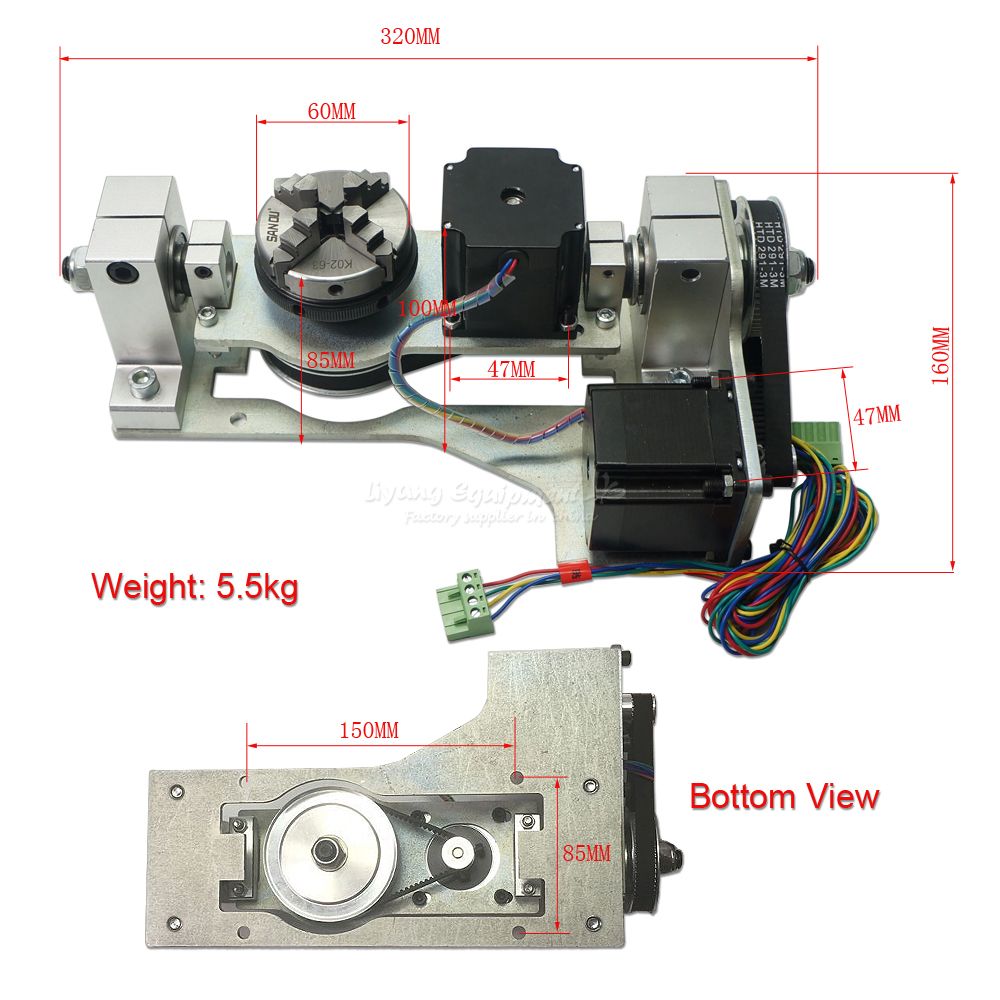
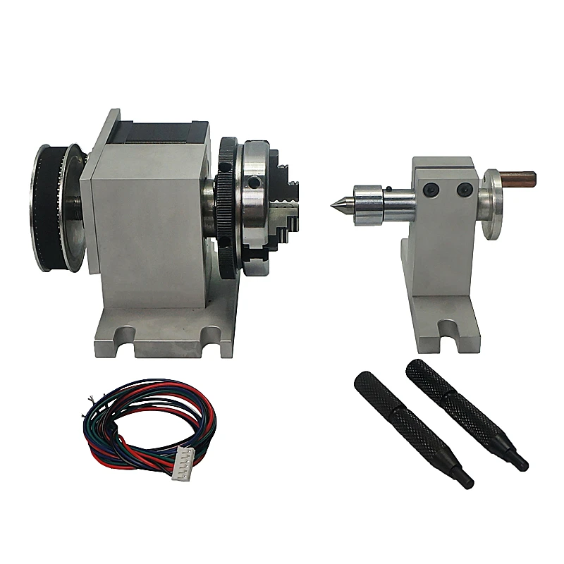
2022 best desktop CNC router with 2x3 4th axis rotary table is an entry level CNC machine kit designed for for craftsman, home shop, hobby, small business, advertising, woodworking, arts, gifts, crafts, sign making, and mold making.
STG6090 desktop CNC router kit is an entry level CNC router machine with 2x3 rotary table for hobbyists, small business, home business, small shop, home shop and craftsman. The rotary 4th axis CNC router table adopts whole cast iron machine bed, cast aluminum gantry with dustproof system, under impact resistance beam more stronger with higher machining precision. The 4th roatry axis CNC router machine adopts high quality ball screw and high accuracy segmentation to achieve the final high precision machining result. It adopts high precision all steel linear guide rail to ensure the machine frame more stability and durability. The desktop CNC router kit adopts high power driver system and stepper motor to drive the machine to run smoothly with higher efficiency. The spindle motor adopt high-speed water frequency conversion brushless motors from domestic famous manufacturer, not only can cut vigorously, but also can carve with higher precision. NCStudio, DSP, and Mach3 CNC controllers are optional with high stability and high efficiency for the desktop CNC router kits, they are easy to learn and use. It has good software compatibility, it is compatible with the Artcam, Type3, Ucancam, JDPaint and other CAD/CAM softwares for 2D/3D routing. The desktop CNC router is equipped with a 4th axis rotary table for 3D carving. It is also known as 4th axis CNC router, rotary axis CNC router, desktop CNC machine, benchtop CNC router, benchtop CNC machine, tabletop CNC machine, tabletop CNC router.
The 4th axis CNC router kit adopts Mach3 or advanced DSP numerical control system and large liquid crystal display brings out much convenient operation and simpler maintenance.
2. The machine adopts water-cooling spindle, suitable for all kinds material (wood, aluminum, copper, stone, plastic and foam ). The water cooling spindle adopts water cycle to cooling the spindle, so the cooling effect is very good, almost no noise and long life time.
4. Guide rail: Taiwan Hiwin square rails (the world famous rail and guide manufacturer), self-lubricating sliding block. This will ensure equal force in all directions and accuracy and strength of the 4th axis CNC router table.
The 4th axis desktop CNC router machine has a wide range of 2D/3D applications for small business, small shop, home business, home shop and craftsman:
The 4th axis desktop CNC router can be used for wood, stone, plastic, acrylic, double color boards, PVC, ABS, aluminum composite panels and other soft metals, etc.
Yes, in order to give you a suitable entry level CNC kit, please tell me the max working area, materials for processing and the thickness for the materials to be cut. Then an affordable CNC router machine will be recommended to fit your requirements.
All the CNC routers can be shipped worldwide by sea, by air or by international express logistics via DHL, FEDEX, UPS. You are welcome to get a free quotation by filling up the form with name, email, detailed address, product and requirements, we will shortly contact you with the full information including the most suitable delivery method (fast, secure, discreet) and freight.
KME CNC Rigid Cast Iron Trunnion Tables are one of the leaders in the industry for accuracy, surface finishes and repeatability. Allowing you to speed up your cycle times, these tables are ideal for high volume production applications. Powerful and compact trunnion design ensures smooth operation over the entire travel range.
It’s true that less than 10% of machined parts require simultaneous 5-axis movement. Which means that more than 90% of the parts machined in a typical job shop would not benefit from expensive, complicated, full 5-axis contouring; but that doesn’t mean your shop wouldn’t benefit from simple, affordable, 5-axis indexing capability. Work platter: Available in 6.75" diameter, T-sloted platters with drilled and tapped holes to accept Raptor or any brand work-holding, vises, fixtures, chucks, etc. Also available in dual-spindle system for increased efficiencies by cutting the number of tool changes in half.
1. QuindexPneumatic 5th Axis Bolt-on kit:Easily bolts-up to your existing true 4th or semi-4th axis rotary table. Shop air drives the spindle 90 degrees up against hard stops as well as provides 300 lbs. of brake force to allow for heavy cuts. A simple M-code or relay closure triggers indexing. This is the most cost-effective option to start 5-sided machining and is designed to mount to most other brands of rotary tables. (As well as ours of course!)
2. Quindex Semi 4th and Pneumatic 5th Axis Package:This package is everything you need to turn your 3-axis machine into a 5-axis workhorse.This package comes completely assembled and mounted on a subplate for a fast, accurate set-ups.
•Index Designs true 4th axis rotary table with Quindex 5th axis head, outboard support all mounted on a subplate. Call or email for quote on your specific machine. Please provide year, machine and control
brand with model number and if machine is 4th axis ready including amplifier. For example: 2015, XYZ machine with Fanuc OiMF control, not 4th axis ready, no amp.
Control digital devices and make machinery more precise with a stepper motor from Alibaba.com"s wholesale equipment store. Our catalogue is the place to come when you need a replacement stepper motor rotary table or any other motor related products. You"ll find a huge array of wholesale motors, including step motors with high torque ratings that can offer incredibly precise control. Whether you"re constructing an astronomical telescope or a digital network for broadcasting, these motors will do the job.
Stepper motors are used in situations where devices need to be calibrated to extremely high levels of precision. They aren"t always the most powerful motors, but they do have very high torque levels, and this allows them to control devices in ways that other motors cannot. And they also tend to work well with digital devices due to their "step" mechanism. For instance, you can find step motors in many hard drives, handling millions of operations every minute. They have also become a go-to motor style for robotics installations. So you might need one for an advanced production line. When you need a stepper motor rotary table, finding the right motor is easy. Just search Alibaba.com"s catalogue and you"ll easily find what"s required.
Our stepper motor collection covers every base. Browse motors for use with mini computers like the Raspberry Pi or models designed for use with Arduino components. Look for permanent magnet motors, variable reluctance steppers, or hybrid syncronous steppers, and models with micro step, half step, and full step modes. Our listings include everything you need to control the most complex systems. So find a stepper motor rotary table and order what you need today. Everything can be handled with a couple of clicks, putting specialist stepper motor components within easy reach.

4ListofFiguresFigure 1. Haas OM-2 (Haas) ........................................................................................................... 9Figure 2. Haas TRT 100 (Haas) .................................................................................................... 10Figure 3. Nikken 5AX-130FA (Nikken) ....................................................................................... 10Figure 4. Anti-Backlash Mechanism Patent Design (Mauro) ....................................................... 11Figure 5. Rotary Table Bearing Patent Design (Bullard) ............................................................. 11Figure 6. Rotary Table Apparatus Patent Design (Kato) .............................................................. 11Figure 7. Manufacturers in Japan use blue ink to machine precision ground gears (Mitzubishi) 12Figure 8. Cone drive manufactured by Cone Drive Solutions (Cone Drive)................................ 12Figure 9. Duplex worm gear drawing provided by Allytech (Allytech)....................................... 12Figure 10. Split gear (Machine Design) ........................................................................................ 12Figure 11. Manually adjusted worm drive .................................................................................... 13Figure 12. Spring loaded spur gears to reduce backlash (Machine Design) ................................. 13Figure 13. SGMJV AC Servo Motor (Yaskawa) .......................................................................... 14Figure 14. Cutting Torque Data .................................................................................................... 15Figure 15. Cutting Force Distribution........................................................................................... 15Figure 16. Velocity Profile for Both Axes (Yaskawa) ................................................................ 16Figure 17. Axis A Motor Performance and Operating Point ........................................................ 16Figure 18. Axis B Motor Performance and Operating Point ........................................................ 17Figure 19. NEMA 23 Stepper Motor ............................................................................................ 19Figure 20. Back to back bearing configuration ............................................................................. 20Figure 21. NSK angular contact bearings ..................................................................................... 20Figure 22. Geometry Configuration, Cantilever-Cantilever and Cantilever-Fixed ...................... 24Figure 23. Cantilever spring forcer ............................................................................................... 25Figure 24. Worm gear backlash reduction system ........................................................................ 25Figure 25. Method to reduce backlash in worm drive .................................................................. 25Figure 26. Tapered Roller Bearings .............................................................................................. 26Figure 27. Thrust bearing .............................................................................................................. 26Figure 28. Gen5 rotary table with motor placement ..................................................................... 26Figure 29. Completed prototype 1 ................................................................................................ 27Figure 30. Rotary Schematic......................................................................................................... 28Figure 31. Gear preload system .................................................................................................... 29Figure 32. Rendering of rotary exploded view ............................................................................. 29Figure 33. Housing Maching Set Up ............................................................................................ 34Figure 34. Housing inspection ...................................................................................................... 34Figure 35. Spindle Machining....................................................................................................... 35Figure 36. Spindle Assembly ........................................................................................................ 36Figure 37. Perpendicularity Measurement .................................................................................... 37Figure 38. Custom stepper motor controller ................................................................................. 38Figure 39. Laboratory setup diagram ............................................................................................ 40Figure 40. Accelerometer mounting configuration on housing with components removed......... 40Figure 41. Housing mounted to the shake table ............................................................................ 40
6ListofTablesTable 1. Comparing Backlash Reduction Options (Machine Design) .......................................... 14Table 2. Axis B SigmaSelect Summary ........................................................................................ 17Table 3. Axis A SigmaSelect Summary ....................................................................................... 18Table 4. Yaskawa Motor Specs .................................................................................................... 19Table 5. Reduced specifications list used for concept generation ................................................ 21Table 6. Morphological matrix used to group solutions for concept generation .......................... 22Table 7. List of chosen concepts from the morphological matrix. ............................................... 22Table 8. Decision Matrix evaluating each concept according to important criteria ..................... 23Table 9. Decision Matrix for Backlash Reduction Methods......................................................... 24Table 10. Factors of Safety for Components ................................................................................ 31Table 11. Complete list of parts and cost for both rotaries ........................................................... 32Table 13. Stackup Chain ............................................................................................................... 33
7Executive SummaryDr. Jose Macedo and Professor Martin Koch of the IME department saw that there was noavailable 5th axis rotaries compatable with smaller CNC machines, and desired one in ordermachine more complex wax patterns for lost wax casting. Commercial 5th axis rotaries typicallycost around 30,000 USD, which is quite an investment for smaller institutions and so oursponsors Koch tasked our team with designing, building, and testing a 5th axis rotary table thatwill match commercial specifications at much lower, aproachable price point. The project beganby researching existing rotaries and developing a list of technical specifications that the designmust satisfy. Using these criteria, a preliminary design was created and initial calculations wereperformed to verify the design. The first prototype was manufactured and after performing a fewtests, changes for improving our next generation design was determined. The design wentthrough a complete overhaul, and a new prototype that was more robust and better designed formanufacturing was machined using CNC machines. Based of testing results, each rotary stagehas a natural frequency of about 400 Hz, which should be avoided when used for machining. A4th axis rotary table using a Haas specific Yaskawa motor was made as well as a complete 5thaxis rotary table. Over the course of the last quarter, the choice of motor changed due to sponsor-related circumstances, and so the resulting 5th axis design was chosen to be driven by two steppermotor and an external controller that works in conjunction with a G-code macro.
81. Introduction1.1 Sponsor BackgroundThe sponsor of this project is Dr. Jose Macedo and Professor MartinKoch of the IME department. Professor Koch often machines waxfor lost wax casting instead of molding the patterns, since the designsare typically unique. He and Dr. Macedo wanted to explore thepossibility of designing and building a 5th axis to machine complexpatterns, but it must fit in his existing Haas Office Mill.
1.2 Formal Project DefinitionThe IME department would like to have five axis simultaneous Figure 1. Haas OM-2 (Haas)machining capabilities to manufacture small wax parts. There aretwo Haas OM-2 vertical machining centers, which are currently available for this project. Due totheir small size, there are no commercial quality 4th and 5th axis rotary tables available in themarket. This team was created in order to design and build a low cost 4th and 5th axis rotarytable for the OM-2.
1.3 ObjectivesCompletion of this project entails the development of a 5th axis rotary table with compatiblefixture connections, appropriate drive cards, and 5th axis CAM software and postprocessor. Thetable must be able to rotate in two axes, while allowing the largest work piece possible. It mustmount to standard T-Slots, and have a platter with a standard bolt pattern sothat commercial fixtures may be attached. Structurally, we are aiming to resist light cuttingforces in wax or plastic under high-speed conditions. Our goal is to match the resolution,accuracy, and repeatability of existing large rotaries in the 25,000 USD price range. This goal isstated with the understanding that commercial systems reach their specifications by havingextremely tight component tolerances, which are typically produced with dedicated machines,and may not be entirely achievable.
1.4 Project ManagementFor this project, while everyone had a part in every step of the process, individuals were assignedto manage certain aspects of the project in order to assure that the project would be completed ontime. The design of the rotary was completed with every team member present. Ricky led theanalysis of crucial components and Nicole was in charge of the mechatronics side of the rotary interms of build and design. Irene managed the scheduling and the timeline to ensure that the teamwas on track for completion. Irene was also the main communicator with the sponsor. When timecame for manufacturing, Dakota lead the manufacturing due to his background with CNCmachines. The vibrations tests were conducted under Ricky and the Mechatronics tests wereconducted under Nicole.
The trend towards smaller CNC machines in industry has lowered the cost of small table size /small taper vertical machining centers to approximately 50,000 USD (Haas). At the same time,advances in CAM software have made programming parts simpler than ever before. Moreconsumer groups, such as high schools, light industry, universities, and dental practices arecapitalizing on the availability of these CNC machine tools.
2.2 Existing ProductsA concurrent trend in industry has been the utilization of 5th axis rotaries. Aftermarket 5th axisrotary tables can be bought for around 30,000 USD and add two additional axes to the threeexisting axes of a CNC machine. This allows parts to be machined more accurately in fewersetups while enabling the manufacturing of more complex parts. In many situations, purchasing a5th axis table can be a profitable business decision (Sherman). However, commercial quality 5thaxis rotary tables are not as available for the smaller machine market. Typical manufacturers of
Figure 2. Haas TRT 100 Figure 3. Nikken 5AX-130FA (Haas) (Nikken)5th axis tables include Lyndex-Nikken, Haas Automation, Tsudakoma, and Matsumoto. Their5th axis tables are not designed for machines with small table sizes, such as the Haas OM-2.Rotaries within the budget of small organizations are oversized and too heavy for smaller CNCmachines. There is a desire for small 5th axis rotary tables for small table sizes and low cuttingforces, which could bridge the gap between hobbyist tables and industrial tables. In the Cal PolyIME 141 lab, Haas OM-2 CNC machines are utilized to make wax shapes for sand casting. Forwax and soft plastic machining, there is a niche for accurate, but small 5th axis rotaries.
Bullards rotary patent uses an external oil port to keep the rotating contact points submerged at all times. This decreases the effects of wear on the rotary over time and minimized maintenance.
The Rotary Table Apparatus is essentially a fourth and fifth axis rotary table. This design focuses on small and light-weight properties.
Anti-Backlash Split GearsAnti-backlash split gears are commercially available gearsystems that are designed for light loads. They eliminatebacklash through a spring loaded second gear that takes upthe slop in the gear train. These gears are more expensivethan standard gears, and are an effective solution for lightloads. Figure 10. Split gear (Machine Design) 12Manually Adjusted Gear MeshManually dialing in a worm drive is common practicefor manual rotary tables. The worm is adjusted via aset screw that brings the worm and gear into eachother. This allows radial locational adjustment tocounteract manufacturing errors. The Anti-BacklashMechanism for a Rotary Stage patent by GeorgeMauro depicts this design and is further described inthe Patent section of this report.
Table 1 shows the three main criteria for backlash reduction options. As with many components,there is a balance between cost and quality that must be analyzed. Each method is suited fordifferent types of applications and used in certain types of systems. In addition, each solution hasdiffering amounts of backlash reduction.
2.4.2 MotorsEach axis must be controlled independently,which requires two motors and a controller.From collaboration with Haas Automation andYaskawa, we were initially advised to chooseamong the Yaskawa SGMJV motor series to becompatible with the Haas controller.Unfortunately, months later, we found out thatthe SGMJV motors are not compatible with the Figure 13. SGMJV AC Servo Motor (Yaskawa)Haas controller. Instead, we were givenproprietary 200-watt motors. The rest of this section includes the design process of sizing aSGMJV motor, which were ultimately not used in this project, but useful in sizing theappropriate NEMA stepper motors and for further advancements on this project.
Assuming six standard deviations, the max cutting force is 80 Newtons. With a 100mm platterdiameter, the torque seen by the gear train is 4Nm for the B axis, and 8Nm for the A axis.
In addition to cutting forces, the table velocity profile must be specified in order to size a motor.The velocity profile below shows the table accelerating to 100 rpm in 0.5 seconds and switchingdirections after a one-hour interval. This is considered our worst-case scenario motor operation.
After determining the operating point, the SigmaSelect program offered by Yaskawa was used tosize the motors. SigmaSelect inputs are applied torque, inertia, speed, efficiency, gear ratio, andvelocity profile. Outputs include motor recommendations and sizing options. The followingtables are inputs and outputs for the SigmaSelect program.
16 Figure 18. Axis B Motor Performance and Operating PointMotor performance charts for axis A and B show the worst-case operating point withincontinuous operation rating. According to SigmaSelect results, the factor of safety in theintermittent range for Axis A is 3.18 and axis B is 3.19.To better summarize inputs and outputs, the tables below summarize results from SigmaSelect. Table 2. Axis B SigmaSelect Summary RotaryAxis,B Category Parameters Units Value ExternalForces CuttingForce N 80 AppliedTorque Nm 4 Geometry TableDiameter m 0.1 CalculatedInertia TotalInertiaatMotor kg*m2 3.45E06 KineticProfile Acceleration sec 0.5 TopSpeed rpm 100 Deceleration sec 0.5 RunTime min 120 Gearing GearEfficiency 0.5 GearReduction 30 Power MinimumPower W 83.8 SigmaSelectResults RequiredTorque Nm 0.272 RequiredSpeed rpm 3000 RequiredPower W 85.5
A SigmaSelect simulation was performed for each axis operating point since inertia and torquevalues are different. Axis A, the tilt axis, requires twice the torque and significantly more inertia. 17 Table 3. Axis A SigmaSelect Summary TiltAxis,A Category Parameters Units Value ExternalForces CuttingForce N 80 AppliedTorque Nm 8 Geometry PartHeight m 0.1 CalculatedInertia TotalInertiaatMotor kg*m2 1.04E04 KineticProfile Acceleration sec 0.5 TopSpeed rpm 100 RunTime min 120 Gearing GearEfficiency 0.5 GearReduction 30 Power MinimumPower W 167.6 SigmaSelectResults RequiredTorque Nm 0.541 RequiredSpeed rpm 3000 RequiredPower W 170.0
It is also important to consider inertial effects on the motor accuracy. As the load inertiaincreases, the motor has more trouble keeping accuracy when positioning. Each motor is ratedfor an acceptable inertia, as shown in the Yaskawa Motor Specs table. Though our predictedinertias are below allowable, it is important to will test for inaccuracies with the closed loopsystem before finalizing the rotary.
18 Table 4. Yaskawa Motor Specs Motors SGMJV01A3A6S SGMJV02A3A6S Torque(Nm) Rated 0.2544 0.5096 Peak 0.888 1.784 Speed(rpm) Rated 3000 3000 Max 6000 6000 Inertia(x104kg*m2) Motor 0.0665 0.259 Allowable 1.33 3.885 BodyDim(mm,kg) Length 82.5 80 Width 40 60 Height 40 60 Weight 0.4 0.9 ShaftDim.(mm) Diameter 8 8 Length 25 25 Electronics Power(W) 100 200 Voltage(V) 200 200 Encoder 20BitAbsolute 20BitAbsolute
Fortunately, we can use our simulation data to source a stepper motor with the appropriate amount of torque. Although stepper motors run much slower than AC servo motors, as long as the torque is sufficient, the rotary will still function. Also, it is important to consider that stepper motors do not have built-inFigure 19. NEMA 23 Stepper Motor encoders, and will not be as accurate as closed-loop systems.
2.4.3 BearingsBearings are critical for our design in terms of minimizing run-out and providing the precisionwe need for our rotary table. Because of this, our rotary table requires bearings specificallydesigned for machine tools. General practice in the machine tool industry is to use two back-to-back angular contact thrust ball bearings.
19 Figure 20. Back to back bearing configurationThe preload between angular contact bearings is achieved by clamping a pair of bearingstogether. Preload increases rigidity, but consequently, it reduces rated speed. Preload alsoeliminates radial and axial play, increases accuracy and helps to prevent ball skid at high-speed.For our application, at a speed of 100 rpm, a large preload is best. For our spindle the NSK7006C Series bearings are applicable for our rotary table. They are also easily accessible forordering.Assembly using NSK bearings require narrow tolerances for fit, and so to dimension the shaftand housing placement of the bearings, we referred to the manufacturers recommendations. Thespecifications for these bearings are located in Appendix D.
3. Design Development3.1 Requirements/SpecificationsAfter meeting with our sponsors, we determined a list of customer requirements.The 5th axis rotary table should:
Work with small Haas CNC machines on light duty machining of wax-type materials at normal production cutting speeds Be capable of meeting or exceeding the speeds and accuracies of commercial 5th axis rotaries in the ~$25,000 price range Include a way to home the 5th axis mechanism Be safe for human operators Incorporate appropriately sized servomotors from Yaskawa
20In addition to the customer requirements, we created a specifications list to incorporateengineering specifications from which we used to start design process. A reduced list ofspecifications used for considering preliminary designs is shown below in Table 5. The fullspecifications list can be seen in Appendix A. The specifications were developed from evaluatingconstraints of the OM2, comparing specifications from existing products, measured loads, andoperating conditions.
Table 5. Reduced specifications list used for concept generation Engineering Number Feature Value Unit Source Compliance Risk 1. Geometry 1.3 Max Work Table Height 4 in OM2 Specs Inspection Medium 1.4 Max Rotary Height 10 in OM2 Specs Inspection Low 1.5B Work Area Diameter 3 in Rotary Comparison Inspection Low 1.6B Max Work Piece Height 3 in Rotary Comparison Inspection Low 2. Kinematics 2.1 Rotational Speed 30 rpm Rotary Comparison Test High 2.2 Tilt Speed 30 rpm Rotary Comparison Test High 3. Forces 3.1 Max Part Weight 5 lbf Rotary Comparison Test Low 3.2A Average Applied Load 18 lbf Spindle Loads Analysis Medium 3.3 Axis A (Tilt) 6 ft-lb Hand Calculation Analysis Medium 3.4 Axis B (Rotary) 3 ft-lb Hand Calculation Analysis Medium 4. Energy AC Motors OM2 4.1 - - Compatible with Haas Test Low Compatible 5. Materials 5.3 Wax machining - - Sponsor Requirement Test Medium 10. Assembly 10.1 Instructions - - Sponsor Requirement Inspection Low 10.2 Compatible with T-slots - - Sponsor Requirement Inspection Low 12. Usage / Operation 12.1 Workholder Bolt Pattern - - Rotary Comparison Inspection Low Sponsor 12.3 Simultaneous machining 5 axes Demand Test Requirement
3.2 Concept GenerationTo begin the ideation process we created a morphological matrix in which solutions weregenerated for each sub-function of our design. These sub functions or sub-components includedthe type of transmission for the 4th and 5th axes, how the work piece was to be mounted, howthe rotary was to be mounted on the table, the bearings used, and the geometry between the 4thand 5th axes.
21 Table 6. Morphological matrix used to group solutions for concept generation Subfunction Solution Work Part Hole Collet Collet Mounting Pattern (Hand tight) (Automatic) 4th Axis Belt Worm Bevel Spur Planetary Direct Drive Transmission 5th Axis Belt Worm Bevel Spur Transmission Bolt Table Mounting Clamps Pattern Bearings Ball Tapered Roller Journal Thrust Needle 4th & 5th axis Inline Swing Arm Trunnion connection
From the morphological matrix, solutions were combined to create hundreds of completeconcepts. In order to produce a more selective list of concepts to choose from, we eliminatedsome solutions from each sub-function if the solution was not feasible, or other solutions seemedto be much better options in terms of performance, manufacturability, and availability. Theoptions in blue are the solutions we decided to use as concepts. We decided not to includebearings in the detailed drawings because the type will be determined by the rest of the design aswell as space constraints. Since a hole pattern and bolt pattern were our only options, theconcepts focused on the decision of the transmission for the 4th and 5th axes and the structurebetween them. From these concepts we chose 11 to draw out in detail, which are listed in Table 7and attached in Appendix B. Two of the chosen concepts were wild card drawings to explorethe pros and cons of concepts that satisfy the criteria but have an unexpected design. Eachdrawing was discussed in terms of how well the design would suit the goal of the project. Weevaluated all of the sketches in terms of the criteria in the table below and rated each sketch avalue of 1 to 4 where a 1 was given if the design was least desirable in fulfilling the criteria and 4was the most.
Table 7. List of chosen concepts from the morphological matrix. Solution 4th Axis 5th Axis Connection 1 Planetary - Belt Trunnion 2 Belt Belt Inline 3 Direct Drive - Worm Swing Arm 4 DABS Swing Arm 5 DASS Trunnion 6 Spur - Worm Inline 7 Worm - Belt Trunnion 8 Worm - Worm Trunnion 9 Worm - Worm Inline 10 Worm - Worm Swing Arm 11 Belt - Worm Swing Arm
22 Table 8. Decision Matrix evaluating each concept according to important criteria Solution # Criteria 1 2 3 4 5 6 7 8 9 10 11 Minimal Workpiece Height 1 1 4 2 4 3 1 4 3 4 4 Minimal Backlash 1 4 3 4 3 2 3 3 3 3 3 High Rigidity 3 1 3 2 3 2 3 4 3 3 2 Minimal Weight 1 4 1 1 2 3 2 2 4 4 4 High Efficiency 2 4 2 4 2 1 2 1 1 1 2 High Manufacturability 3 3 4 1 2 3 3 2 3 3 3
3.3 Initial Design Considerations3.3.1 Support DesignThe design of a modern rotary table is a complex task, typically limited to large corporationswith decades of experience in the matter. We will design a single rotary stage that could bemanufactured twice and joined to yield a full 5th axis table. The primary engineering features thatpreceded our design and how they apply to the design of our first prototype follows.
StructureThe structure of the machine tool is of primary importance. We do not expect our table to yield,but our design is stiffness limited, with cutting forces causing deflection and making loss ofaccuracy our primary concern. It is also important to stay above the natural frequency of ourapplied loads by ensuring the structure is stiff enough, and counteract any harmonics with adamped design.
Two materials most suitable for this application are cast iron and epoxy-granite composite. Castiron has a yearlong settling time after casting, and as such is unacceptable for our timeline.Epoxy granite is a composite material consisting of granite and quartz particles in an epoxymatrix, and has one of the highest damping factors for any material. Its downside is its lowstrength, which we have considered improving by coming up with a new epoxy-granite-fibermatrix wherein we add carbon or glass chopped fibers to the mix to improve stiffness andstrength. This will be investigated in the future, due to the large R&D required to manufacturesuch a material. We are designing around 6061-T6 AL due to availability and comparablestiffness to epoxy granite.
23 The geometry of our housing was determined to be double-cantilever as shown in Figure 22. This is beneficial because it allows us to design one rotary for both the A and B axes. The major elements of the housing are that it must hold tapered roller bearings, a preload mechanism, a worm drive, and a circular bore for a platter. It is a uni-body design, with the entire structure to be machined out of aluminum.
AntiBacklashDesign We evaluated anti-backlash methods on a numerical basis, where a score of 1 is the lowest score and 4 is the highest score. Table 9 shows our decision matrix results. Table 9. Decision Matrix for Backlash Reduction Methods
Figure 25. Method to reduce backlash in worm drive 25BearingsThe bearings in our design are critical given the high loads that we expect to experience. Thisproblem is further complicated by the fact that cost is a major issue. We designed ourpreliminary rotary housing to use Timken tapered roller bearings. These SET45 Timken bearingsare readily available at auto parts stores, and the runout on several can be inspected beforepurchase, allowing us to use low runout bearing through the laws of averages.
Prototype1DesignThe end result of this is a rotary platform that is both low cost and highly accurate. For the PDRwe purchased a NEMA 23 stepper and motor controller to evaluate the geartrain efficiency andrun tests before comitting to a servo from Yaskawa. This is because friction factors are hard topredict, and empirical data is always more accurate. After we complete a functioning prototype,we will be able to iterate our design and properly pick a motor. Figure 28 shows images of ourrotary table design.
We manufactured a single rotary as described above and have completed testing on it. Bothduring the manufacturing process and during testing we determined some design changes that
26would need to be made for this rotary to be completely functional. We had noticed that aftermanipulating the rotary that the worm wheel was not meshing with the worm gear. The shoulderbolt used for shaft was not rigid enough to maintain straightness and runout. Many of thedimensions and fits needed to be reconsidered for assembly as well. The cavity for the gear wasinaccessable for assembly and the gear itself appeared to be too small to move the rotary. Weused this knowledge to create a design for our second prototype, which we will be described onthe following section.
27 Figure 30. Rotary Schematic4.2.1 CapThe cap holds the outer race of bearing in place and provides the preload in conjunction with thebearing locknut. It also has grooves for O-rings to prevent contaminants from entering the rotary.Half of the reed switch used for homing is contained in the cap. The cap was manufactured usinga Haas CNC Mill.
4.2.2 HousingThe housing is to be manufactured from aluminum. It was redesigned to accommodate our newinternal configuration. There are different configurations for the B axis and the A axis. Thefeatures on both stages are nearly identical with the only difference being that the A axis hasmore material on the bottom of the stage to lift the B axis higher to prevent it from crashing intothe table. The housing was manufactured using a Haas CNC Mill.
4.2.6 Worm WheelThe worm wheel is an off-the-shelf part that was modified for our rotary. A conical countersinkis machined into the worm wheel to perfectly contact the spindle and for proper concentricalignment. This design allows the operator to easily replace the worm wheel for another whenworn out.
4.3.3 InertiaEach Yaskawa AC servo motor is specified with an allowable inertia value that will allow foracceptable motor response. If inertia values exceed those specified by the manufacturer, themotor will not be accurate in positioning the rotary. This code calculates the inertia due to theplatter, motor, housing, drive shaft, worm gear, and coupling as seen by each axis motorseparately. Inertia values for each axis is relatively low due to the 30:1 reflected inertia ratio andgive a factor of safety of 3.73 against response error.
4.3.4 Worm Gear A and BThis code evaluates the worm gear for 25000 hours of life using the AGMA method. It isassumed that the worm will outlast the gear by a large margin due to material properties. In aneffort to share parts between the rotaries, each axis will use a 16 diametral pitch worm and gear.As these gears are critical to the function of our design, the factor of safety against fatigue failureover 25000 hours is 2.80 and 5.04 for axes A and B respectively.
4.3.5 BearingsIt is important that our bearings are rated to the expected loads on the rotary. The most criticalparameter is the spacing between the bearings and their ability hold an applied moment. To savespace in the rotary, two NSK precision bearings are preloaded without a spacer. Without aspacer, the bearings are still capable of the expected loads with a minimum factor of safety of6.6.
4.3.6 BoltsThe code analyzes the bolts that attaches axis B to axis A. There are two sets of bolts to evaluate:the bolts that attach axis B to the fixture plate, and the bolts that attach the fixture plate and axisB to axis A. The largest stress the bolts will see is shear stress. -20 Grade 1 Bolts were usedfor the analysis, resulting in a safety factor of 90.63 for the bolts that attach to axis B and a safety 30factor of 45.32 for the bolts that attach to axis A. The minimum length of engagement for thethreads of the bolts is 0.2856 inches.
Table 10. Factors of Safety for Components Part Longevity FactorofSafety Reference AxisBGear 25000hrs 5.04 AGMAMethod AxisAGear 25000hrs 2.80 AGMAMethod DriveShaft EnduranceLimit 2.98 MarinFactors DrivenShaft EnduranceLimit 20.67 MarinFactors AxisABoltFixture StaticLoading 45.32 Shear AxisBBoltFixture StaticLoading 90.63 Shear AxisBBearings StaticLoading 15.4 BearingLoadRating AxisBBearings StaticLoading 85.56 AxialRating AxisABearings StaticLoading 6.6 BearingLoadRating AxisABearings StaticLoading 40.53 AxialRating
4.4 Cost AnalysisWe have analyzed the cost of both rotaries in a worst case scenario, as shown in the table below.The cost of the 5th axis that we are building for our sponsor will be much lower, as we are gettingthe motors donated from Yaskawa and the bearings at a lower price on eBay. If this were to bemanufactured by someone else, they could research other sources to buy quality parts at areduced cost. If this were to be mass produced, costs would also be reduced by purchasing inmass quantities.
31 Table 11. Complete list of parts and cost for both rotaries CostAnalysis Part/Material Qty Supplier Supplier# Cost Steel 1 IMEDept N/A Aluminum 1 McMaster 290.00 0.25"x0.5"DowelPins 6 McMaster 97395A475 10.21 3/16"x1.25"DowelPins 4 McMaster 97395474 11.25 BallNoseSpringPlunger 2 McMaster 3408A75 7.24 1032x0.5"SocketHeadCapScrews 13 McMaster 92185A989 4.26 1032x0.75"SocketHeadCapScrews 24 McMaster 96006A693 5.71 GasketMaterialNeoprene 2 McMaster 8837K112 21.70 75mmx3mmwideOring 4 McMaster 9262K409 6.26 19/16"BearingLockNut 2 McMaster 6343K160 14.44 3mmSetScrew 2 McMaster 92015A101 9.34 1/4"Shaft 2 McMaster 1144K11 24.15 1/4"IDWasher 2 McMaster 98019A360 6.75 3/4"x.75CapScrew 2 McMaster 90201A111 9.62 SmallBallBearing 2 McMaster 57155K388 9.56 14mmBallbearing 2 McMaster 2423K24 38.22 1/4"20SocketHeadbolts 8 McMaster 90128A242 9.09 1/4"8mmShaftCoupling 1 McMaster 2764K123 60.54 1/4"14mmShaftCoupling 1 McMaster 2764K322 78.69 7006CNSKBearings 4 McMaster 2385K46 1,091.00 SPDT150VDCReedSwitch 2 McMaster 6585K22 92.22 30T16DPGear 2 BostonGear G1043 91.60 16DPWorm 2 BostonGear LVHB1 46.40 200WMotor+Cable 1 Yaskawa SGMJV02A 550.00 100WMotor+Cable 1 Yaskawa SGMJV01A 500.00
5. Product Realization5.1 ManufacturingThe nature of the rotary table requires a very high level of precision, typically beyond the levelswe would be able to achieve in a school setting without precision scraping. This is due to the factthat our system design features a long tolerance chain from the machine table to the rotating Baxis. This chain, as it were, is composed of a number of different machined or groundcomponents which must be maintained within very tight tolerances because their affect onsystem accuracy is compounded greatly throughout the project.
System Tolerance Stackup ChainTolerance Feature Moment Arm Material ToleranceHousing A Perpendicularity of bottom 175mm 6061AL 2 micronssurface to bearing boreBearing set A outer race to inner race 27.5mm Tool Steel 2.5 micronsparallelismSpindle A perpendicularity of datum 10mm Steel 5 micronssurface to center axisPlatter A parallelism from top to bottom 12.6mm Steel 2.5 micronsplaneAdaptor plate perpendicularity from A to B 100mm 6061AL 20 micronsmounting planeHousing B Perpendicularity of bottom 100mm 6061AL 2 micronssurface to bearing boreBearing set B outer race to inner race 27.5mm Tool Steel 2.5 micronsparallelismSpindle B perpendicularity of datum 10mm Steel 5 micronssurface to center axisPlatter B parallelism from top to bottom 12.6mm Steel 2.5 micronsplaneSummation 44 microns
The above table illustrates the fact that even with incredible precision beyond 99 percent of mostmachine shops in the world, the total tolerance stackup is over 44 microns, which frankly isunacceptable for a rotary table. In order to remedy this situation, we used unique machiningtechniques to achieve high levels of precision in only our critical dimensions, and individuallymatched parts to hit our tolerances. This was time consuming and took hundreds of hours.
Figure 34. Housing inspection 34The most critical surfaces we machined were arguably the housing. It is an incredibly complexsystem and arguably making one of these would be worthy of a senior project in itself. Theprecision, fit and finish of the component are astounding. To maintain perpendicularity of thebore to the bottom surface, both of these were machined in the same machine tool, using thesame endmill, in the same operation, with no less than 5 unique finishing passes.
5.2 Design EditsOur planned design described previously in this report was to use Yaskawa servomotors inconjunction with the 4th and 5th axis drive cards from Haas, both of which were donated for ourproject. In order for the motor to interface with the 4th and 5th axis driver cards, we were sent theexact servo motors that Haas uses on their rotaries. Because of this, the motors were much largerand heavier than what we had been planned for and so they could not be used with our design.This was determined very late in our project, so our sponsor requested that we manufacture just afourth axis that is compatible with Yaskawas donated motor.
In order to complete the project that our sponsors originally asked for, we decided to create acomplete 5th axis that was run with stepper motors and an external controller. A G-code macrowas written that calculates the position of each axis and outputs them through the serial line astext. This text line is sent to the microprocessor of our controller, an Arduino Uno, which parsesthe string into recognizable commands and variables. If the letter H is sent, each axis is homed,by spinning until the reed switch registers and then moving to a predetermined offset. Otherwise,each axis can be sent a direction and number of degrees and the Arduino will calculate howmany steps to turn the stepper to move to the new angle.
37Pictured below is the controller, which contains two AC to DC power supplies, a 24 Volt one forthe motors, and a 12V one to power the Arduino. Pololu DRV8825 stepper drivers are used tosend commands to the steppers. A MAX3223 breakout from Sparkfun is used to convert theRS232 input to TTL so that the Arduino can properly receive the text. We chose to use NEMA23 stepper motors with 179 oz. in. of torque in order to withstand machining loads and maneuverthe weight of the B-axis.
5.3 Recommendations for Future ManufacturingWhile we have gone through three prototypes during our senior project in order to refine thedesign and improve manufacturing, there are still a few changes to make in terms of machiningthese parts. Dimensions that have fits should be machined to nominal sizing, and then reamed forfit. Most features should be designed for a slip fit rather than an interference fit if the mating isnot crucial, as it will eliminate the need to risk the part during pressing. If the feature is crucial,machine undersize, and check the dimension before re-machining to size. The accuracy of ourCNC machines were not up to par for machining tolerances of fixtures and so the dimensions hadto be manually accounted for by the operator. Dimensions should be checked after machiningeach part and before assembly. Also, it is crucial to consider flatness tolerances on the platter ofthe rotary, and so the spindle and the platter should be surface ground before assembly.
6.2 Vibration TestingBackgroundVibration testing uses a sine sweep to find the natural frequency of the rotary. Operating at thenatural frequency of the rotary can cause inaccuracies in machining, and possible structuralfailure.
Equipment Rotary Accelerometer Signal Analyzer Blue Box Charge Amplifier Shake TableProcedure 1. Secure the rotary table to the shake table and attach the accelerometer with a dab of wax, as seen in the set-up figure. 2. Connect the charge amplifier to the accelerometer and channel two of the signal analyzer. 3. Preset the signal analyzer to sine sweep between 10-2000 Hz, where the input is chan


 8613371530291