
diy rotary table for milling machine factory

I was once thinking 2 standard transmission flywheels would make a fixture that you are needing. the bottom fly wheel would be surface side down with no ring gear for a bolt down flange. The top flywheel would be face up with a seriese of tapped hole for hold down capabilitys. Im still pondering on the bearing between the 2. The ring gear on the upper flywheel can be mated with a crank handle to provide rotation.
For a corner fillet weld such as those, it may help if you grind off half of each corner on the slotted plates giving a 45 deg V. This will help to ensure the weld gets good penetration and strength at the same time as allowing you to retain the original edges for alignment.
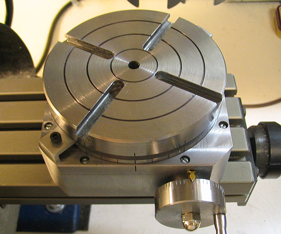
Years ago, before I learned CNC, I owned a Phase II 8″ horizontal/vertical rotary table that I purchased from Kap Pullen’s Getmachinetools.com store. He has them at a good price, BTW, and he’s a darned nice fellow to deal with as well as being a frequent HSM contributor. Anyway, its a nice little table, but I hadn’t done a whole lot with it for quite a while after purchasing it. As is so often the case, one day, a project landed on my doorstep and I was glad to have it.
Before I could get started, however, I had to make some accessories for it. Basically, I needed some T-Nuts to fit the table, as well as a little fixture that makes it easy to hold a plate up off the table through a hole in the center so you can machine it. The latter, what I call a “plate machining fixture”, was inspired by something similar I saw the Widgitmaster of CNCZone fame using to make Dremel clamps for his mini-router:
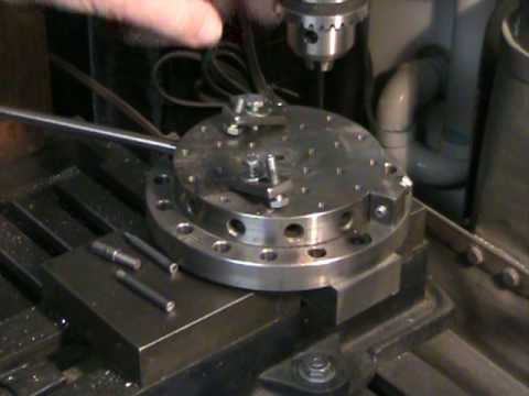
I turned the round spigot using the 4-jaw on the lathe. I’m making the fixture out of MIC-6 aluminum plate, which is pre-ground very flat on the sides. This is a 5 inch by 3 inch piece. I’ve clamped it to the rotab using my T-nuts and the regular mill clamps and step blocks. It is sitting on parallels to make sure I don’t cut into the table. You can also see how I’ve clamped the rotary table to the mill table using a big cast iron V-block I have. You can never have to many blocks with precision faces hanging around!
Having a 4-jaw chuck on your rotary table is mighty handy! Because it’s a 4-jaw, you can dial in the workpiece by adjusting the jaws until it is perfectly concentric with the table’s axis of rotation. The best way is to make an adapter plate that attaches to the back of the chuck in the same way that your lathe does so you can exchange lathe tooling with the rotab. Here is an example:
For the example, the chuck is threaded onto the adaptor plate, and then the holes in the adapter plate’s flange are used to bolt down to T-nuts on the table.
In my case, I bought a 4-jaw from Shars brand new, and simply drilled some through-holes in the chuck to mount to the table directly without an adapter plate:
First, you want to make sure your part is properly centered on the table. To do that, I clamp the table down on the mill table (no special place is needed), put my Indicol indicator holder on the mill spindle, and find some round feature on the part to indicate on. For example, on the plate milling fixture above, indicate on the round boss, or on the center hole. Spin the table and bump the part in until spinning the table doesn’t move the indicator.
Second, locate the center of rotation directly under the mill spindle. You can simply use the X and Y table handwheels to do this. Use that Indicol to indicate off of a circular feature you want centered under the spindle. Turn the indicol around on the spindle and adjust the handwheels until the indicator stays put relative to the spindle position. A Blake Coaxial indicator will make this last even simpler.
When you’re rounding partially by cranking a part around on the rotary table, it’s really easy to go a little too far and screw things up. The answer is to drill the end points to make the exact stopping point on the rotab a lot less sensitive:
Centering with a Blake indicator is really fast, but what if you don’t have a Blake, or worse, what if your mill is too small to accomodate one? Here is a nice solution I found on a German site. This fellow has made an ER collect fixture for his rotary table, and has taken care that when installed on the table, the axis of the collet is aligned with the table’s axis. He can then place a dowel or other straight pin in the collet and line up until it will go into a similarly sized collet on the spindle. Nice trick! It’s similar to how Widgitmaster showed me to align a drill chuck on a QCTP to the lathe centerline with a dowel pin held in the lathe chuck.
This is a re-post of how I built a home-brew rotary table for my mill just over two years ago. Having used it quite extensively, it still works perfectly well for my needs. During the posting, I"ll add some additional comments coloured red in the form of a review; it"s not often one gets to review or re-think a tool or operations after a period of time! I"ll also add a timeline to show how the build progressed.
Some research turned up bits and pieces of information on RTs, and then I hit gold on DeanW"s build of his rotary table - excellently detailed as always by Dean - and the plans available there. Thank you both Dean and Steve
2. An adapter to take any of my Myford chucks and to do machining securely on it. (This adapter gets used very frequently - in fact it is mounted on the RT 90% of the time)
3. Adjustment of backlash on the worm drive - and full disengagement of the drive for "quick indexing" (The backlash adjustment works a treat, though I rarely use full disengagement)
I sourced and scrounged whatever materials I would need for the build; some I had lying around, and a lot I had to buy. I ended up with: Some bits of 10x60mm flat bar and a bit of 12mm plate for the base, a lump of cast iron for the table, phosphor bronze to make the gear out of, an old bit of bolt for some material to make diverse bits, aluminium for the handwheel, a brand new angular contact bearing, a bit of shaft from a printer with 2 small bearings to salvage for mounting the hand wheel shaft, and some 8mm and 16mm silver steel to make the shaft, worm and gear cutter from:
I started on the base; the bit of 12mm plate I had was too big, so I sawed it down in the bandsaw. It was a bit too big for the bandsaw as well; so I started with as much as possible of the plate clamped in the saw vise:
Then I clamped the plate to the mill table with some bits from the clamping kit and supported on two identical bearing outer rings as spacers, and milled three of the four sides square, with the two opposing sides I could get to, to the exact width for the plate (140mm):
Fortunately, I could chuck the plate in the 4-jaw on my lathe; this made it easy to face and bore the hole for the bearing. The corners barely cleared the bed while swinging in the head-gap. :
With the old Myford in medium back gear speed, I started the biggest facing cut I have tried to date. (Back then it was, and still is!) It took a while; very slow infeed at the start with interrupted cuts, and looking at the chips coming off to increase feed rate towards the center. Not a pretty picture, but the "ringy bands" looks worse than they were actually:
Then I bored the hole bigger; (from 19mm to 61.97 mm) I started with a cheapy tungsten carbide tipped boring bar and 20 thou (~0.5mm) depths of cut and things went OK until I tried some bigger cuts. At 40 thou cuts things were going well, but then the carbide tip splintered and everything ground to a halt. Not feeling in the mood to try and re-sharpen the tool, and with the hole big enough for my favourite HSS left-hand(that should be right-hand!) turning tool bit to have adequate clearance, I just plonked that in and finished the cut. I intentionally left a 0.5mm thick ridge about 2mm wide at the back.That was to allow the bearing I have to be pre-loaded without the center of it actually rising up and touching the bottom of the table later on :
A test with the bearing showed that the hole was just about the right size for a press fit for the bearing, but with the plate a bit warm from machining, and the bearing cold, I decided to let everything cool down to the same temperature overnight to make sure of the final fit for the bearing.
First thing that morning, I picked up with the bearing fit, and as I thought, it needed some final sizing. With all the bits at the same temperature, the fit for the bearing would have been too tight, and I ended up taking another 0.02mm (a 0.01mm cut) out of the plate. Then the bearing was a nice hand press fit part-way into it"s hole; the rest will need a bit of tapping with a hammer:
Then I flipped the plate in the chuck - just loosened two adjacent jaws of the chuck, flipped, and tightened down the same jaws, making sure the plate was flush on the chuck teeth with no swarf trapped. There was no need to perfectly re-center it - the last facing was just to get rid of the scale and to make sure the top face was completely parallel with the bottom. As the table will be riding on this surface, I tried to get a better finish - and succeeded:
I just clamped the whole lot together in the mill vise and fly-cut the sides flat. A milling cutter might have been quicker, but once again, the scale on the plates would have made it blunt in short order. I could (and did - twice) re-sharpen the HSS bit I had in the fly-cutter. I also pushed things a bit hard; you can see the blue chips that came off; had me doing a dance while feeding getting hit by those
Then with both the longer pieces one-at-a-time, I squared the bandsawed ends down; one end just square, and then moved to the other end and squared , and then down to the 140mm length needed. After initially squaring the second end, I just measured how far it must be machined down (both plates were about 4mm too long at that point) and went down in 1mm steps on the mill hand wheels with the last step the required fraction of a mm on the hand wheel:
I milled both the "short" sides of the base square and to length. As I"d decided on welding the lower part of the base, I thought it prudent to mil the clamp-down slots in these as well, before welding things together. For milling the 10mm slots, I marked and drilled 8mm holes at the ends:
On the first slot, things didn"t go entirely to plan though... The milling bit easily chewed out the slot with 2.5mm down feeds on each pass. Then I got greedy; and tried a 3.5mm down feed... No problem for the cutter; it worked happily, but left a much rougher finish on the sides of the slot - that seemed to get worse as I went...
By the other end of the slot, I could visibly see the slot was a LOT (~1mm) wider than at the start. I did lock the y-axis on the mill, but it shifted. Note to self! - lock down harder and don"t get greedy. I ended up with an 11mm slot and rough edges. I smoothed both sides of the slot out with some fine milling cuts to look OK - with a very fine climb-milling pass (0.1mm) on each side - fortunately the clamp-down slots are not crucial in size.
Then very carefully shifted the clamped assembly over onto a spare piece of plate to make sure nothing shifted, and put the whole lot down in an open space on the workshop floor for welding together :
I first faced off the one side of the welded base frame in the mill. I made a couple of quick clamping plates from more of the flat bar I used for the base - just saw off and drill an 11mm hole to allow some pivot clearance for a 10mm bolt , and sawed the heads off a couple of 10mm bolts to make shorter clamping studs than are in my clamping kit. The "new" clamping plates was needed as the clamping plates in my clamping kit is too thick for the slots I milled in the base. (Two years later, and these same ad-hoc clamping plates still hold down the RT in use!) T-nuts and the clamping nuts came straight from the clamping kit. I cleaned the mill table VERY thoroughly before clamping down the piece on a bit of paper to prevent it slipping:
Then I flipped it upside down to do the other side. Same process as above - clean and a new piece of paper. With the slots now higher above the table, I needed thicker spacers for the off-set ends for clamping... I settled on using some of the triangular step blocks from the clamping kit; a small one and larger one combined to provide the height. I couldn"t use the flat bar clamp plates as-is on just one triangle block, as it is both a bit soft and too rounded on the ends to ensure a good grip on the step block. I don"t recall ever seeing step blocks used in combination like this to , but it worked a treat
It was a public holiday here in Namibia... I forgot about it... Completely... Imagine my surprise when I pitched up at the bolt & nut store to buy some M5 cap screws for mounting the base plate to the frame
As I would be doing some "interrupted" cuts because the workpiece is not entirely round, and having a skew face, I center drilled it first, and added a revolving center. This was purely a precaution to make sure the workpiece stayed in the chuck if something came loose or jammed up. Some thoughts, a prayer and a thumb-suck made me select high back-gear speed on the lathe for cleaning it up on the circumference. This worked quite well, but my first cut was a bit on the shallow side (0.2mm), and quickly revealed a hard spot in the C.I. skin:
So I re-sharpened the toolbit (that hard spot just flattened it), and took a 0.5mm (0.040") cut to try and get under the hard spot. Instead of using the apron wheel for feeding, I locked the carriage nut, and used the lead screw handwheel for feeding; that gives a finer feed than the apron wheel. This cut came out much better:
First up, I finished facing the piece - with tailstock removed. then I drilled a pilot hole through with a 7mm drill bit - pecking all the way to try and keep the hole as true as possible. The 7mm drill was just long enough for the job:
Then I drilled the pilot hole out to 13mm, and re-sharpened the tip of the carbide tipped boring bar that I broke earlier in the build, and bored the hole to 16mm dead. A test with some 16mm silver steel and I got a light push fit; precisely what I wanted. Then I bored the recess for the mounting flange with light face cuts from the inside to the outside with a HSS toolbit that I ground to a good shape for this type of job on a previous occasion. This is part-way done:
Next I made the needed undercuts on the face. They came out a bit rough on the surface, as I used a threading tool to make them. Fortunately the running faces are nice and smooth - that"s where it matters most for this project. Next up, it was the clamping groove. I did that with a parting tool and the lathe at its absolute lowest speed (back gear low speed). This was still slightly too fast, and I ran into problems with chatter. So I added the tailstock back for some additional support; fortunately my revolving center has a couple of different tips, and I could fit a bigger one to use with the 16mm center hole. This didn"t help a lot though, so at the risk of chipping off the parting tool bit tip, I increased rate of infeed. Fortunately this worked and I soon got into the "groove" with nice chips coming off the parting tool and no chatter. A couple more passes with the parting tool, and I had the groove done:
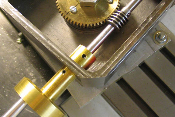
I removed the 4-jaw from the lathe with the table-in-making still mounted on it, and set it aside. The 3-jaw went on, and I started on the main shaft. First off, cut a bit off the big bolt from the first photo in this thread:
Then gripped in the outside jaws of the 3-jaw on the non-threaded part of the bit of bolt, I lightly faced off the end and center drilled it for tailstock support. Then I rough-turned it down to get rid of the threads and then down to 26.5mm - this section will later be turned down to 25mm with some other steps and sizes included:
I flipped the main shaft-in-making in the 3-jaw, and turned the flange section that mounts into the back of the table. The outside of the flange actually becomes a register to keep the shaft concentric with the table, and was turned as accurate as I could for a light push fit into the hole in the table. For some reason I got a poor surface finish; but could not do anything about it. This photo shows the part with the right hand section turned down to "register" size and the end already faced:
I centered the chuck using the table feeds and a bit of that 16mm silver steel in the drill chuck to go into the hole, zeroed the X handwheel and dialled in the 17.5mm offset I needed. Drilled the first hole, loosened the clamp, rotated the chuck against the fixed blocks to maintain position, and indexed with the little square on the same "side" of the next jaw. Clamp down the chuck again, drill & repeat for next hole... QED
Next the holes needed countersinking from the back side... My countersink bit was too big, and waaay to short to reach in there. A broken 8mm drill bit volunteered, and I carefully ground its end to a 90 degree angle with suitable cutting faces. That made countersinking easy, and the holes turned out quite well with no chatter:
The last step, was to punch a witness mark into the flange and the back of the table; these I then "connected" with a scribed line - this will be used to make sure everything can be put back exactly the same at a later stage:
Then I used the punch to mark the table for the screw locations; simple; keep the alignment mark I made aligned; the punch is a close fit in the holes and stands upright by itself in each hole; and a good whack with a hammer on it and each center is marked:
I carefully centered and drilled each hole 4.2mm and 7mm deep on the mill with the chuck clamped to the table. After each hole, I used the drill chuck as a guide to run in the first tap from my M5 tap set. It only left a couple of threads on each hole before bottoming out, but enough to start the 2nd tap outside of the mill on the workbench. Each hole was run down with the second tap till it bottomed. Then the holes were run through with my modified version of an M5 plug tap - it had a pointed tip that I ground down while building "Fred" to really thread some holes to the bottom:
I mounted the 4 jaw with the table/shaft assembly back on the lathe. I know my 3-jaw grips eccentric by about 2 thou - but dead parallel from the chuck to about 100mm away from it - on a 26mm workpiece, and when I tested the shaft on the whole lot as mounted now with a dial indicator, that"s what I got. About 0.05mm eccentricity along the shaft"s entire length, but it was parallel. The outside of the table part as mounted was still spot-on center. So I carefully turned down the shaft part to the needed 25mm for the bearing inner race; it was at 26.5mm so for a first cut I just took off an infeed of 20 thou (that takes _just) over 1mm - off the total diameter). Then I measured the piece to be sure - it was down 25.48mm. I honed the cutting bit in-place on the lathe; just a couple of light touch with the oilstone - then went down to just over size at 25.1mm. A last cut part-way for the last 0.1mm, and I stopped for a test with the bearing and it lightly pressed over - so I finished the cut:
Next I turned the shaft down to 24mm up to a point 15mm away from the base of the table; the bearing is 17mm thick, and with the slight indentation in the table and the offset lip in the bearing mount hole in the base, that leaves me room for threading and run-out to the bottom of the bearing inner race. The 24mm section will be single-point threaded at 1mm pitch for the bearing pre-tensioner nut. I stopped short of the threading; that will take a while, and had better wait for the weekend.
Looking for something more to do, I decided on doing the holes to bolt the base top to the frame. I forgot to mark out the circle the table would run on on the base top plate, and being hit by a sudden sense of aesthetics, I needed to "see" a ring on the base top plate where the table would run. I pressed the bearing in the plate, and fit the whole lot over the shaft and used a permanent marker to mark the outline of the table on the plate:
I stopped there, as while punching the holes, I found my concentration wandering to what I"d have for dinner, and also distracted by the swarfmagnets (dogs) bashing around their stainless food bowls (must have had the same thoughts
First thing, I decided to make the pre-load nut. I removed the 4-jaw chuck (with table in making et al) from the lathe and put back the 3-jaw with outside jaws. Some 50mm aluminium rod was then turned down to just under 40mm for just long enough to make an 8mm wide nut and allow parting off. Then I drilled it out to 19mm for the same depth (19 mm, as it is my biggest drill):
The white liquid is synthetic water soluble oil mixed with water. Normally I would have used methylated spirits on the aluminium, but I ran out. Sometime in the past, I did try this soluble oil on aluminium, but had less-than-satisfactory results on a 20:1 water / oil mixture as recommended for this oil. This is a "new" batch I made up just the other day, and through a fumble, this mix is more like 10:1 - and it worked a treat on the aluminium!
Then I changed back to inside jaws on the chuck, and chucked up the parted off bit of aluminium. It needed to be bored to inside diameter thread size next. I originally intended to thread the nut and shaft M24x1. The change wheels for turning a 40 tpi thread was still mounted from making the Dremel chuck adapter for the mill.
My thoughts went as follows: "I"m lazy to change the gear train. Would this much finer thread work ?... It would actually work well for the pre-tentioner nut - finer adjustment control and more than adequate grip. PLUS - I can use the thread dial indicator instead of reversing the lathe after each cut." Choice made
For running a 40 tpi thread with a 60 degree angle, the thread depth would be 12.5 thou - roughly 0.32mm So the Inner diameter of the nut needed to be bored to 24 - (2 * 0.32) = 23.36mm. I bored it to that, and started setting up for threading.
Note that the tip is upside-down. When I do internal threading, I do it with the tip upside down and cutting against the back of the workpiece. This allows me to do normal infeeding, and I can see what"s happening in the cut. It"s just easier for me
Next I set the toolbit square using a fishtail gauge; the piece of paper is not to hide the swarf below for the camera shot, but to make it easier to see the tool tip relative to the "V" in the gauge. To set the angle like this would be tricky on the workpiece itself, so I used a length of silver steel chucked in the tailstock drill chuck to do it:
The finished threads after taking 2 thou cuts per pass, and about 2 passes on the same cross slide setting for the last two to work out the "spring" in the boring bar:
I then put the 4-jaw with contents back on the lathe, and turned the threads on the shaft. I was lazy, and just turned the insert bit in the boring bar upright again - that eliminated the need to set up a new toolbit - and turned the external thread on the shaft with it. The only thing I did before turning the thread, was to use the edge of a half-round file to make a thread run-out groove. When approaching final dimensions, I just tested with the nut for final fit. Here the thread is finished and the nut screwed on:
Next I did some more work on the nut in the mill. I want to be able to lock that nut in position when fitting the table together, so it needed some method of achieving this. I slit and counterbored it on one side with a 6mm center cutting slot mill to clear the head of an M3 cap screw, then center drilled the bottom of the counter bore, and ran a 2.5mm drill (that"s for M3 tapping) right through, and then just drilled 3mm down to the slit for thread clearance. Then the 2.5mm section remaining below the slit was tapped M3 for as deep as my taps would go. I also milled two opposing flats on it for use when tightening it up. I didn"t take photos of every step mentioned here; but here are two I did take:
First thing, I wanted to get the top plate of the base bolted to the frame; I"d marked it out already for the bolt holes, so I just needed a way to make the whole lot stay together for drilling and so on. I sawed two longish strips of 20x5mm flat bar off a length I keep handy for incidental needs such as this. Both strips were drilled for clearance holes for some 6mm cap screws, and then the top plate and frame were bolted together like this:
Then I started drilling all the holes. Even though I had laid out the hole locations, I decided to go for X and Y coordinates using the handwheel calibrations - as each hole had to be center drilled, then tap size, for clearance trough the top plate and finally counterbored for recessing the M5 cap screws I would be using. So I located the edges of the right front corner the primitive way; with a bit of 6mm silver steel chucked and a piece of paper. Then I started counting turns and reading handwheels while center drilling each hole, and jotting down the figures on a bit of paper. Here all the holes are drilled to tap size (4.2mm):
Then I sat down on the bar stool I keep handy (my "working table" is a bit high), and tapped each hole. The 5 mm clearance holes in the top plate are excellent tap guides to keep things square when starting with the first tap, so nothing fancy required as guide. Just manual work
I needed the hob before I could cut the gear, and while making the hob I could just as well make the worm.Attached (Can"t Attach Excel files to MadModder posts)is an Excel spreadsheet I set up quickly to do some calculations from information I drew off the Internet. An interesting thing I found was "crowning" of worm wheels to make sure that the worm/wheel combination can stay properly lubricated. The crowning entails cutting the gear teeth with a slightly bigger hob than the worm would be. Just for the heck of it (nothing like learning from testing) I"ll be doing this.
There is a good amount of information on gear calculations here on the web, so I won"t go into detail except for that my original planning was for a 72 tooth MOD 1 wheel with a 20 degree pressure angle. Screwcutting for MOD 1 is pretty close to 8 TPI - and bliss; my lathe has an 8 TPI leadscrew. 8 TPI calculates back to about MOD 1.01 - so that"s fine with me - I"m lazy to set up weird & wonderful combinations on the change wheels, and this is one of the easiest to set up.
First up, I needed a toolbit with the correct shape; a point with a 40 degree included angle; clearance for helix angle, and so on. I marked out an 8mm bit of HSS for the angled tip using a protractor:
In the first of the above photos, you can clearly see the the bottom of the bit is at an angle to the top; not straight down. This is for adequate clearance of the helix angle; I did not calculate that or anything; just ground it on by gut feel. Also, you will notice I didn"t touch the top of the toolbit with the grinder or oilstone; the original ink I marked out with is still on there.
I stopped with the threads half-done for that night. Just jotted down the necessary readings from the dials so I could continue from there when next I had shop time:
I finished off the worm; it was a simple process of finishing of the threading, drilling it through and reaming for an 8mm shaft. I then parted it off at length leaving a shoulder, in which I cross drilled and tapped for an M4 grub screw (set screw). All done:
Next I started on the hob - after honing the edges of the toolbit again. The threading process was exactly the same process as for the worm, but the hob is 1mm larger in diameter as I explained in a previous post. I didn"t take photos of the threading done on it; except for a close-up of a bit of swarf that came off while I was turning it. Why? - the swarf shows that the toolbit was cutting properly on all sides and the front:
I milled the cutting teeth into the hob; no fancy setups for indexing; I just judged by eye for indexing, but I took pains to make sure I got the cutting edges dead on center, and triple-checked that I was cutting the teeth for right-hand rotation of the hob when in use.
Instead of milling clearance behind the "teeth", I just took a file to it; 5 minutes in all, and I had some clearance behind the teeth all round. I didn"t want to take away too much for clearance, as the hob will be used to auto-rotate the gear blank when I eventually get to cut it. I didn"t bother de-burring anything either; the heat treatment will get rid of some burrs, and once hardened, I"ll give the cutting edges a once-over with the Dremel with a grinding stone to really sharpen them up - and should remove any left over bits of burr. In this photo you can see how I filed clearance to just behind the tips of the teeth - there"s a little facet left just on top of the tooth cutting edge that I did not touch with the file:
The day"s bit involved more thinking than working. Like mentioned, I cleaned the milling burrs off the hob, and then hardened it. This is a fairly big bit of metal, so I went outside and heated it with my butane torch (took quite a while to get it to temperature). When I thought it was about right, I heated it some more, to allow me enough time to turn the torch off first and then plunge in the oil bucket. This is for safety - I don"t allow any flames (not even a lit cigarette) when I do an oil dunk, as the smoke coming off is potentially very explosive - and yes - I am positioned between a fire extinguisher and the dunk site to allow me to pick up the extinguisher while departing a possible fire. If you have the luxury of choice, rather use water hardening than oil hardening silver steel.
The last challenge was mounting the vertical slide to the mill table. I nearly started cutting metal to make new T-nuts and so on, when I noticed the cross-slide extension I made for the lathe about 4 years ago. Some checking followed; and YES! - I can clamp it to the mill table to mount the vertical slide on. The completed assembly looks like the cobbled together solution that it is, but it should work:
I forgot to turn a groove with a radius of just over 5mm to a depth of 1mm on the rim of the gear blank the previous day. That was done first - I used a 10mm slot mill to make it, hoping that the tendancy for slot mills to cut slightly bigger than their stated size would do the job. I just cranked the dividing head through 3 full 60 turn revolutions - first infeed cut 0.5mm deep, second as well, and for the third one left as-is to do a final cleanup. Light feeds, as the setup most definitely was not as rigid as one would want:
Next I set the whole lot to the needed 4.5 degree angle from horizontal. This meant my center reference to the blank was gone. Measuring things were difficult - well pretty much impossible - but fortunately I did zero the mill on all axes before changing the angle. I was able to calculate the new "center cutting spot" from those with a bit of trigonometry, and dialed in the differences as appropriate. I then spent more time checking that I did indeed change the angle in the correct direction - upwards vs downwards, and that I didn"t make a mistake in my calculations. My dividing head is based on a 60 tooth worm, so some calculations and it turned out I needed to stop on every 35th hole on the 42 hole plate to make a 72 tooth gear.
I have 2 slitting saws (And I still do only own these 2 saws!); the 1mm thick one I used above, and a 0.5mm thick one of the same dimensions (brand new; never been used before). When I checked visually with the hob against the slits, I wasn"t sure that it would have enough depth to start auto-rotating the blank once I got to hobbing. So I added the second slitting saw to the mandrel - without removing the mandrel from the collet chuck - and then lifted the Z feed by 0.25mm to account for the "new" total thickness of 1.5mm. Then I ran a full revolution again slitting only 1.2mm deep with the thicker combined saw. If you look carefully, you can see the additional cut in the grooves:
With the blank now slit, I needed a way to hob it. I have a bunch of old bearings I get from a local auto-electrician for free - and I selected 2 of the same size with a slightly larger ID than the gear blank - but that were still "sort of OK". Then I dug around for more bits and bobs, and once found, I turned a mandrel to suit the bits "n bobs, gear blank and bearings from some HRS rod.
The Bits "n Bobs mentioned is a block of brown stuff... My metals are too precious to waste on a once-off use like this, so wood it will be. With the 4-jaw still occupied by the table-in-making, the wood "jumped" onto the face plate after some persuasion. I then started boring out a pocket to fit a bearing in - after center drilling and drilling a 6mm hole right through the block:
2: A Gotcha: When I drilled clearance for the center hole in the wood block, I forgot to make it big enough to clear the bearings" inner races. When I fit everything together and tightened up to pre-load, everything froze up. I ended up fashioning clearance for the inner races with the Dremel and a smallish routing bit. (Too much work to re-setup everything on the face plate!)
3: Another Note - the method I used is to make this "jig" is VERY crude; it worked for me - I think primarily because I did take the time to make sure both faces of the wood block were parallel, and one side (that was then marked as a reference side) was square to the faces.
I then clamped the wood block with bearings et al on the mill, standing on the mentioned "reference" side. then with the hob in a collet, I advanced on the Y axis, turning the mill chuck by hand until I could see that everything would mesh, and the blank would auto-rotate. Then I set the mill to it"s slowest speed, held my breath and started up. I nearly fainted from holding that breath; things were going really slowly, but the wheel started revolving, and bits of swarf started appearing. I made a mark on the blank with a permanent marker so I could judge progress around, and I slowly started feeding in 0.1mm for every revolution of the blank. after about 5 passes, I stopped, selected the next higher speed on the mill, and started off again; a bit quicker:
Sorry; the photo is a bit out of focus; its pretty hard to try and take a photo of this!. As you can see, the profile is slightly offset to the right -but it will do for me for now.
Another note: From the above I obviously gashed the teeth too deeply with the slitting saw, but that was the only way I could ensure proper meshing for auto-rotation. I think this can be eliminated by using a much smaller slitting saw - or even better, a little cutter made up to the same OD as the hob with some taper on it"s edges.
Having said that though; I"m over the moon - I"ve never ever made a gear (That was back in May 2010 Remember!), and for a first foray into gear cutting, this came out MUCH better than I expected - especially for a worm & wheel setup
Today"s little bit is pretty boring. I milled three small flats on the gear flange and drilled and tapped in those for 4mm grub screws. Then I turned down the end of the shaft for a nice slide fit for the bore in the gear wheel, and milled flats on the turned down section for the grub screws to tighten up on:
With the dividing head still mounted on the mill this was a breeze. I"ll make a dedicated mounting for it at some stage though; as the setup is far from rigid enough for serious work on steel - and I have quite a couple of future projects lined up that will require some gear-making.
A bit of a revelation to me as well; the ideas I had for making the worm shaft adjustable just went down the drain; not enough clearance, so it"s back to a bit of head scratching. And people wonder why I"m going bald...
When I got home after work, I had a good look at what I have already, and an eccentric will work a treat. The gear height is adjustable - so that"s not a problem; if it needs to move closer to the table top I can counter bore its face to clear the bearing pretension nut. Just some fine detail to finish off in my noggin - mostly related to the vernier scale I want on the assembly. As I"ll need to turn an eccentric soon, it"s time to get the table off the 4-jaw chuck. But this is no time to rush. I thought things through, and decided to graduate the table first; everything was set up ideally already; easy 72 divisions on the dividing head to mark 10 and 5 degree divisions on the table.
I haven"t made a spindle lock for my mill yet, so I opted to cut the division markings rather than broach them like Dean did. Darn; all my suitable toolbits have square shanks... So first, a tool was needed. Some 10mm silver steel, a 4mm cross-drilled hole through at a slight angle (not needed here, but possibly in future) and drill & tap the end for a 4mm grub screw. A short length off the 4mm round HSS sticks I keep around; a bit of grinding, and the result:
On to the mill - with the cutter set dead on center. I fed Y till the cutter tip just touched against the side of the table, and then moved the workpiece away on X. Another 0.2mm feed on Y and then I started cutting the first 10 degree graduation. Just deep enough in on X till it looked good to me, then I set the mill table stop to stop there. Then it was turn the DH, feed X to the stop & back out; repeat till all the 10 degree marks were done:
Bandsaws being the fairly rough machines that they are - and I"ve taken some pains to get mine as accurate as possible - the cut will inevitably shift slightly and not be perfectly square - especially in the vertical plane while cutting. I kept a careful look on the work, and when I detected too much of a deflection in cutting lines, I would stop the machine and turn the workpiece. I did this three times, as can be seen from the photo showing the table and the offcut:
The cut took about 15 minutes to complete - but the blade I have on the machine is not exactly new any more and is begging for replacement. The offcut will make a nice cast iron flywheel for a future project
Next it was back to the 4-jaw with the table. I put bits of soda can on the radius of the chuck jaws to prevent marring of the graduation marks. Then I dialed in the table dead on center on the outside body with just a vibration coming off the needle of my best indicator when revolving the chuck. This step is crucial in the long term:
I then added a close fitting 16mm "test bar" in the hole I bored initially through the table center. For me this is a length of silver steel that I know is straight; no fancy test equipment in my shop (YET!). I tested run-out on this a good distance away from the table body. This was to make sure that the back of the table is at a precise 90 degree angle to the axis so that I could turn the face completely parallel with the back side:
Fortunately my old 4-jaw is pretty darn accurate on the faces of its jaws, so I did not have to resort to tricky measures to get things sorted; It was less than 0.005 mm out at the distance I measured, and that"s fine with me in the environment I have.
I then faced the table repeatedly with very light cuts - just 2.5 thou infeed at a time; I didn"t want a sudden heavy cut on the irregular bandsawed surface to knock things out of kilter! Then I bored the center hole out to 20mm diameter to a depth of 5mm - this will become the register for my lathe chuck mounting plate - and chamfered the register hole and internal 16mm step left at a 30 degree angle. This is for easy location of mounting the chuck plate in future, as well as for easy centering of the RT on the mill table with a bit of 16mm rod clamped in the collet chuck. As a final step, I used a sharp-pointed threading bit to turn light alignment rings on the face 10mm apart from each other.
Then I bandsawed the excess off, and mounted the workpiece 5mm off-center in the 4-jaw. Then I turned down the body (not really needed, but makes things easier in future) and drilled a hole through and bored a pocket for mounting a bearing:
I took measurements from the thus far assembled RT to determine the "center" hole position for the worm shaft "as if I was not going to use an eccentric". Then I added in the eccentric factor and the rotational position I wanted it to occupy for "worm engaged" - which should be the same as not using an eccentric. Some trigonometry calculations and I had the center coordinates for drilling and boring the hole in the RT base for the eccentric.
I marked that, and set up the base on the mill for drilling and boring. After center drilling, and drilling a 7mm hole, I switched to my biggest drill; a 19mm one:
I"ve used this drill bit in the lathe quite a bit, and the old Myford copes with it at medium back gear speed with some complaining. My 16mm drill press does not; it"s lowest speed is too high. The mill utterly surprised me. On it"s highest low range speed, it just turned that "little" drill bit - no complaints whatsoever - and at a good feed rate as well!
I still need to make or buy a boring head for the mill. The 19mm hole I had needed to be bored out to 30mm for the eccentric. I used the boring bar I made for the degree markings and another bit of HSS ground to what I thought would be appropriate angles to bore the hole out. Another surprise! I could go at a good depth of cut - in this photo I"m taking 2mm out of the diameter of the hole (1mm DOC) at a slow but steady down-feed:
One end was turned down to 6mm for a length, and a space for thread-runout made with the rear parting tool, then I threaded the section left between the 6mm section and the run-out M8 - today I "cheated" and used a die instead of single-point turning the thread. Then I milled flats on the shaft; one on the 6mm section, another short one that will be the mounting spot for a collar, and the last flat for mounting the worm on:
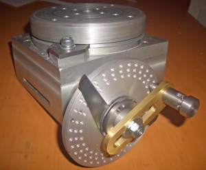
Then I cut a 12mm thick disc off some 40mm aluminium rod, faced it both sides and drilled a 16mm hole through it; this will become the Zero/Vernier plate. I then located it on the eccentric"s bearing bore with a bit of 16mm rod and marked hole positions for drilling it"s mounting holes by twirling the 2.5mm drill through the holes drilled in the eccentric. Then I drilled 3mm holes trough the plate on the marks, and counterbored the holes to 5.5mm to clear M3 cap screw heads. I also turned the end of a standard 8mm nut down to engage a bearing center like the collar I made earlier. Here is the collection of parts to make up the RT drive unit:
Then I marked and drilled a 3.2mm hole from the top of the RT base through into the eccentric hole, and then opened it up part way down to 4.2mm and tapped M5. A short bit of 3.2mm bronze brazing rod to locate in the groove and a cap screw (for now) to tighten it down:
New: A brand-new, unused, unopened, undamaged item in its original packaging (where packaging is applicable). Packaging should be the same as what is found in a retail store, unless the item was packaged by the manufacturer in non-retail packaging, such as an unprinted box or plastic bag. See the seller"s listing for full details.See all condition definitionsopens in a new window or tab

15 Days Returnable Products are returnable on Amazon.sg within the 15 day return window for any reason on Amazon.sg. When you return an item, you may see an option for a refund or replacement. Replacements are only available for items that are sold and fulfilled by Amazon SG – see About Replacements and Amazon.sg Refunds Policy.
15 Days Returnable Products are returnable on Amazon.sg within the 15 day return window for any reason on Amazon.sg. When you return an item, you may see an option for a refund or replacement. Replacements are only available for items that are sold and fulfilled by Amazon SG – see About Replacements and Amazon.sg Refunds Policy.
15 Days Returnable Products are returnable on Amazon.sg within the 15 day return window for any reason on Amazon.sg. When you return an item, you may see an option for a refund or replacement. Replacements are only available for items that are sold and fulfilled by Amazon SG – see About Replacements and Amazon.sg Refunds Policy.
15 Days Returnable Products are returnable on Amazon.sg within the 15 day return window for any reason on Amazon.sg. When you return an item, you may see an option for a refund or replacement. Replacements are only available for items that are sold and fulfilled by Amazon SG – see About Replacements and Amazon.sg Refunds Policy.
15 Days Returnable Products are returnable on Amazon.sg within the 15 day return window for any reason on Amazon.sg. When you return an item, you may see an option for a refund or replacement. Replacements are only available for items that are sold and fulfilled by Amazon SG – see About Replacements and Amazon.sg Refunds Policy.
15 Days Returnable Products are returnable on Amazon.sg within the 15 day return window for any reason on Amazon.sg. When you return an item, you may see an option for a refund or replacement. Replacements are only available for items that are sold and fulfilled by Amazon SG – see About Replacements and Amazon.sg Refunds Policy.
15 Days Returnable Products are returnable on Amazon.sg within the 15 day return window for any reason on Amazon.sg. When you return an item, you may see an option for a refund or replacement. Replacements are only available for items that are sold and fulfilled by Amazon SG – see About Replacements and Amazon.sg Refunds Policy.
15 Days Returnable Products are returnable on Amazon.sg within the 15 day return window for any reason on Amazon.sg. When you return an item, you may see an option for a refund or replacement. Replacements are only available for items that are sold and fulfilled by Amazon SG – see About Replacements and Amazon.sg Refunds Policy.
15 Days Returnable Products are returnable on Amazon.sg within the 15 day return window for any reason on Amazon.sg. When you return an item, you may see an option for a refund or replacement. Replacements are only available for items that are sold and fulfilled by Amazon SG – see About Replacements and Amazon.sg Refunds Policy.
15 Days Returnable Products are returnable on Amazon.sg within the 15 day return window for any reason on Amazon.sg. When you return an item, you may see an option for a refund or replacement. Replacements are only available for items that are sold and fulfilled by Amazon SG – see About Replacements and Amazon.sg Refunds Policy.
15 Days Returnable Products are returnable on Amazon.sg within the 15 day return window for any reason on Amazon.sg. When you return an item, you may see an option for a refund or replacement. Replacements are only available for items that are sold and fulfilled by Amazon SG – see About Replacements and Amazon.sg Refunds Policy.
15 Days Returnable Products are returnable on Amazon.sg within the 15 day return window for any reason on Amazon.sg. When you return an item, you may see an option for a refund or replacement. Replacements are only available for items that are sold and fulfilled by Amazon SG – see About Replacements and Amazon.sg Refunds Policy.
15 Days Returnable Products are returnable on Amazon.sg within the 15 day return window for any reason on Amazon.sg. When you return an item, you may see an option for a refund or replacement. Replacements are only available for items that are sold and fulfilled by Amazon SG – see About Replacements and Amazon.sg Refunds Policy.
15 Days Returnable Products are returnable on Amazon.sg within the 15 day return window for any reason on Amazon.sg. When you return an item, you may see an option for a refund or replacement. Replacements are only available for items that are sold and fulfilled by Amazon SG – see About Replacements and Amazon.sg Refunds Policy.
15 Days Returnable Products are returnable on Amazon.sg within the 15 day return window for any reason on Amazon.sg. When you return an item, you may see an option for a refund or replacement. Replacements are only available for items that are sold and fulfilled by Amazon SG – see About Replacements and Amazon.sg Refunds Policy.
15 Days Returnable Products are returnable on Amazon.sg within the 15 day return window for any reason on Amazon.sg. When you return an item, you may see an option for a refund or replacement. Replacements are only available for items that are sold and fulfilled by Amazon SG – see About Replacements and Amazon.sg Refunds Policy.
15 Days Returnable Products are returnable on Amazon.sg within the 15 day return window for any reason on Amazon.sg. When you return an item, you may see an option for a refund or replacement. Replacements are only available for items that are sold and fulfilled by Amazon SG – see About Replacements and Amazon.sg Refunds Policy.
15 Days Returnable Products are returnable on Amazon.sg within the 15 day return window for any reason on Amazon.sg. When you return an item, you may see an option for a refund or replacement. Replacements are only available for items that are sold and fulfilled by Amazon SG – see About Replacements and Amazon.sg Refunds Policy.
15 Days Returnable Products are returnable on Amazon.sg within the 15 day return window for any reason on Amazon.sg. When you return an item, you may see an option for a refund or replacement. Replacements are only available for items that are sold and fulfilled by Amazon SG – see About Replacements and Amazon.sg Refunds Policy.
15 Days Returnable Products are returnable on Amazon.sg within the 15 day return window for any reason on Amazon.sg. When you return an item, you may see an option for a refund or replacement. Replacements are only available for items that are sold and fulfilled by Amazon SG – see About Replacements and Amazon.sg Refunds Policy.
15 Days Returnable Products are returnable on Amazon.sg within the 15 day return window for any reason on Amazon.sg. When you return an item, you may see an option for a refund or replacement. Replacements are only available for items that are sold and fulfilled by Amazon SG – see About Replacements and Amazon.sg Refunds Policy.
15 Days Returnable Products are returnable on Amazon.sg within the 15 day return window for any reason on Amazon.sg. When you return an item, you may see an option for a refund or replacement. Replacements are only available for items that are sold and fulfilled by Amazon SG – see About Replacements and Amazon.sg Refunds Policy.
30 Days Returnable You may return most new and unopened Amazon International Store items within 30 days of delivery for a full refund of the price you paid. Unless otherwise stated, original delivery costs, Import Fees Deposit and return shipping for change of mind returns are not refunded. Change of mind returns within 30 days of receipt of delivery are easy with our online Returns Support Centre. Please note that it can take up to 15 days for an item to reach us once you return it. If we receive your returned item(s) after 45 days from receipt of delivery, we may deduct a 20% restocking fee from your refund.
You may return a defective, faulty, damaged, or incorrect item for a full refund of the price you paid, including original delivery costs, Import Fees Deposit and a credit of S$30 to cover reasonable substantiated delivery costs associated with returning the item(s) to us. If your reasonable return shipping costs exceed S$30, Contact us before shipping the item and provide evidence to us to substantiate the reasonable costs incurred, for which you will be reimbursed.

Centroid OEM Machine Tool Manufactures offer a wide variety of Centroid CNC equipped machine tools.. click to to find a Centroid equipped CNC machine tools..
Small Milling Machine CNC Control system: $18,385M400 3 axis with 1Kw AC Brushless Yaskawa servo motors and drivesMedium Milling Machine CNC control system: $22,175M400 3 axis with 2Kw AC Brushless Yaskawa servo motors and drivesLarge Milling Machine CNC Control system: $25,760M400 3 axis with 4.4Kw AC Brushless Yaskawa servo motors and drives
Knee Mills, Bed Mills, Routers:M400S $13,709 IN STOCK! Ready to Ship, use order #StockSFlat Bed Lathes, Small Slant Bed Lathes: T400S $13,279,click for pdf quote
Auto part set, Auto tool set, 3D contouring, 4th and 5th axis machining, Available in OEM configurations, Professional Installation with Service & Training and DIY CNC kits for both new machines and retrofit upgrades.
From the May issue of Modern Machine Shop Magazine " A CNC retrofit provides improved reliability and functionality compared to an older machine’s original control, and this is helpful in a number of ways. For example, a more intuitive control interface can help speed setups and minimize the chance for programming and/or setup mistakes, which could possibly damage or scrap a high-value work piece. Similarly, shops are also more confident in quoting work for large, expensive parts knowing the new control won’t hiccup partway through an operation and cause the part to be damaged. Shops also are better-positioned to take in “hot” jobs that require fast turnaround due to the retrofitted machine’s improved"... click here to see the complete article in PDF.
CENTROID Boss series II retrofit customer testimonial"The quality and workmanship of the CENTROID equipment was outstanding and very professional. CENTROID was able to custom tailor the control to allow us to continue to use our rotary milling arrangement as before and even expanded our capability. The short story is that we ended up with a four axis CNC mill for less than half the cost of the three axis Haas. This includes the work that was done by our staff."


 8613371530291