
edm rotary table free sample
Our product range includes single and multiple axes, tilt/rotating tables, and indexing and high-speed spindles. Additionally, we offer customized solution tables for customer requests or OEM projects.
Even for EDM machines that have been in use for decades, we will work with you to determine the ideal rotary indexing table and/or rotating/indexing spindle solution.
Our state-of-the-art rotary indexing tables and customizable reference and clamping systems provide endless application possibilities and highly efficient solutions.
Manufacturing on an EDM equipped with our high-speed rotating and indexing spindles is an efficient alternative to hard turning or superfinishing for rotationally symmetric parts. Even smallest parts (pins, needles etc.) in stainless steel, hard metal or even conductive ceramics, which cannot be made by conventional processes like turning, grinding etc. can be manufactured efficiently.
Anyway, to answer your questions, I looked up the Hirschmann table you referenced and it looks to me like it"s a spinner and indexer, not a turn while burn table.
Hirschmann must have a similar provision to integrate their turn while burn capable tables to whatever machines they are going to be run on...I don"t think you can just buy one and bolt it to a machine without the interface kit to mate it to the control.
Turn while burn requires that the controller governs the rotary motion; this is because the rate of rotation has to be driven by the spark gap conditions in conjunction with the axis motion of the rest of the machine whether it"s X or Y or U or V.
It was faked by tilting the wire to an angle other than the thread helix angle with the U axis, then driving a fine pitch helix with B and X (B is the rotary axis on my machine).
You can imagine just how many passes that would take (a LOT), and you will always have a 0.005" radius at the junction of each flank and the root, which may or may not be acceptable depending on the application.
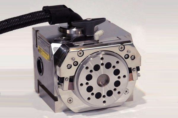
The rotary tables of our EDH-series have become an important key element for highly flexible automation applications. In contrast to our fixed-position EDX-series rotary tables, the flexible rotary tables are always equipped with an index cam with a constant pitch: resulting in an unchanged reduction ratio between the motor and the turntable plate. The partition is exclusively determined by the correspondence control unit of the servomotor.
Being flexible in use, the rotary tables of this type are particularly suitable for drive tasks in which the movement sequence has to be adapted in the production process, for example by new loads, new positions/end positions or travel directions. A typical example is the production of different vehicles on a production line, which makes flexible modification necessary in the production cycle.

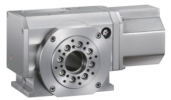
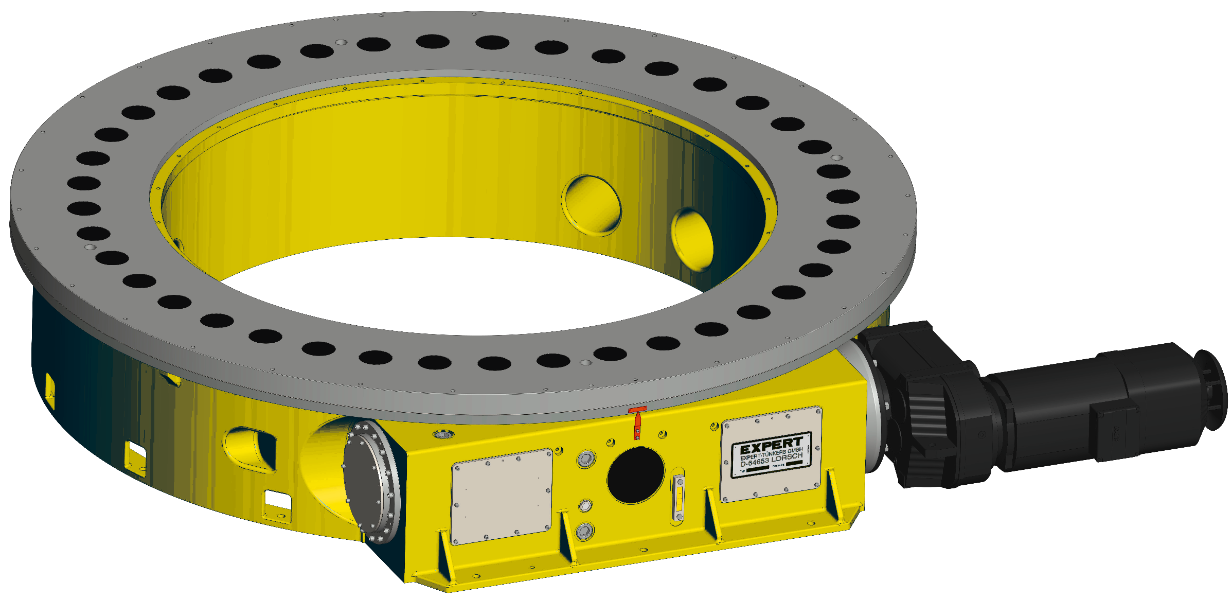
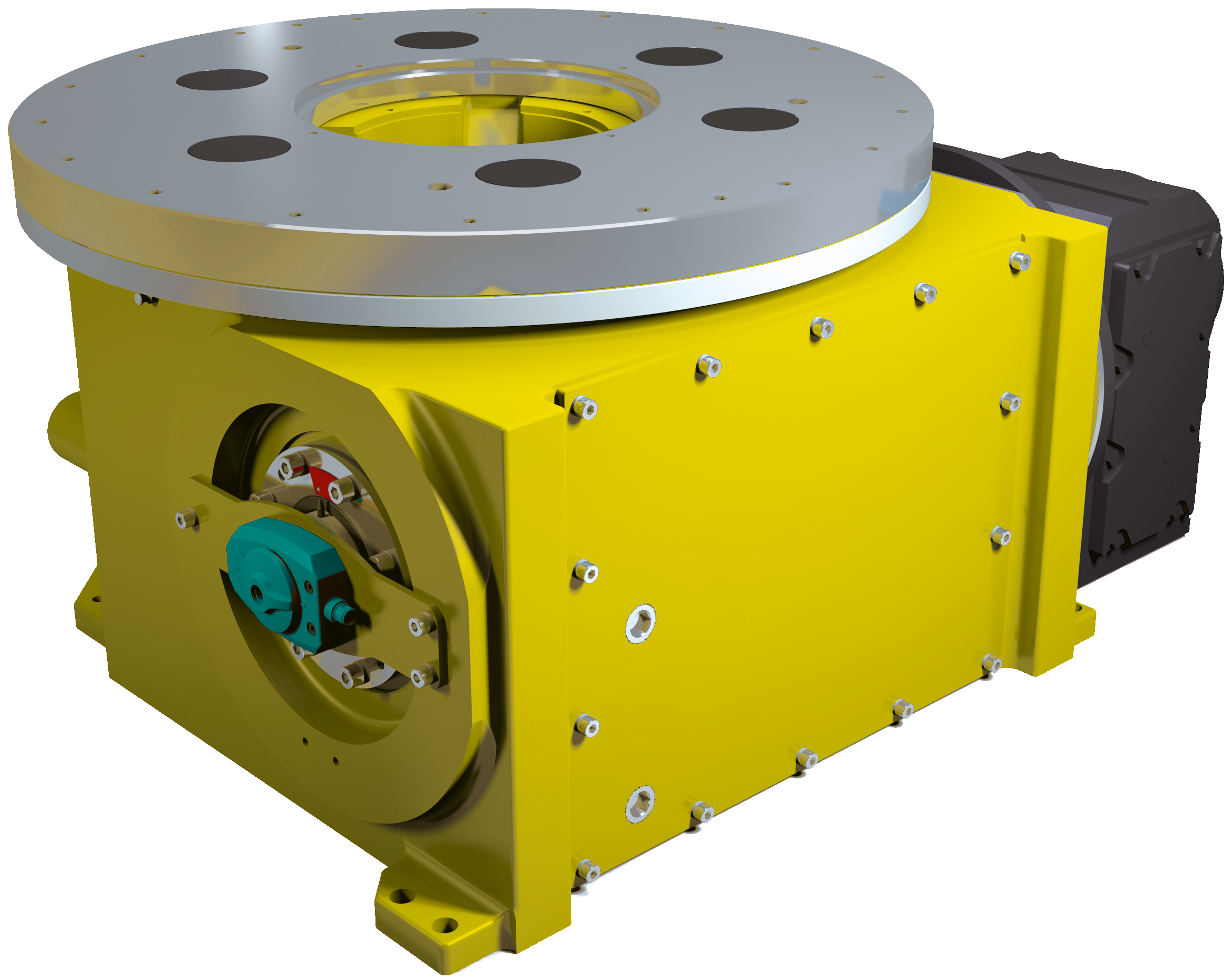
The rotary tables and trunnion drives of the EXPERT-TÜNKERS EDX series are precision indexer with fixed pitch and maximum torque. They are used for dynamic cycles of loads up to 20 tons. The drive takes place via an energy-efficient geared three-phase motor.
A characteristic of EDX Series rotary tables is the fact that the dial plate is continuously driven by two cam followers. In addition, this double meshing of the roller pins ensures virtually zero-backlash locking of the turntable plate in the operating position. Alternatively, this can be achieved by widening the zero position.
The indexing positions of the rotary table are defined in the motion profile specified in the indexing cam. Most common, partitions are 2-stop = 180°, 3-stop = 120° and 4-stop = 90°. Individual solutions are available on request.
Typical applications for EXPERT-TÜNKERS turntables are, for example, the change of work pieces in body shop welding systems, the insertion and removal of work piece carriers, or as a turntable for clocked work sequences in series production. The EDX Series of rotary tables are not only suitable for conventional use as rotary tables but also as trunnion drive units with a horizontal axis of rotation. These trunnion systems can provide several tooling’s for flexible production lines.
The EDX Series of rotary tables are not only suitable for conventional use as rotary tables but also as trunnion drive units with a horizontal axis of rotation. These trunnion systems can provide several toolings for flexible productionlines.
Sample Applications Sinking EDM • Undercuts • Tooth systems • Perforations Wire EDM • Curved shapes • Spirals Uniaxial rotary indexing tables Multi-axial rotary indexing tables Rotary indexing tables with hollow axle Rotating and indexing spindles Customized special solutions If requested, all rotary indexing tables can be equipped with a precise clamping system. Common characteristics • Complex shapes • Completely sealed (IP68) for use in dielectric fluid • Maintenance-free, patented EDM power transmission for wire EDM • Maintenance-free AC drive • Applicable on any EDM, laser oder HSC...
Rotary Indexing Table Goes Digital - for digital control during manufacturing process Functions: • Measuring and reporting of temperature and humidity inside the axis. • Readable using an app via Bluetooth on tablet or smartphone. • Data is transmitted, can be read out, evaluated and corresponding statistics on minimum-maximum-average-standard deviations can be generated • Values can also be read directly from LED display on the rotary table without any technical devices • Configuration of limit values for monitoring with visual and acoustic alarm function Advantages: • Increase of humidity...
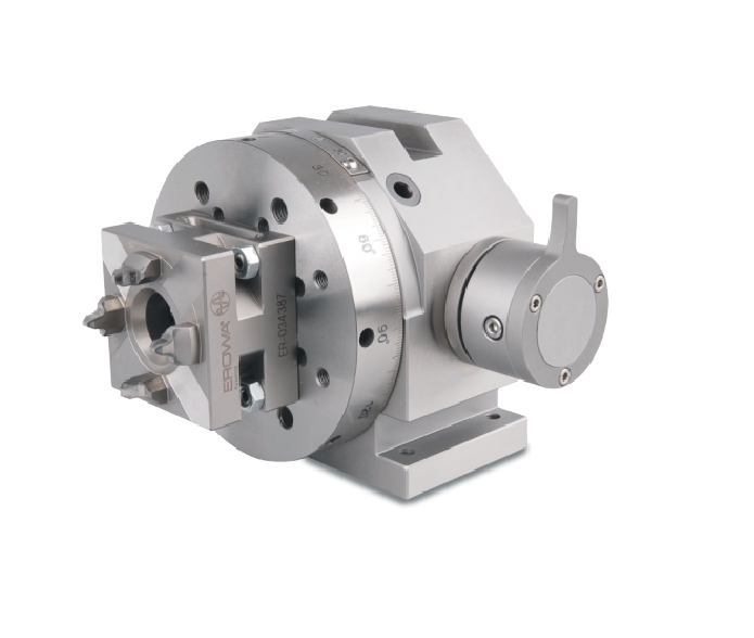
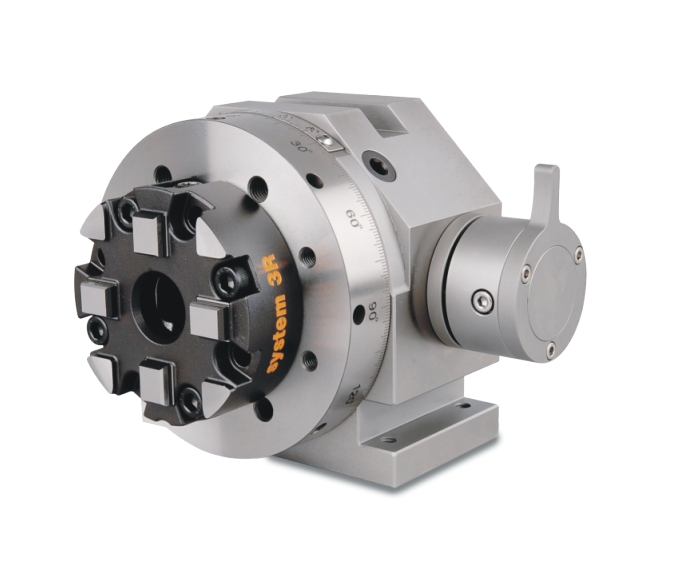
Uni-axial Rotary Indexing Tables At Carl Hirschmann all parts are homemade with high technical know-how and are assembled professionally to complete units consisting of rotary indexing table, palletizing and clamping system. With uniaxial rotary tables a vertical and horizontal machining with best positioning accuracy, concentricity and axial run-out accuracy is possible. If requested uniaxial rotary indexing tables can be delivered also with SK or HSK tapers. Two-axial Rotary Indexing Tables Our two-axial rotary indexing tables stand for highest precision, accuracy and continuity. The...
Hollow Axes With our precise uniaxial and two-axial rotary indexing tables with hollow axle the workpiece can be machined up to its center. Wire EDM is possible also for small workpieces. Customized solutions Due to our high manufacturing depth it is guaranteed to our customers that all components are made and not only assembled by Carl Hirschmann. We are pleased to meet individual customer requirements. Please contact us directly to find the perfect product for your demand. Carl Hirschmann - System provider with more than 4 0 years of experience For more than 40 years Carl Hirschmann...
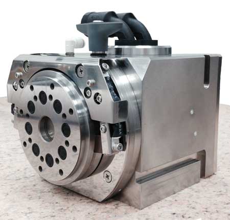
The robust geared rotary tables of the 500 series are extremely flexible to use and, thanks to the combiFLEX® modular system, can be converted or extended at any time to meet new machining tasks. The rotary tables are not only suitable for positioning operation, but can also be used for short simultaneous machining operations. The preloaded gear and the powerful bearings allow high long-term accuracies as well as large spindle loads. The maximum clamping force of up to 7,000 Nm leaves hardly anything to be desired.
The present invention relates to electrical discharge machining and, more particularly, to positioning workpieces on work tables of traveling wire-type electrical discharge machines ("EDM machines") so that contoured parts may be accurately cut and shaped and finally finished from the workpieces. Still more particularly, the present invention relates to methods and apparatuses for automatically controlling the relative movement between the work tables and traveling wire electrodes of EDM machines.
Electro-erosion machining of metal parts by electric discharge cutting or contouring is generally well-known. The process calls for juxtaposing a traveling, continuous wire-type electrode and a moving table or pair of tables on which a metal workpiece is mounted. A start hole is pre-drilled in the workpiece for threading the wire electrode. The wire travels from a supply reel so that new electrode wire surfaces are continually introduced to the erosion process. The table or tables move to continually position a metal workpiece, which is mounted on the table or tables, relative to the wire according to the progress of the process and the desired geometry for the finished part to be machined out of the workpiece, whereby electrical energy taking the form of successive electrical discharges between the moving wire and the workpiece is applied through a machining fluid constituted by a liquid dielectric. The electric energy removes material from the workpiece as the table or tables continually position the workpiece relative to the axially moving wire.
Conventionally, the workpiece is mounted or clamped to a work block on the work table or work tables of the standard wire EDM machine. Typically, programmable drives move the table or tables and workpiece along orthogonal axes, labeled "the X axis" and "the Y axis", to generate a machining path conforming to the desired contour shape. It is to be appreciated that the table or tables are capable of performing for both straight line motions and continuous path contouring. The workpieces are machined using power settings to achieve high metal removal rates. High speed machining, however, sacrifices both accuracy and surface finish.
Certain parts, for example, circular cams that are machined out of large plate or block workpieces, must be machined for highly accurate contours and exact surface finishes. Such precision machining is accomplished by re-machining the cut parts or "skim cutting" them several times to achieve a desired finished. But to skim cut, the workpiece must be held on the work table fixture or fixtures in its original position for the several passes. Where, as in some machines, the workpiece is clamped between two tables, the workpiece falls free when it is initially cut, virtually foreclosing the possibility of relocating and mounting the workpiece for secondary skim cutting.
To avoid this difficulty, it is a common practice to program the machining path so that parts of the workpiece will be left connected to the primary work block to form support bridges. Subsequent remachining or "skim cutting" can then be performed without the workpiece moving in relationship to the table axes. The connecting links may subsequently be cut with excess stock left on the workpiece to allow for finishing the bridge surface close to the "skim cut" part surface. This procedure, however, requires additional start holes to be pre-drilled within the workpiece to allow for rethreading the wire electrode on opposite sides of the support bridge.
Accordingly, it is the primary object of the present invention to provide a method and apparatus for controlling the relative movement of at least one electrode of an EDM machine and at least one workpiece with respect to one another so as to describe a continuous curvilinear path.
Another object of the present invention is to provide a method and apparatus for controlling the relative motion between an electrode of an EDM machine and a workpiece to describe a continuous curvilinear path that is capable of being repeatedly followed to achieve high metal removal rates without sacrificing accuracy of the contour and the surface finish of a machined finished part.
Yet another object of the present invention is to provide a method and apparatus for controlling the relative motion between an electrode of an EDM machine and a workpiece to describe a continuous curvilinear cutting path that produces the highly accurate contours and exact surface finishes required for certain machine parts, as in the case of a circular cam that is machined out of a large plate or block workpiece by a process of "skim cutting" the workpiece several times to achieve a desired finish.
A related object of the present invention is to provide a work table on which a workpiece may be accurately held in its original position with respect to a cutting electrode for the several passes required by the process of "skim cutting" the workpiece several times to achieve a desired finish.
Still another related object of the present invention is to provide a rotary work table that may be used in combination with an EDM machine to accurately hold a workpiece in its original position for the several passes required by the process of "skim cutting" a workpiece to produce a rounded finished part, as for example, a circular cam.
In accordance with the invention, there is described an improvement in the method of programmatically controlling the relative movement between at least one electrode of an EDM machine and at least one workpiece. The relative movement includes at least one curve defined by information from a software program. The improvement is in several steps. One step calls for fixedly positioning the workpiece with respect to a reference axis. Another step calls for orienting the reference axis with respect to a home position. Still another step calls for receiving information from the software program regarding an angle to which the reference axis is to be rotated with respect to the home position. Yet another step calls for rotating the reference axis and the workpiece about a rotation axis until the reference axis is aligned at the angle position. Another step calls for resetting the reference axis to the home position. A further step calls for repeating the previously described steps. Still further steps may include translating either the electrode or the workpiece along a translation axis, receiving information from the software regarding compensations in the path of relative movement between the electrode and the workpiece and compensations in power settings, and repeating all the steps while accommodating the path and power compensations to achieve the desired results of skim cutting.
Also in accordance with the invention, a rotary table assembly is adapted to carry out the steps of the improvement in the method as described. Rotation of the table achieves relative movement between at least one electrode and a workpiece to describe a path for producing a desired contour of a workpiece. The table provides a means for rotating the workpiece about an axis of rotation to an orientation in which the electrode is coincidental with the workpiece at a point on the path. Accordingly, the table is a part of a combination that in one embodiment of the invention also comprises a means for providing a certain distance between at least one electrode and an axis of rotation by translating the table to provide for a distance corresponding to the distance between a point on the path and the axis of rotation. This latter means may alternatively be a part of a mechanism for advancing the electrode, rather than the table, along an axis of translation.
Because the rotary table assembly is to be used in an environment in which a dielectric fluid is to be directed, by nozzles, to the workpiece supported on the table, which will result in the table and its fixtures being splashed and sprayed by the fluid, all externally exposed details of the table assembly are protected by electroless nickel plating, and sensitive parts are protected by splash guards of the same plating. Alternatively, these parts may be fabricated from stainless steel. In either case, internal parts are isolated from the dielectric fluid by wiper seals and an air pressurization system.
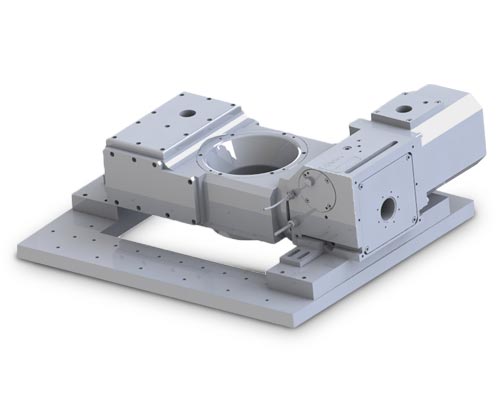
FIG. 1 is a partial front perspective view of a machine tool and rotary table for an EDM machine incorporating one embodiment of the present invention;
Referring first to FIG. 1, there is shown an EDM machine, indicated generally by the numeral 10. The EDM machine includes a base 11 which may have a dielectric fluid reservoir and a dielectric fluid temperature control unit built into it. Both are for handling a dielectric fluid used in the EDM operation, so that the dielectric fluid, reservoir, and temperature control unit together form a dielectric system. Those skilled in the art are aware that the dielectric system need not be an integral part of the machine base. In fact, many of those skilled in the art would prefer the known system of a separate dielectric tank located adjacent to the machine because of its convenience in maintenance and servicing.
The dielectric fluid may be either a deionized water supply or, alternatively, kerosene or a like light cutting oil. Throughout the cutting operation, a stream of dielectric fluid is continuously directed at an electrode wire 17 and a workpiece situated on a rotary table top 25, as for example the workpiece 26 which will be discussed later as situated on table top 25 of FIG. 2, to maintain flow around the gap between the electrode and the workpiece, from either or from both upper and lower directions. The invention includes means to protect against this potentially corrosive condition to parts of the EDM machine by means also to be later explained.
The table top 25 is included in a rotary table assembly 12, which is an improvement to the EDM machine 10. Typically, workpiece tables for EDM machines have programmable travel tables along axes orthogonal to each other, usually labeled the X and Y axes. Associated with movement along the X and Y axes are X and Y table drives, not shown. In accordance with the present invention, the rotary table assembly 12 has a programmable travel along the X axis, with the unused table drive, that conventionally would be the Y table drive, being used to power and control rotation of the table top 25 as will be discussed later. Plastic removable shields, fashioned as a four-sided work pan 13, surround a work area to contain the dielectric fluid.
A machine column is indicated generally by the numeral 14 and includes a height adjustment head 15 which is adjustable through an associated precision rack and gear arrangement to bring a wire guide system close to the workpiece to maintain accuracy.
Referring now to FIG. 2, it is seen that the rotary table assembly 12 includes a rotary table 24 that includes the rotary table top 25, on which a workpiece, here a rotary cam 26, is situated. The table top 25 is rotatable clockwise or counterclockwise with respect to a reference axis X--X, shown in this embodiment to pass through the axis of rotation R--R (see FIG. 3) of table top 25. In FIG. 2, the table is shown to have rotated through an angle θ, which is the angle between axis X--X and a reference line A--A. Accordingly, the angle θ represents the angle through which the table has rotated from an indexing position in which the reference line A--A is aligned with the X axis.
An initial position, in which reference line A--A is aligned with the X axis, is indexed by a home switch assembly 27. The home switch 27, which is a cam-operated limit switch, serves to indicated that the table top is close to the home position. A true home position is electronically preset into a D.C. motor control system 111 and 105 (FIG. 5) and 34 (FIGS. 2 and 4), by a home position set switch (not shown). The rotary table is under closed loop position control and will return to its precise home position from any rotational angle θ away from the preset home position, either by program control or by a manually-operated home switch.
Referring now to FIG. 3 in addition to FIG. 2, it is seen that the table 24 extends downwardly into a table base 28. Table 24 is supported for rotation in base 28 by retainer ball bearing assemblies 30. As can be seen, table bearing assemblies 30 are protected by shield 29. Shield 29 also provides a contact ring for a D.C. power brush assembly 43.
The D.C. power brush assembly 43 is an integral part of the EDM table operation. By its very juxtaposition to the rotary table 24, it provides a novel means of supplying polarity to the workpiece. Other means would pose problems because of the dynamics and structure of the rotary table assembly 12. For one example, if the positive polarity of the D.C. machining power were connected directly to the workpiece, the cable connection might become entangled as a result of the rotary motion. For another, if the positive polarity of the D.C. machining power were connected to the table base 28, the machining current passing through the base 28 might result in a failure of bearing parts within the base 28.
Table 12 may be optionally designed for additional support by an air bearing which operates by pressurized air introduced into the base 28 through a connector fitting 31. By this option, air introduced to the base 28 would pressurize the spaces between the table structure 25 and the base 28 to support the table 24 with table top 25 within the base 28. In the preferred embodiment, however, the connector fitting 31 provides pressurized lubricated air to the table base to prevent fluid from entering the base housing. Air is supplied by conventional means, not shown, including an air filter, an air regulator and an air lubricator, with the latter means providing atomized lubrication to the rotary table assembly. A press ball bearing assembly 32 contains the table top 25 within the base 28. An axial preload on the table assembly 12 is set by spacers (not shown) between a pack hub 33 and the table top 25 and the inner race of ball bearing assembly 32.
Still referring to FIGS. 2 and 3, the rotary table 25 is driven by a DC servo motor and encoder 34. As is well-known, the DC motor can be very accurately controlled by the application of a variable voltage. The motor drives a pulley 35 which, in turn, drives a belt 36 causing a table pulley 37 to rotate concomitantly. Table pulley 37 is received around a worm shaft 38. Accordingly, rotation of the table pulley 37 rotates worm shaft 38. As can be seen in FIG. 3, worm shaft 38 engages the threads of a worm gear 39 connected to table 25. Rotation of the worm shaft 38, then, causes worm gear 39 and table 25 to rotate. These linkages of rotating pulleys and shafts connects table 24 to motor 34 so that rotation of table 24 and table top 25 is in direct response to the motor.
As should have been anticipated by the earlier discussion regarding splashing of the dielectric fluid, the invention has a means of protecting moving parts of the rotary table assembly 12. According to this aspect of the invention, splash plates or guards 40 are provided to keep the dielectric fluid from splashing upon critical parts of the rotary table assembly 12, including the D.C. motor and encoder 34. Also, all parts of the assembly that might be subjected to splashing by the dielectric fluid are preferably protected by nickel plating or are fabricated from stainless steel.
Control of the rotary table 25, as it cooperates in producing relative movement between the electrode 17 and the workpiece 26, including relative translation along the X--X axis, will now be explained with reference to FIG. 5. Information is fed by conventional means into a control system that includes input devices 100, a memory 108, a central processing unit (CPU) 109, and output devices 110, all of which lead to resulting operations of operating devices 113, 114.
The information carrier 101 is fed into an information controller 102, preferably a magnetic media controller as, for example, a disk or cassette reader. Other information, such as variables which adapt the software program to a particular application, may be fed into the system via a keyboard or pushbuttons at an operator"s station 103. Still other information may be fed into the system by discrete machine based input devices 104, such as limit switches or the like. Particular information, highly pertinent to the EDM operation, regarding the positioning feed rate of the workpiece with respect to the wire electrode is also fed into the system via a feed rate control 105. Finally, encoding devices 106, 107, one of which is included in the servo motor and encoder 34, input information into the system as a feedback of the output by motors electrically linked to the encoder devices.
Input signals are bussed to the CPU 109 and memory 108 for the information to be processed by the CPU 109 or stored in the memory 108. Information stored in the memory 108 will be later sent to the CPU 109 to be processed, and information processed by the CPU may be sent to memory 108 for later return for further processing by the CPU 109. The CPU 109 processes the information into characteristic points on the path of the X--X axis with respect to the angular rotation of table 25. This includes whether the path is traversed for the first time or whether it is a secondary pass for skim cutting, with regard to whether the table is reset to the home position. In this process, the width of the operating gap between the electrode 117 and the workpiece 126 is to be considered. It should be appreciated that operations which result in rotation of table top 25 and linear translation of the electrode wire 17 relative to table top 25 progress according to stored program data and a closed loop positioning control, as would be the case of X and Y operations which would result in standard X--Y wirecut EDM known to those of ordinary skill in the EDM technology. Accordingly, the feed rate of the positioning servo system is regulated by a feed rate control 105, which monitors the machining gap voltage developed between the wire electrode 117 and the workpiece 126, both schematically represented to the right of FIG. 5.
The characteristic points of the workpiece contour supplied to the information carrier differ from the curve path of relative movement between the workpiece 126 and the wire electrode 117. Compensation must accordingly be made in the wire path and power settings when the program is recalled for skim cutting. Also, it should be noted that the programmed position of the axis along which the electrode is guided will have to be altered according to a desired cam profile. When the profile angle is other than 0 degrees, the true position of the wire path from the table rotating axis must increase in relationship to the profile angle to compensate for the change in the true contact point between the wire electrode and the cam profile. Output signals are bussed to output devices 111, 112, from which the signals pass to result in the relative movement of electrode 117 and workpiece 126, of which the driving motors 113, 114 rotate and displace, respectively, the moving parts of table system 12. The wire electrode 117 describes the curve path and cuts the curve portion from the workpiece 126 as per the data supplied by the software.
The encoder 106, which is included in the motor and encoder 34, monitors the rotation of table top 25 to feed back this information into the CPU 109 for further processing. In this manner, the encoder 106 attached to the motor 113, which is the motor of the combined motor and encoder 34 referred to earlier as rotating table 24, and the encoder 107 attached to the motor 112 for relative translation between the electrode 117 and the workpiece 126 along the X--X axis convert the output signals to represent the characteristic points of the curve path of the workpiece contour.
The invention as described and shown in the figures of the drawings provides a convenient means of programming the relative movement of the wire electrode 17 and the workpiece 26 on polar coordinates. Various changes and modifications may be made within the inventive concept without departing from the spirit of the invention. For example, in the preferred embodiment, the table is shown in FIG. 2 as being translated along the X--X axis for relative movement between the electrode 17 and the work table assembly 25. It is known in the art that the electrode itself may be translated relative to the work table. Thus, it is contemplated that an embodiment of the invention as shown in FIG. 6 might provide for translation of the electrode 17 along the X--X axis, as for example by translating the machine column 14 to provide for the same relative motions between the electrode 17 and the work table assembly 25 as when the rotary table is translated. It should be appreciated that a work table 41, with a clamp 42 for holding the workpiece 26 thereon, might be provided within the work pan 13 when the work pan is rotated on the work table 25 in the embodiment of FIG. 6.

The high-speed generating LN2WH Control uses a Windows platform. The system was designed to provide a user-friendly environment for the operator and still have the high-level functionality that is required in today’s demanding world. The control is network capable, which will allow for NC sharing, remote monitoring and messaging via LAN (option). The LN2WH Control automatically generates cutting conditions, offsets, corner control settings, wire speed, wire tension and other data necessary for proper operation. This is especially helpful to novice EDM operators, since no prior knowledge of EDM is necessary to achieve excellent results.
EDM Network Inc. is the exclusive US importer of CHMER and AMStech EDMs. Below are a variety of Product and Support videos related to the products we offer. The most popular videos will be found under the Featured Videos category. If you have any questions or comments feel free to contact us toll free at 888-289-3367 or email us at [email protected].


 8613371530291