
false rotary table c plate supplier

Drilling involves pipe handling operations in a wellbore, and this in turn requires a false rotary table, a vital cog in the overall success of the operations. At ShalePumps, the need for constant improvement has resulted in an extensive range of precision engineered equipment, of which the false rotary table occupies the limelight.
This hydraulically driven false rotary table is guaranteed to seamlessly engage the tubulars in the wellbore. Pivotal to drilling operations are the sequence of engaging and lowering tubulars into the wellbore. The false rotary table manufactured at our facility is a fine example of harmony between design, materials and precision engineering.
Featuring a mighty load capacity of 1.3 million pounds operating at a maximum speed of 20 rpm, the false rotary table assists the drilling operations in continuous long drawn operations. Pipe handling requires the seamless and sturdy operation of the false rotary table.
ShalePumps, backed by substantive body of experience and knowhow has developed this high performance false rotary table to ably support drilling operations by incorporating a blend of advanced materials and precision engineering. With a guaranteed long life and trouble free run, the ShalePumps false rotary table spins other models out of reckoning.

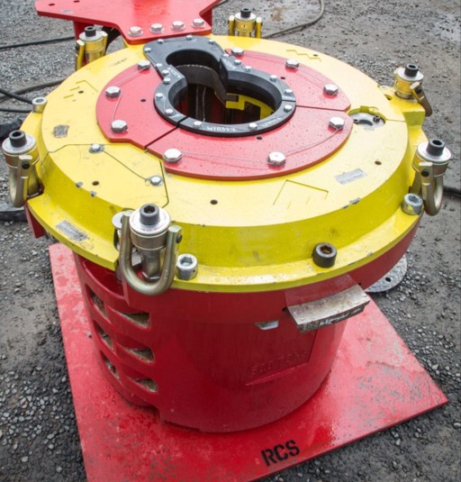
A drilling rig is not complete without the rotary table, a mechanical device that provides a clockwise rotational force to a drill string and enable the drilling of a borehole. The rotary speed is identified as rpm (rounds per minute) the amount of times the device can complete a full revolution per minute. When the drilling process covers the pipe handling operation in the wellbore, it will require a false rotary table for higher chances of success. Shale Pumps provides this device as a hydraulically driven equipment to seamlessly engage tubulars in a wellbore. We manufacture false rotary tables in-house to ensure precision engineering and the highest-quality design and materials.
When it comes to pipe handling, it is crucial for equipment to be seamless and sturdy to be reliable. Shale Pumps’ false rotary table can handle up to 1.3 million pounds of load while maintaining constant operation at a 20 rpm on maximum speed, making it ideal for long drawn and continuous operations. We developed our false rotary tables, like the SP-FRT375 to perform in the most demanding drilling jobs, and we achieve this only with precision engineering and by using advanced materials.
The false rotary table at Shale Pumps is backed by a guarantee for longevity and trouble-free performance. This way, it outperforms false rotary tables offered by other manufacturers. Our device helps you save money and boost productivity in the long run with lower maintenance costs. Every rotary table equipment has been tested in compliance with the latest industry regulations for safety, efficiency, and quality.
When choosing a false rotary table, be sure that it is being sold by a reputable manufacturer and supplier, like Shale Pumps. That way, you can be sure that the equipment has been manufactured and assembled following a strict and proven format, which ensures its quality. Shale Pumps corrects any material defects and problems with assembly immediately and take note of them to prevent them from occurring again.
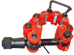
Diversified offers a wide range of Manual Elevators such as Side Door Elevators, Single Joint Elevators, Slip Type Elevators, Safety Clamps and Rotary Slips for 2-3/8” diameter tubing to 30” diameter casing.
Side Door Elevators:Used for handling collar type casing, all of our Side Door Elevators are equipment with a safety latch lock. Our Side Door Elevators come in SLX 150-250 Ton variants from 4-1/2” to 30” OD.
Single Joint Elevators:The SJX Single Joint Elevator is designed for running single joints of tubing and casing from V-door to well center. Our inventory of SJX Single Joint Elevators range from 2-3/8” up to 30”. All comes with load tested Slings and Swivels.
Slip Type Elevators:Our Slip Type Elevators comes in HYC 200 Ton, YT 150 Ton and YC 75 Ton variants. With Slip and Inserts to accommodate 7” Casing down to 2-3/8” Tubing. We can also provide Low Penetrating Dies for Chrome running and handling applications upon request.
Safety Clamps:Used to secure flush tubular products during installation. Our inventory of MP series and Type “C” and “T” Safety Clamps are available from 2-3/8” to 30” OD. We can also provide Low Penetrating Dies for Chrome running and handling applications upon request.
Rotary Slips:Our inventory of Rotary Slips includes SDS, SDML, SDXL and CMS-XL variants from 2-3/8” to 30” OD. We can also provide Low Penetrating Dies for Chrome running and handling applications upon request.
Diversified also offers the following equipment to complete your Casing and Tubing Running Needs: Thread Protectors, Stabbing Guides, Drifts, Bowl & Slips, C-Plate)
Thread Protectors: We offer Air Operated or Clamp-on Type Thread Protectors to offer safe, reliable casing and tubing pin-end protection from 20” casing down to 2-3/8” tubing.
Stabbing Guides:Stabbing Guides are engineered to consistently align and safely guide two sections of pipe together through the use of specially formed polyurethane shells, thereby greatly reducing the chance of pin or box damage. We offer stabbing guides from 13-3/8” casing down to 2-3/8 tubing”.
This website is using a security service to protect itself from online attacks. The action you just performed triggered the security solution. There are several actions that could trigger this block including submitting a certain word or phrase, a SQL command or malformed data.

oooii This application claims benefit of United States provisional patent application serial number 601504,427, filed September 19, 2003, which is herein incorporated by reference.
(0002] Embodiments of the present invention generally relate to handling tubulars. More specifically, embodiments of the present invention relate to connecting and lowering tubulars into a weflbore.
[00031 In conventional well completion operations, a welibore is formed to access hydrocarbon-bearing formations by the use of drilling. In drilling operations, a drilling rig is supported by the subterranean formation. A rig floor of the drilling rig is the surface from which tubular strings, cutting structures, and other supplies are lowered to ultimately form a subterranean weilbore lined with casing. A hole is formed in a portion of the rig floor above the desired location of the welibore. The axis that runs through the center of the hole formed in the rig floor is well center.
[0004] Drilling is accomplished by utilizing a drill bit that is mounted on the end of a drill support member, commonly known as a drill string. To drill within the weilbore to a predetermined depth, the drill string is often rotated by a top drive or rotary table on the drilling rig. After drilling to a predetermined depth, the drill string and drill bit are removed and a section or string of casing is lowered into the weilbore.
[0005] Often, it is necessary to conduct a pipe handling operation to connect sections of casing to form a casing string which extends to the drilled depth. Pipe handling operations require the connection of casing sections to one another to line the welibore with casing. The casing string used to line the weilbore includes casing sections (also termed "casing joints") attached end-to-end, typically by threaded connection of male to female threads disposed at each end of a casing section. To install the casing sections, successive casing sections are lowered longitudinally through the rig floor and into the drilled-out wellbore. The length of the casing string grows as successive casing sections are added.
(0006] When the last casing section is added, the entire casing string must be lowered further into its final position in the weilbore. To accomplish this task, drill pipe sections (or "joints") are added end-to-end to the top casing section of the casing string by threaded connection of the drill pipe sections. The portion of the tubular string which includes sections of drill pipe is the landing string, which is located above the portion of the tubular string which is the casing string. Adding each successive drill pipe section to the landing string lowers the casing string further into the weilbore. Upon landing the casing string at its proper location within the weilbore, the landing string is removed from the wellbore by unthreading the connection between the casing string and the landing string, while the casing string remains within the welibore.
[0007] Throughout this description, tubular sections include casing sections and/or drill pipe sections, while the tubular string includes the casing string and the drill pipe string. To threadedly connect the tubular sections, each tubular section is retrieved from its original location on a rack beside the drilling platform and suspended above the rig floor so that each tubular section is in line with the tubular section or tubular string previously disposed within the wellbore. The threaded connection is made up by a device which imparts torque to one tubular section relative to the other, such as a power tong or a top drive. The tubular string formed of the two tubular sections is then lowered into the previously drilled welibore.
[0008] The handling of tubular sections has traditionally been performed with the aid of a spider along with an elevator. Spiders and elevators are used to grip the tubular sections at various stages of the pipe handling operation. In the making up or breaking out of tubular string connections between tubular sections during the pipe handling operation, the spider is typically used for securing the tubular string in the well bore. Additionally, an elevator suspended from a rig hook is used in tandem with the spider. In operation, the spider remains stationary while securing the tubular string in the weilbore. The elevator positions a tubular section above the tubular string for connection. After completing the connection, the elevator pulls up on the tubular string to release the tubular string from the slips of the spider. Freed from the spider, the elevator may now lower the tubular string into the welibore.
Before the tubular string is released from the elevator, the spider is allowed to engage the tubular string again to support the casing string. After the load of the tubular string is switched back to the spider, the elevator may release the tubular string and continue the makeup process with an additional tubular section.
[0009] The elevator is used to impart torque to the tubular section being threaded onto the tubular section suspended within the weitbore by the spider. To this end, a traveling block suspended by wires from a draw works is connected to the drilling rig. A top drive with the elevator connected thereto by elevator links or bails is suspended from the traveling block. The top drive functions as the means for lowering the tubular string into the wellbore, as the top drive is disposed on rails so that it is moveable longitudinally upward and downward from the drilling rig along the rotational axis of well center. The top drive includes a motor portion used to rotate the tubular sections relative to one another which remains rotationally stationary on the top drive rails, while a swivel connection between the motor portion and the lower body portion of the top drive allows the tubular section gripped by the elevator to rotate. The rails help the top drive impart torque to the rotating tubular section by keeping the top drive lower body portion rotationally fixed relative to the swivel connection. Located within the rig floor is a rotary table into or onto which the spider is typically placed.
[0010] Recently, it has been proposed to use elevators to perform the functions of both the spider and the elevator in the pipe handling operation. The appeal of utilizing elevators for both functions lies in the reduction of instances of grippingly engaging and releasing each tubular section with the elevator and the spider which must occur during the pipe handling operation. Rather than releasing and gripping repeatedly, the first elevator which is used to grip the first casing section initially may simply be lowered to rest on the hole in the rig floor. The second elevator may then be used to grip the second casing section, and may be lowered to rest on the hole in the rig floor.
(00111 To accomplish this pipe handling operation only with elevators, the first elevator must somehow be removed from its location at the hole in the rig floor to allow the second elevator to be lowered to the hole. This removal is typically accomplished by manual labor, specifically rig personnel physically changing the location of the first elevator on the rig floor. Furthermore, the purely elevator pipe handling operation requires attachment of the elevator links to each elevator when it is acting as an elevator, as well as detachment of the elevator links from each elevator when it is acting as a spider. This attachment and detachment is also currently accornphshed using manual labor. Manipulation of the elevator links and the elevator by manual labor is dangerous for rig personnel and time consuming, thus increasing well cost.
[0012] Manual labor is also used to remove the elevator or elevator slips (described below) when it is desired to lower the tubular, as well as replace the elevator or elevator slips when it is desired to grippingly engage the tubular.
[0013] Sometimes a false rotary table is mounted above a rig floor to facilitate wellbore operations. The false rotary table is an elevated rig floor having a hole therethrough in line with well center. The false rotary table allows the rig personnel to access tubular strings disposed between the false rotary table and the rig floor during various operations. Without the false rotary table, access to the portion of the tubular string below the gripping point could only be gained by ng hands venturing below the rig floor, which is dangerous and time-consuming. Manual labor is currently used to install and remove the false rotary table during various stages of the operation.
(0014] Typically, a spider includes a plurality of slips circumferentially surrounding the exterior of the tubular string. The slips are housed in what is commonly referred to as a "bowl". The bowl is regarded to include the surfaces on the inner bore of the spider. The inner sides of the slips usually carry teeth formed on hard metal dies for grippingly engaging the inside surface of the tubular string.
The exterior surface of the slips and the interior surface of the bowl have opposing engaging surfaces which are inclined and downwardly converging. The inclined surfaces allow the slip to move vertically and radially relative to the bowl. In effect, the inclined surfaces serve as a camming surface for engaging the slip with the tubular string. Thus, when the weight of the tubular string is transferred to the slips, the slips will move downwardly with respect to the bowl. As the slips move downward along the inclined surfaces, the inclined surfaces urge the slips to move radially inward to engage the tubular string. In this respect, this feature of the spider is referred to as "self tightening." Further, the slips are designed to prohibit release of the tubular string until the tubular string load is supported by another means such as the elevator. The elevator may include a self-tightening feature similar to the one in the spider.
[0015] When in use, the inside surfaces of the currently utilized slips are pressed against and "grip" or "grippingly engage" the outer surface of the tubular section which is surrounded by the slips. The tapered outer surface of the slips, in combination with the corresponding tapered inner face of the bowl in which the slips sit, cause the slips to tighten around the gripped tubular section such that the greater the load being carried by that gripped tubular section, the greater the gripping force of the slips being applied around that tubular section. Accordingly, the weight of the casing string, and the weight of the landing string being used to "run" or "land" the casing string into the weilbore, affects the gripping force being applied by the slips, as the greater the weight of the tubular string, the greater the gripping force and crushing effect on the drill pipe string or casing string.
(00161 A significant amount of oil and gas exploration has shifted to more challenging and difficult-to-reach locations such as deep-water drilling sites located in thousands of feet of water. In some of the deepest undersea wells, wells may be drilled from a drilling rig situated on the ocean surface several thousands of feet above the sea floor, and such wells may be drilled several thousands of feet below the sea floor, It is envisioned that as time goes on, oil and gas exploration will involve the drilling of even deeper holes in even deeper water.
(0017] For many reasons, the casing strings required for such deep wells must often be unusually long and have unusually thick walls, which means that such casing strings are unusually heavy and can be expected in the future to be even heavier. Additionally, the landing string needed to land the casing strings in such extremely deep wells must often be unusually long and strong, hence unusually heavy in comparison to landing strings required In more typical wells. Hence, prior art slips in typical wells have typically supported combined landing string and casing string weights of hundreds of thousands to over a million pounds, and the slips are expected to require the capacity to support much heavier combined weights of casing strings and landing strings with increasing time.
[0018] Prior art slips used in elevators and spiders often fail to effectively and consistently support the combined landing string and casing string weight associated with extremely deep wells because of numerous problems which occur at such extremely heavy weights. First, slips currently used to support heavy combined landing string and casing string weights apply such tremendous gripping force due to the high tensile load that the slips must support that the gripped tubular section may be crushed or otherwise deformed and thereby rendered defective. Second, the gripped tubular section may be excessively scarred and thereby damaged due to the teeth-like grippers on the inside surface of the slips being pressed too deeply into the gripped tubular section. Furthermore, the prior art slips may experience damage due to the heavy load of the tubular string, thereby rendering them inoperable or otherwise damaged.
[0019] A related problem involves the often uneven distribution of force applied by the prior art slips to the gripped tubular section. It the tapered outer wall of the slips is not maintained substantially parallel to and aligned with the tapered inner wall of the bowl, the gripping force of the slips may be concentrated in a relatively small portion of the inside wall of the slips rather than being evenly distributed throughout the entire inside wall of the slips, possibly crushing or otherwise deforming the gripped tubular section or resulting in excessive and harmful strain or elongation of the tubular string below the point at which the tubular string is gripped.
Additionally, the skewed concentration of gripping force may cause damage to the slips, rendering them inoperable or otherwise damaged. Rough welibore operations may cause the slips and/or bowl to be jarred, resulting in misalignment and/or irregularities in the tapered interface between the slips and the bowl to cause the uneven gripping force. The uneven distribution of gripping force problem is exacerbated as the weight supported by the slips is increased.
[0020] It is therefore desirable to provide a method and apparatus for supporting the weight of the tubular string during pipe handling operations with minimal crushing, deforming, scarring, or stretching-induced elongation of the tubular string.
It is further advantageous to provide a fully automated tubular handling and tubular running apparatus and method. There is a further need for apparatus and methods for utilizing a pipe handling system using elevators for the functions of both the elevator and the spider which are safer and more efficient than current apparatus or methods in use.
[0021] In one aspect, embodiments of the present invention provide an apparatus for handling tubulars, comprising at least two elevators for engaging one or more tubular sections, the at least two elevators interchangeable to support one or more tubular sections above a weilbore and to lower the one or more tubular sections into the welibore; and elevator links attachable to each elevator, wherein the elevator links are remotely transferable between the at least two elevators. In another aspect, embodiments of the present invention include a method of remotely transferring elevator links between at least two elevators, comprising providing elevator links attachable interchangeably to a first elevator and a second elevator; detaching the elevator links from the first elevator by remotely extending a distance between the elevator links; and attaching the elevator links to the second elevator by remotely retracting the distance between the elevator links.
[0022] In yet another aspect, embodiments of the present invention include a method of forming and towering a tubular string into a wellbore using a remotely operated elevator system, comprising providing elevator links attached to a first elevator and a sliding false rotary table located above a rig floor, wherein the false rotary table is disposed in a landing position to axially support a tubular; axially engaging the tubular with the first elevator; locating the First elevator substantially coaxial with the weilbore on the false rotary table; remotely detaching the elevator links from the first elevator; and remotely attaching the elevator links to a second elevator. Embodiments of the present invention also provide a false rotary table disposed above a rig floor for use in handling tubulars, comprising a table slidable over a weilbore; and a hole disposed in the table, wherein the table is slidable by remote activation from a first, pipe-supporting position to a second, pipe-passing position and, in the pipe-supporting position, the hole is located over the wellbore.
[0023] Embodiments of the present invention also provide a false rotary table disposed above a rig floor for use in handling tubulars, comprising a base plate having a hole therein disposed above a weilbore; and at least two sliding plates slidably connected to the base plate, wherein the at least two sliding plates are remotely and independently slidable over the base plate to alternately expose the hole or narrow a diameter of the hole. In an additional aspect, embodiments of the present invention provide an apparatus for grabbing an oil-field mechanism, comprising links operatively connected to an oil rig and capable of grabbing the mechanism; and at least one spreading member operatively connected to each link and disposed between the links, the spreading member comprising a motive member, wherein the spreading member is remotely operable.
[00241 In one aspect, the present invention provides at least two elevators which support the tubular string with minimal crushing, deforming, scarring, or stretching-induced elongation of the tubular string being engaged by one or more of the at least two elevators. In another aspect, the present invention advantageously provides an apparatus and method for fully automating a tubular handling and tubular running operation involving at least two elevators.
(00251 So that the manner in which the above recited features of the present invention can be understood in detail, a more particular description of the invention, briefly summarized above, may be had by reference to embodiments, some of which are illustrated in the appended drawings. It is to be noted, however, that the appended drawings illustrate only typical embodiments of this invention and are therefore not to be considered limiting of its scope, for the invention may admit to other equally effective embodiments.
[00271 Figure 2 is a perspective view of the automated false rotary table of Figure 1 in position to land a tubular on the rotary table for the threading of additional tubulars thereon.
[0028] Figure 3 shows the automated false rotary table of Figure 2 with a first tubular section landed on the false rotary table with a first elevator.
[0033] Figure 8 shows the second tubular section lowered through the automated false rotary table and the automated false rotary table moved back to the position for landing tubulars shown in Figure 2.
[0035] Figure 10 shows the automated false rotary table of Figure 9 with the second elevator and the second tubular section landed on the automated false rotary table. Elevator links are shown detached from the second elevator.
(00441 Figure 21 shows the automated false rotary table of Figure 20 in position to land a tubular on the automated false rotary table for the threading of additional tubulars thereon.
(00451 Figure 21 A is a section view of a portion of a first elevator and a portion of the automated false rotary table of Figure 21 on which the first elevator is disposed.
[0046] Figure 22 shows the automated false rotary table of Figure 20 in the position to land a tubular, as shown in Figure 21. A second elevator having a first tubular section therein is landed on the automated false rotary table.
(00481 Figure 24 shows the automated false rotary table of Figure 20 with elevator links in position to lift the first elevator from the automated false rotary table.
[0049] Figure 25 shows the automated false rotary table of Figure 20, with the first elevator lifting a first tubular string formed by a second tubular section connected to the first tubular section. The second elevator is in the open position.
(0050] Figure 26 shows the automated false rotary table moved to the tubular-running position shown in Figure 20. The second elevator is moved to a position away from a hole in the automated false rotary table into which tubutars are run.
(0051J Figure 27 shows the automated false rotary table of Figure 20 in the tubular-running position of Figure 26. The tubular string is lowered through the hole.
[0052] Figure 28 shows the automated false rotary table of Figure 20 moved to the tubular-landing position shown in Figure 21. The first elevator having a tubular therein is in position to land on the automated false rotary table.
(0054] Figure 29 shows the automated false rotary table of Figure 20 in the tubular-landing position, with the first elevator landed on the automated false rotary
[0056] Figure 30 shows the first elevator on the automated false rotary table of Figure 20 having the elevator link retainer assemblies in the open position. The elevator links are in position to move the elevator link retainer assemblies on the first elevator to the closed position to retain the elevator links therein.
[0057] Figure 31 shows the first and elevators on the automated false rotary table of Figure 20, with the elevator links in the process of moving the elevator link retainer assemblies of the second elevator into the closed, retaining position.
(0058] Figure 32 shows the second elevator on the automated false rotary table of Figure 20 being lifted from the automated false rotary table to lock the elevator link retainer assemblies into the locked, closed, link-retaining position.
(0064] When referred to herein, the terms "links" and "elevator links" also refer to bails, cables, or other mechanical devices which serve to connect a top drive to an elevator. The term "elevator," as used herein, may include any apparatus suitable for axially and longitudinally as well as rotationally engaging and supporting tubular sections in the manner described herein. The term "tubular section" may include any tubular body including but not limited to a pipe section, drill pipe section, and/or casing section. As used herein, a tubular string comprises multiple tubular sections connected, preferably threadedly connected, to one another. Directions stated below when describing the present invention such as left, right, up, and down are not limiting, but merely indicate movement of objects relative to one another.
(0065] Figure 1 shows a first embodiment of an automated false rotary table 10 in the position for running one or more tubulars (see Figures 3-12) into a weilbore (not shown) below the false rotary table 10. A drilling rig (not shown) is located above the wellbore. The drilling rig has a rig floor (not shown), above which the false rotary
[0066] The automated false rotary table 10 includes a sliding table 15 which is moveably disposed on a track 20. The sliding table 15 is slidable horizontally parallel to the track 20. Most preferably, although not limiting the scope of the present invention, the sliding table 15 is capable of supporting approximately 750 tons of weight thereon.
[0067] The sliding table 15 has a hole 19 therein. The hole 19 in the sliding table is shown with three portions, including a narrowed portion 16 having a smaller diameter, a widened portion 17 having a larger diameter relative to the narrowed portion 16, and a control line portion 18. The narrowed portion 16 is utilized to support the weight of one or more tubular sections when an elevator axially and rotationally engaging the one or more tubular sections is landed on the false rotary table 10 (described below). The widened portion 17, which in one preferable embodiment has a width of at least 36 inches, allows the one or moretubular sections to pass through the rotary table 10 after the elevator releases the one or more tubular sections (described below). In Figure 1, the false rotary is in the position to allow the one or more tubulars to pass through the widened portion 17.
The tubular shape of the support 25 defines a hole beneath the sliding table 15 for passing tubulars through when desired. At any one time, the tubular-shaped support 25 remains substantially co-axial with the weilbore. Disposed on the outer diameter of the tubular-shaped support 25, at the same end of the sliding table 15 as the control line portion 18 of the hole 19, is at least one control line passage, here shown as two control line passages 26A and 26B. The control line portion 18 of the hole 19, in conjunction with control line passages 26A and 2GB, which in a preferred embodiment are each two inches by five inches, permit control lines 27A and 278 to travel through the automated false rotary table 10 without damage due to crushing the control lines 27A and 27B while passing through the elevator (described below).
The control lines 27A and 276 may be dispensed from a spool (not shown) located at, above, or below the rig floor while running the tubular to and/or through the hole 19 in the sliding table 15. The control lines 27A and 278, which may also include cables or umbilicals, may be utilized to operate downhole tools (not shown) or, in the alternative, to send signals from downhole to the surface for measuring welibore or formation conditions, e.g. using fiber optic sensors (not shown). Any number of control lines 27A-B may be employed with the present invention having any number of corresponding control line passages 26A-B. The control line portion 18 of the hole 19 in the sliding table 15 may be of any shape capable of accommodating the number of control lines 27A-B employed. As shown in Figures 1-12, the control line portion 18 includes a forked area with two separate hole areas, but it is contemplated that the present invention may fork into any number of separate hole areas to allow protected, unimpeded passage of any number of control lines 27A-B.
[O069 Brackets 30A and 306 are connected to the track 20 on opposing sides of the sliding table 15. The brackets 30A and 306 are not connected to the sliding table 15, and thus the sliding table 15 is moveable with respect to the brackets 30A and 30B and the track 20 (described below). The brackets 30A and 30B are shown connected to the track 20 by one or more pins 32A, 32B inserted through holes 31 A and 31 B in the brackets 30A and 308 and through holes (not shown), 218 disposed in the track 20. The brackets 30A and 306 may be connected to the track 20 by any other method or apparatus known to those skilled in the art.
[0070] Each bracket 30A, 308 is connected at one end to one or more hydraulic lines (not shown) which introduce pressurized fluid thereto. At the opposite end of each bracket 30A, 30B from the hydraulic line is an elevator retainer assembly 35A, 35B. The elevator retainer assembly 35A, 35B functions to retain an elevator in position on the false rotary table 10 at various stages in the operation. As shown, each elevator retainer assembly 35A, 35B includes a piston 36A, 36B disposed within a cylinder 37A, 378, and the pistons 36A and 36B are moveable inward toward one another in response to remote actuation due to fluid pressure supplied from the hydraulic line. Alternatively, the elevator retainer assembly 35A, 25B may include a piston/cylinder assembly actuated by a biasing spring, or the elevator retainer assembly 35A, 35B may extend to engage the elevator due to electronic actuation. The elevator retainer assembly 35A, 358 may include any other mechanism suitable for retaining an elevator which may be remotely actuated.
Although two brackets 30A and 30B having an elevator retainer assembly 35A, 358 on each are shown, it is contemplated for purposes of the present invention that one bracket may be sufficient to adequately retain the elevator.
[00711 Figure 2 shows the false rotary table 10 in the position for landing one or more tubular sections on the sliding table 15. A piston and cylinder assembly (not shown) may be utilized to remotely actuate the sliding motion of the sliding table 15 over the track 20 to the position to land tubulars on the narrowed portion 16 of the hole 19 in the sliding table 15. The piston and cylinder assembly includes a piston moveable from a cylinder in response to the introduction of pressurized fluid (hydraulic or pneumatic) behind the piston to move the sliding table 15.
Alternatively, the sliding table 15 may be remotely moved by electric means or mechanical means such as a biasing spring. Figure 2 illustrates that the track 20, the connected brackets 30A and 30B, and the tubular-shaped support 25 remain stationary relative to one another and the rig floor while the sliding table 15 moves in the direction shown by the arrows.
[00721 Figure 3 shows the automated false rotary table 10 in the position for landing one or more tubulars shown in Figure 2. A first elevator 100 is shown landed on the narrowed portion 16 (see Figure 2) of the hole 19 in the sliding table 15. The first elevator 100 is preferably a door-type elevator having a supporting portion 110 pivotably connected to a door portion 120. As shown, each side of the door portion 120 adjacent to each side of the supporting portion 110 is connected by pins 111 B and (other side not shown) through holes 11 2B and (other side not shown) to holes 11 3B and (other side not shown) extending through the supporting portion 110 above and below the door portion 120.
(0073) The door portion 120 includes a first jaw 11 5A and a second jaw 11 5B, as shown in Figure 5. The first and second jaws 11 5A and 11 5B are pivotable outwards in opposite directions from one another to the position shown in Figure 5.
The first jaw 11 5A is pivotabie around the first pin (not shown), while the second jaw 11 5B is pivotable around the second pin 111 B to open the "door" to the first elevator to insert a tubular in the exposed bore of the first elevator 100, as shown in Figure 5, or to close the "door" to the first elevator 100 to retain a tubular, as shown in Figure 3.
[0074] Referring again to Figure 3, mounted on opposing sides of the supporting portion 110 of the first elevator 100 are lifting ears (not shown) and 1 25B. An elevator link retainer assembly (not shown) and 1 30B is attached to and extends from each lifting ear (not shown) and 1 25B, as described below in relation to Figures 13-16.
[0075] The first elevator 100 is shown in Figure 3 axially and rotationally engaging a first tubular section 150. The first tubular section 150 is axially engaged below female threads 155, also called a shoulder. The first elevator 100 has an inner surface 105 which corresponds to the outer surface of the female threads 155 to allow the tubular body portion of the first tubular section 150 to run downward through the first elevator 100, but to prevent the female threads 155, or the upset portion of the first tubular section 150, to continue through the first elevator 100.
The corresponding inner surface 105 negates the need for damaging slips or wedges in the first elevator 100 to prevent the first tubular section 150 from slipping through the first elevator 100. A typical tubular section includes female threads on one end (often termed the "box end") and male threads on the opposite end (often termed the "pin end"). To connect tubular sections to one another to form a tubular string, the male threads are threaded onto the female threads (described below).
The threaded connection of male and female threads, often termed a "coupling", serves as the shoulder below which the first elevator 100 may be located to help hoist the first tubular section 150 and to retain the first tubular section 150 in position at various stages of the operation. The first tubular section 150 shown in Figure 3 illustrates the female threads 155, but male threads (not shown) also exist at a lower end of the first tubular section 150.
(0076] Also shown in Figure 3 are elevator links 160. The elevator links 160 have elevator link retainers 165 at their lower ends. The elevator link retainers 165 are loops that are shaped to be disposable around the lifting ears 1 25B, (not shown) of the first elevator 100 when desired. The elevator links 160 are preferably spaced from one another at a distance so that the elevator finks 160 extend straight downward from the top drive (described below) when engaging the lifting ears 1258, (not shown).
(0077] The elevator links 160 are connected at their upper ends to a top drive (not shown). The top drive is used to rotate a tubular section relative to another tubular section or tubular string which is engaged by the elevator to thread the tubular sections to one another and form a tubular string (see description of process below). The top drive extends from a draw works (not shown), which extends from the drilling rig by a winch (not shown). The top drive is moveable vertically relative to the drilling rig on vertical tracks (not shown). Connected to each elevator link 160 is one end of a corresponding piston within a cylinder ("piston/cylinder assembly").
Each piston/cylinder assembly is connected at its other end to opposing sides of the top drive to allow the elevator links 160 to pivot outward radially from well center upon extension of the pistons from the cylinders through remote actuation. An assembly including a top drive, an elevator with links attached to the top drive, and pistons and cylinders to pivot the links relative to the top drive which may be utilized in one embodiment with the present invention is described in commonly-owned U.S. Patent Number 6,527,047 Bi issued on March 4, 2003, which is herein incorporated by reference in its entirety. Alternatively, the elevator links 160 may be pivoted towards and away from in line with the top drive by any other means, including mechanical and electrical.
(00781 The elevator links 160 of Figure 3 also possess a spreading member such as a link spreader 170 between the two elevator links 160 and connecting the two elevator links 160 to one another. In the retracted position, the link spreader 170 holds the elevator links 160 at a distance from one another relatively equal to the distance between opposing outer surfaces of the first elevator 100 so that the elevator link retainers 165 loop around the lifting ears 1258, (not shown) to lift the first elevator 100 in this position. In the extended position, the link spreader 170 spreads the elevator links 160 to a distance outward from one another sufficient to extend the elevator link retainers 165 out of engagement with the lifting ears 1 25B, (not shown). The link spreader 170 includes a motive member to provide a driving impetus for its spreading and retracting action. Preferably, the link spreader 170 is a piston and cylinder assembly. The piston and cylinder assembly includes a piston within a cylinder which may be remotely actuated by introducing pressurized fluid (pneumatic or hydraulic fluid) behind the piston to extend the piston from the cylinder and remotely deactuated by reducing fluid pressure behind the piston. The pressurized fluid may be introduced behind the piston using a hydraulic line (not shown). Extension of the piston from the cylinder spreads the elevator links 160 outward from the bore axis of the first elevator 100 to disengage the elevator links from the first elevator 100. Extension or retraction of the piston from the cylinder may also be accomplished by a biasing torsion spring used with a piston and cylinder assembly, as well as by electronic means. While the link spreader 170 is shown as a piston and cylinder assembly in Figure 3, it may include any other mechanism capable of remote actuation to spread and retract the elevator links 160.
[00791 Figure 4 shows the first elevator 100 axially engaging the first tubular section 150 at its female threads 155 and a second tubular section 250 threaded onto the first tubular section 150. The first tubular section 150 threaded to the second tubular section 250 forms a tubular string 350.
[0080] Figure 9 depicts a second elevator 200. The second elevator 200 is substantially identical to the first elevator 100; therefore elements of the first elevator 100 designated by the "100" series are designated by the "200" series for substantially identical elements of the second elevator 200.
[0081] In operation, the automated false rotary table 10 is initially disposed in the position for landing tubulars shown in Figure 2 before the tubular running operation commences. The piston/cylinder assembly (not shown) pivotably connecting the top drive and the elevator links 160 may be activated to pivot the elevator links 160 radially outward relative to the top drive to allow the first elevator 100 to pick up the first tubular section 150 from a location away from well center (typically tubular sections are picked up from a rack). The door portion 120 of the first elevator 100 is in the open position (see Figure 5) initially until the first tubular section 150 is placed within the first elevator 100 so that the first elevator 100 is below the female threads of the first tubular section 150. The jaws 11 5A and 11 5B of the door portion 120 are then are then moved to the closed position remotely, e.g., by introducing pressurized fluid behind a piston within a cylinder to pivot jaws 1 15A and 1 15B inward towards one another. Alternatively, the jaws 11 5A and 11 5B may be opened and closed by a biasing spring mechanism or electrical means. The tubular section is axially and rotationally engaged by the first elevator 100 upon closing the jaws 11 5A and 11 5B, as the female threads 155, which are seated in the corresponding inner surface 105 of the first elevator 100, define an upset portion of the tubular section 150 which cannot pass through the narrower hole within the first elevator 100 which exists below the inner surface 105 corresponding to an outer surface of the shoulder (the female threads 155). Deactivation of the piston/cylinder assembly connecting the top drive and the elevator links 160 pivots the elevator links 160, along with the connected first elevator 100 and engaged first tubular section 150, into substantial co-axial alignment with the top drive and the narrowed portion 16 of the hole 19 in the sliding table 15.
[00821 The top drive is then lowered by movement along its rails so that the first elevator 100 is lowered into contact with the sliding table 15, as shown in Figure 3.
While the elevator 100 is being lowered, prior to contacting the first elevator 100 with the sliding table 15, the elevator link retainers 165 are disposed around the lifting ears 1256, (not shown) of the first elevator 100, and the first elevator link retainer assemblies 1 30B, (not shown) are pivoted to hold the elevator link retainers 165 into position on the lifting ears 1 25B, (not shown). Figure 3 shows the next step in the operation. Upon contact of the first elevator 100 with the sliding table 151 the link retainer assemblies 130B, (not shown) pivot and release the elevator link retainers so that they are free to move outward from the lifting ears 1256, (not shown) of the first elevator 100. Figure 3 shows the elevator link retainers 165 released from engagement with the lifting ears 1 25B, (not shown).
[0083) The link spreader 170 is then activated to extend the first elevator links outward relative to one another. When using a piston/cylinder assembly as the link spreader 170, fluid pressure behind the piston extends the piston from the cylinder, thereby spreading the elevator links 160. The extension of the elevator links 160 from one another to an appropriate distance allows the elevator links 160 to clear the lifting ears 1 25B, (not shown) when the top drive is moved upward along its rails. Figure 4 shows the first elevator 100 located on the sliding table 15 with the first tubular section 150 engaged therein and the elevator links 160 removed from the first elevator 100.
[00841 At this point in the operation, the elevator links 160 are pivoted radially outward relative to the top drive by the piston/cylinder assemby pivotably connecting the elevator links 160 to the top drive to pick up a second elevator 200 (see Figure 9) by its lifting ears 2258, (not shown). To pick up the second elevator 200, the elevator links 160 are moved so that the elevator link retainers 165 are disposed adjacent to and around the lifting ears 2258, (not shown) of the second elevator 200 to straddle the lifting ears 2258, (not shown). The link spreader 170 is deactivated to reduce the distance between the elevator links 160 and place the elevator link retainers 165 over the lifting ears 225B, (not shown). As the elevator links 160 are brought together, the elevator link retainers 165 pivot to the closed position. The second elevator 200 is then lifted and the elevator link retainer latches 23GB, (not shown) are released to pivot and lock the elevator link retainers 165 into place on the lifting ears 225B, (not shown).
[0085] The second elevator 200, now connected to the elevator links 160, is then pivoted using the piston/cylinder assembly connected to the top drive to pick up a second tubular section 250 (see Figure 4). To pick up the second tubular section 250, the second elevator 200 acts substantially as described above in relation to the first elevator 100 pIcking up the first tubular section 150, specifically by opening the door portion 220 by pivoting the first and second jaws 21 5A and 2158 outward relative to one another and closing the jaws 21 5A and 2158 around the second tubular section 250 below the female threads 255 (see Figure 9) to engage the second tubular section 250.
[0086] The piston/cylinder assembly is next deactivated to retract the piston within the cylinder, thereby pivoting the second tubular section 250 to well center, so that the second tubular section 250 is substantially coaxial with the top drive and the first tubular section 150. The top drive is lowered on its tracks to place the male threads (not shown) of the second tubular section 250 into contact with the female threads 155 of the first tubular section 150. The top drive then rotates the second tubular section 250 relative to the first tubular section 150 to thread the second tubular section 250 onto the first tubular section 150. During the threading of the tubular sections 150 and 250, the first elevator 100 engages the first tubular section axially and rotationally, while the second elevator 200 engages the second tubular section 250 axially and rotationally. The top drive has a swivel connection below its motor to allow rotational movement of the lower portion of the top drive.
[00871 Because the second elevator 200 is now engaging the entire tubular string 350, the first elevator 100 may be released from its engagement with the first tubular string 150 without dropping the first tubular string 150 into the hole 19 through the sliding table 15 and into the weilbore (not shown) below. To begin the lowering operation of the tubular string 350 into the weilbore, the second elevator 200 is moved upward longitudinally by the top drive moving upward along its track. This upward movement of the tubular string 350 initially disengages the first elevator 100 from the upset portion of the tubular string 350, or the female threads 155 of the first tubular section 150.
(0088] The door portion 120 of the first elevator 100 is then moved to the open position to disengage the tubular section 150 from the first elevator 100. As described above, the jaws 11 5A and 11 5B are pivoted away from one another by pivoting the jaws 11 5A and 11 5B around the pins (not shown) and 1118. This movement may be actuated by one or more piston/cylinder assemblies or any other known method of remote actuation. Figure 5 shows the first elevator 100 disengaged from engagement with the tubular string 350 and the tubular string 350 raised upward relative to the first elevator 100. The second elevator 200 (not shown in Figure 5) is engaging the tubular string 350.
[0089] Next, the sliding table 15 is slidingly moved along its track 20 to the right into the position for running tubulars through the false rotary table 10, as shown and described in relation to Figure 1. The sliding table 15 is moved so that the first elevator 100 and the narrowed portion 16 of the hole 19 in the sliding table 15 do not interfere with the tubular string 350 and its female threads 155 being lowered below the sliding table 15. The sliding table 15 is slid by remote actuation. One type of remote actuation which may be utilized includes a piston/cylinder assembly (not shown), where the piston is moveable from the cylinder to extend the sliding table 15 in one direction upon introduction of pressurized fluid behind the piston within the cylinder or by a biasing spring. Other types of remote actuation are contemplated for use in sliding the sliding table 15 which are known by those skilled in the art.
(0090) The brackets 30A and 308 and the range of sliding motion of the sliding table 15 on the track 20 are preferably configured so that sliding the sliding table 15 to the right as far as possible positions holes (not shown) in the first elevator 100 which correspond with the pistons 36A and 366 (see Figure 6) adjacent to the pistons 36A and 36B of the brackets 30A and 308. When sliding the sliding table 15 to the right at this stage of the operation, the first elevator 100 in its open position remains in its place on the sliding table 15 and slides with the sliding table 15. The control lines 27A and 276, the tubular string 350, the tubular-shaped support 25 beneath the sliding table 15, the track 20, and the brackets 30A and 3GB attached to the track remain stationary relative to the sliding table 15 and the first elevator 100.
[0091) As shown in Figure 6, upon sliding the sliding table 15 to the right, the control lines 27A and 278 change from their location within the widened portion 17 of the hole 19 in the sliding table 15 into within the control line portion 18 of the hole 19. The tubular string 350 changes from its location within the narrowed portion 16 to within the widened portion 17. The first elevator 100 moves to a location between the brackets 30A and 30B.
[0092] After sliding the sliding table 15 to the right, the first elevator is retained in position by remotely activating the elevator retaining assemblies 35A, 356. When using pistons 36A, 36B and cylinders 37A, 378 as the elevator retaining assemblies 35A, 35B, pressurized fluid is introduced behind the pistons 36A and 365 within the cylinders 37A and 37B to force the pistons 36A and 36B inward towards the first elevator 100 and into corresponding retaining pin holes (not shown) in the outer surface of the first elevator 100. Figure 7 illustrates the elevator retaining assemblies 35A and 358 disposed within the retaining pin holes (not shown) to lock the first elevator 100 and prevent it from sliding movement.
[0093] The top drive is then moved downward along its rails so that the tubular string 350 is lowered through the widened portion 17 of the hole 19 in the sliding table 15 and through the support 25. The control lines 27A and 27B may be simultaneously lowered with the tubular string 350 through the control line portion 18 of the hole 19 and the control line passages 26A and 26B (shown in Figure 1). After the female threads 155 of the tubular string 350 are lowered through the widened portion 17, the first tubular section 150 running portion of the operation is finished; therefore, the sliding table 15 is remotely actuated as described above to slide the sliding table 15 back into the landing position shown in Figure 2 to allow an additional tubular section (not shown) to be added to the tubular string 350. When the sliding table 15 is moved back to the landing position, the first elevator 100 remains in the parked position due to the elevator retainer assemblies 35A and 358 retaining the first elevator 100 in a stationary position on the track 20. The sliding table 15 slides under the first elevator 100 to the position shown in Figure 8. The tubular string 350, control lines 27A and 27B, and support 25 again remain stationary while the sliding table 15 moves to the left along the track 20. The control lines 27A and 276 return to their location within the widened portion 17, while the tubular string 350 returns to its location within the narrowed portion 16 so that the sliding table 15 may support the weight of the tubular string 350.
[0094] After slidingly moving the sliding table 15 back to the tubular landing position, the tubular string 350 is lowered through the narrowed portion 16 until the second elevator 200 lands on the sliding table 15. The second elevator 200 operates in substantially the same manner as described above in relation to the first elevator 100 in Figure 3, so that the link retainer latches 2306, (not shown) of the second elevator 200 are pivoted from engagement with the elevator link retainers 165, permitting movement of the elevator links 160 outward from the lifting ears 2258, (not shown) of the second elevator 200. Figure 9 shows the second elevator landed on the narrowed portion 16 of the sliding table 15 and the elevator links rendered free to move outward from the lifting ears 225B, (not shown).
[0095) Figure 10 illustrates the next step in the operation which was described above in relation to the first elevator 100. The link spreader 170 is remotely and automatically actuated so that the elevator links 160 are moved outward to define a larger distance relative to one another. Figure 10 shows the piston 171 moved outward from the cylinder 172 of the link spreader 170 in one embodiment of the present invention. The elevator link retainers 165 may now clear the lifting ears 225B, (not shown) as the top drive moves upward along its rails and separates the elevator links 160 from the second elevator 200.
[0096) At this point in the operation, the second elevator 200 supports the weight of the tubular string 350 by preventing the female threads 255 of the second tubular section 250 from lowering through the bore of the second elevator 200 and through the sliding table 15. The elevator links 160 are pivoted outward, as described above, by the piston/cylinder assembly pivotably connecting the top drive to the elevator links 160. While the link spreader 170 still spreads the elevator links 160 outward from one another, the elevator link retainers 165 are placed adjacent to the lifting ears 1256, (not shown) of the first elevator 100 to straddle the first elevator 100. Figure 11 shows the link spreader 170 extending the elevator links 160 and the elevator link retainers 165 disposed adjacent to the lifting ears 1258, (not shown).
[0091] The link spreader 170 is then deactivated to retract the piston 171 back into the cylinder 172 so that the elevator link retainers 165 loop around the lifting ears 1259, (not shown) to latch onto the first elevator 100. The elevator link retainer latches 130B, (not shown) automatically pivot to latch around the elevator link retainers 165, as described below, to retain the first elevator 100 with the elevator links 160. Figure 12 shows the elevator links 160 connected to the first elevator 100.
ooe The first elevator 100 is then lifted by the top drive moving upward on its rails and is pivoted as needed to pick up a third tubular section (not shown), as described above. Also as described above, the doorportion 120 of the first elevator is closed around the third tubular section and the elevator links 160 are pivoted back to coaxial alignment with the top drive above the second tubular section 250.
The threaded connection between the third tubular section and the second tubular section 250 is made up and the operation repeated with subsequent tubular sections, interchanging the first and second elevators 100 and 200 repeatedly, as desired.
[00991 Figures 13-16 show the operation of the link retainer assembly 1 30B. The link retainer assembly of the other side (not shown) operates in substantially the same manner. The link retainer assembly 130B includes a link retainer latch 186.
The upper end of the link retainer latch 186 has a cut-out portion 187, into which a protruding portion 188 of the elevator lifting ear 1 25B is placed. Link retainer arms are rigidly mounted to outer opposing surfaces of the link retainer latch 186, substantially perpendicular to the ink retainer latch 186 to form an "1.-shape". The link retainer latch 186 and the link retainer arms 180 are pivotable with respect to the lifting ear 125B, around the protruding portion 188. A torsion sprIng 181 extends through the link retainer latch 186 and the protruding portion 188 of the lifting ear 1258 to bias the link retainer latch 186 upward when the elevator link retainer assembly 1 30B is in the "open" position (see Figure 16).
[00100] As best seen in Figure 13, the link retainer latch 186 also has a cut-out portion 189 at its lower end, so that the link retainer latch 186 essentially forms an "H-shape". A pin 182 extends through holes in a lower portion of the link retainer latch 186 and through the cut-out portion 189 between holes in the link retainer latch 186.
[001011 Referring especially to Figure 16, elevator extensions 190 protrude outward from a lower portion of the elevator 100 substantially in line with and below the lifting ear 1258. The elevator extensions 190 and the lifting ear 1258, along with an outer surface of the elevator 100, form a cavity 191 for housing the lower portion of the elevator link retainers 165 (see Figure 13). The elevator extensions 190 each have curved outer surfaces 192 shaped to receive the curved outer surfaces of the arms of the link retainer latch 186. Disposed between the elevator extensions is a link retainer lock 183. The link retainer lock 183 is shaped has a hook portion which defines a cavity 193 shaped to essentially conform around the pin 182. The link retainer lock 183 is pivotable around the elevator extensions 190. A torsion spring 184 extends through holes in the elevator extensions and the link retainer lock 183 to bias the link retainer lock 183 upward when the elevator link retainer assembly 1 30B is in the "closed" position. A pin 185 extends downward from the link retainer lock 183, and is moveable upward and downward with respect to the elevator 100.
[001021 In the closed position of the elevator link retainer assembly 130B, the link retainer latch 186 is pivoted downward over the elevator link retainer 165, as shown in Figure 13. Also as shown in Figure 13, the elevator link retainer 165 is looped around the lifting ear 1256, so that the lower inside surface of the loop of the elevator link retainer 165 engages a lower surface of the lifting ear 1 25B. Although not shown, the curved outer surfaces of the arms of the link retainer latch 186 engage the curved outer surfaces 192 of the elevator extensions 190. The link retainer lock 183 is pivoted upward relative to the elevator extensions 190 so that the cavity 193 is hooked around the pin 182 within the cut-out portion 189 of the link retainer latch 186 to lock the link retainer latch 186 into place. The pin 185 extends downward to its most extended position.
(001031 When the elevator 100 is lowered so that the base plate 131 of the elevator 100 lands on the automated false rotary table 10, the pin 185 is forced upward into the elevator 100. The upward motion of the pin 185 pushes the back end (not shown) of the link retainer lock 183 upward, thus counteracting the bias of the torsion spring 184 to pivot the hook portion of the link retainer lock 183 downward around the elevator extensions 190. Rotating the hook portion of the link retainer lock 183 downward unhooks the link retainer lock 183 from the pin 182, as shown in Figures 13 and 14. Figure 13 shows the elevator link retainer 165 within the elevator link retainer assembly 1 30B. The elevator link retainer 165 is extracted from Figure 14 for ease of viewing in describing the elements of the elevator link retainer assembly 1308.
[001041 When the hook portion of the link retainer lock 183 releases the pin 182, the link retainer latch 186 is forced to pivot upward and outward relative to the lifting ear 1256 by the upward bias of the torsion spring 181, as shown in Figure 15. The link retainer latch 186 pivots to its full range of motion, as shown in Figure 16, and the elevator link retainer 165 is free to move outward from the cavity 191 when the link spreader 170 extends the elevator links 160 outward from the lifting ears 125B, (not shown). Figure 16 shows the elevator link retainer assembly 1 30B in the open position, as the pin 185 counteracts the bias of the torsion spring 184 and the torsion spring 181 biases the link retainer latch outward.
(00105] To close the link retainer assembly 130B, the elevator links 160 are placed over the elevator 100 to straddle the elevator 100, with the elevator link retainers 165 adJacent to the elevator lifting ears 125B, (not shown). Referring to Figure 16 (which does not show the elevator link retainers 165 for ease of viewing), the elevator link retainers 165 are forced inward relative to one another when the link spreader 170 is retracted. The elevator link retainers 165 counteract the bias of the torsion spring 181 when the elevator link retainers 165 push against the link retainer arms 180. The link retainer arms 180 are forced inward within the cavity 191, and the attached link retainer latch 186 pivots downward relative to the lifting ear 125B around the elev


 8613371530291