
false rotary table c plate factory

A drilling rig is not complete without the rotary table, a mechanical device that provides a clockwise rotational force to a drill string and enable the drilling of a borehole. The rotary speed is identified as rpm (rounds per minute) the amount of times the device can complete a full revolution per minute. When the drilling process covers the pipe handling operation in the wellbore, it will require a false rotary table for higher chances of success. Shale Pumps provides this device as a hydraulically driven equipment to seamlessly engage tubulars in a wellbore. We manufacture false rotary tables in-house to ensure precision engineering and the highest-quality design and materials.
When it comes to pipe handling, it is crucial for equipment to be seamless and sturdy to be reliable. Shale Pumps’ false rotary table can handle up to 1.3 million pounds of load while maintaining constant operation at a 20 rpm on maximum speed, making it ideal for long drawn and continuous operations. We developed our false rotary tables, like the SP-FRT375 to perform in the most demanding drilling jobs, and we achieve this only with precision engineering and by using advanced materials.
The false rotary table at Shale Pumps is backed by a guarantee for longevity and trouble-free performance. This way, it outperforms false rotary tables offered by other manufacturers. Our device helps you save money and boost productivity in the long run with lower maintenance costs. Every rotary table equipment has been tested in compliance with the latest industry regulations for safety, efficiency, and quality.
When choosing a false rotary table, be sure that it is being sold by a reputable manufacturer and supplier, like Shale Pumps. That way, you can be sure that the equipment has been manufactured and assembled following a strict and proven format, which ensures its quality. Shale Pumps corrects any material defects and problems with assembly immediately and take note of them to prevent them from occurring again.

Drilling involves pipe handling operations in a wellbore, and this in turn requires a false rotary table, a vital cog in the overall success of the operations. At ShalePumps, the need for constant improvement has resulted in an extensive range of precision engineered equipment, of which the false rotary table occupies the limelight.
This hydraulically driven false rotary table is guaranteed to seamlessly engage the tubulars in the wellbore. Pivotal to drilling operations are the sequence of engaging and lowering tubulars into the wellbore. The false rotary table manufactured at our facility is a fine example of harmony between design, materials and precision engineering.
Featuring a mighty load capacity of 1.3 million pounds operating at a maximum speed of 20 rpm, the false rotary table assists the drilling operations in continuous long drawn operations. Pipe handling requires the seamless and sturdy operation of the false rotary table.
ShalePumps, backed by substantive body of experience and knowhow has developed this high performance false rotary table to ably support drilling operations by incorporating a blend of advanced materials and precision engineering. With a guaranteed long life and trouble free run, the ShalePumps false rotary table spins other models out of reckoning.
This website is using a security service to protect itself from online attacks. The action you just performed triggered the security solution. There are several actions that could trigger this block including submitting a certain word or phrase, a SQL command or malformed data.

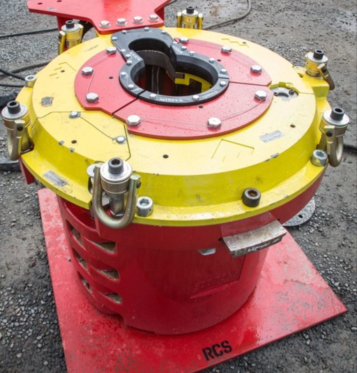
The C-375 Rotary Table by National Oilwell Varco is used for onshore and offshore drilling. Most conductor, riser, and wellhead elements will pass through the C-375 Rotary Table 37-1/2″ table opening.
Armco produces a full line of NATIONAL Rotaries notable for dependability, safety and efficiency, and suitable for any drilling requirement from shallow to the deepest wells. Construction features of NATIONAL Rotaries are developments of nearly half a century of constant design improvement.
Throughout every region in the world and across every area of drilling and production, our family of companies has provided the technical expertise, advanced equipment, and operational support necessary for success—now and in the future.
We believe in purposeful innovation because we see what others do not and we act. Through business innovation, product creation, and service delivery, we are driven to power the industry that powers the world better.
We believe in service above all because our singular goal is to move our customers’ business forward. This drives us to anticipate our customers’ needs and work with them to deliver the finest products and services on time and on budget.

The IADC Lexicon is © IADC. However, the documents from which the definitions were drawn may be copyrighted by the original sources, and may not be used without express permission of the copyright holders. IADC expressly recognizes the copyrights of contributors to this Lexicon, including API, OGP, ISO, NORSOK and DNV.
Jog the tilt axis from the positive travel limit to the negative travel limit. Make sure the A HOME SWITCH bit changes (on the Diagnostics INPUT 2 screen). If the bit does not change, replace the home switch.
Starting in software version 100.19.000.1120 when using P11, P12, and P13 parameters for T5C/Trunnions. There is an excessive rotation when the unit is commanded to zero return.
Go to the Haas Service Portal and download the latest configuration files. Update the rotary configuration files refer to the Update Rotary Configuration Files - NGC procedure.
Air leak/hissing sound coming from the motor enclosure. Motor enclosure ballooning out. Excessive bubbles are leaking between the side plate and the motor enclosure. Oil is leaking from behind the platter.
Install a 0-15 PSI pressure gauge on the enclosure cover. Do not actuate the rotary brake. Check the fittings, airlines, and pressure switch for a leak if the gauge reads any pressure. If the pressure switch is the source of the leak, replace the pressure switch and reseal the cover when reinstalling.
All of the XML objects in the configuration files need to have the tag "
Note: When replacing a pressure switch on an HRTSS, the brake must be bleed before use. AD0600 - HRT160SS, HRT210SS, and HRT310SS Brake Bleed - Instructions
Press[Diagnostics],then navigate to the Diagnostics---> MOCONtab and find "CH 4 [A] axis brake air pressure". Ensure the switch is reading the proper state of the brake and that it changes when it is actuated.
The shop’s air compressor is turned off at night, and air pressure builds up slowly after being turned on in the morning. This could cause O-rings not to sit correctly.
Add a ball valve and gauge to the airline going to the rotary. Close the valve before the compressor gets turned off, and open the ball valve after the compressor has been turned ON and the air pressure is higher than 85 psi.
Metal chips can damage the platter and brake O-rings if they get under the platter or break. Compressed air can push chips under the brake plate and the platter.
Do not use an air hose to clean rotaries around the platter. Instead, use a brush to remove chips around the platter before using coolant or air to clean up the rest of the chips.
Open enclosure/enclosures and activate and release the brake multiple times while inspecting fittings, air lines, pressure switches, etc., for air leaks. Fix the air leaks if any are found.
Machine with a TR/TRT unit set to an A/C configuration. The Y axis will position to the wrong side of the rotary centerline during DWO or TCPC operation.
Update the machine to the latest Software and latest Configuration files from HBC. A patch will no longer be required; this has now been fixed in the Configuration files.
Measure mechanical backlash at least every 90 degrees for HA5C and HRT at 0 deg, +- 90 deg for the tilt axis of TR and TRT units. If the unit is out of tolerance, contact your HFO for repair options.

Diversified offers a wide range of Manual Elevators such as Side Door Elevators, Single Joint Elevators, Slip Type Elevators, Safety Clamps and Rotary Slips for 2-3/8” diameter tubing to 30” diameter casing.
Side Door Elevators:Used for handling collar type casing, all of our Side Door Elevators are equipment with a safety latch lock. Our Side Door Elevators come in SLX 150-250 Ton variants from 4-1/2” to 30” OD.
Single Joint Elevators:The SJX Single Joint Elevator is designed for running single joints of tubing and casing from V-door to well center. Our inventory of SJX Single Joint Elevators range from 2-3/8” up to 30”. All comes with load tested Slings and Swivels.
Slip Type Elevators:Our Slip Type Elevators comes in HYC 200 Ton, YT 150 Ton and YC 75 Ton variants. With Slip and Inserts to accommodate 7” Casing down to 2-3/8” Tubing. We can also provide Low Penetrating Dies for Chrome running and handling applications upon request.
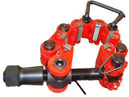
Safety Clamps:Used to secure flush tubular products during installation. Our inventory of MP series and Type “C” and “T” Safety Clamps are available from 2-3/8” to 30” OD. We can also provide Low Penetrating Dies for Chrome running and handling applications upon request.
Rotary Slips:Our inventory of Rotary Slips includes SDS, SDML, SDXL and CMS-XL variants from 2-3/8” to 30” OD. We can also provide Low Penetrating Dies for Chrome running and handling applications upon request.
Diversified also offers the following equipment to complete your Casing and Tubing Running Needs: Thread Protectors, Stabbing Guides, Drifts, Bowl & Slips, C-Plate)
Thread Protectors: We offer Air Operated or Clamp-on Type Thread Protectors to offer safe, reliable casing and tubing pin-end protection from 20” casing down to 2-3/8” tubing.
Stabbing Guides:Stabbing Guides are engineered to consistently align and safely guide two sections of pipe together through the use of specially formed polyurethane shells, thereby greatly reducing the chance of pin or box damage. We offer stabbing guides from 13-3/8” casing down to 2-3/8 tubing”.

The Kullenberg corer (Kullenberg, 1947; Kelts et al., 1986) is a single-drive, cable-deployed piston corer that is dropped into the sediment from a short distance (typically 0 to 3m), propelled by the momentum of the heavy (~1000 pounds/450 kg) lead weights on the core head. Cores are recovered in steel barrels lined with plastic tubes (standard polycarbonate for the CSD Facility system). The corer drop is triggered when a gravity corer, suspended on a second cable to the side of the Kullenberg corer, enters the sediment and ceases downward travel—thus most Kullenberg cores have an accompanying gravity core that captures the upper sediments that are disturbed by the long corer. Deployed from a cable, the range of water depths is limited only by the length of cable on the winch. However, the immense weight of the system requires a substantial secondary apparatus to handle the corer. A heavy-duty winch and hydraulic system or power supply must be employed to raise and lower the corer, and if long core barrels are used to increase the depth of recovery, a tower or A-frame must be available for deployment and recovery. The weight and bulk of the system can also create hazardous conditions in any deployment circumstances, but particularly if waves cause the vessel to roll and pitch. Thus, a minimum of two experienced crew plus three additional hands is required for safe operation.
The R/V KRKII is a large platform consisting of two 19-foot (5.5m), 950-pound skiff boats bolted together with aluminum deck plates and beams. It can be disassembled and towed behind a heavy-duty truck or shipped in a standard 20-foot shipping container. It was engineered and custom-built for Kullenberg coring, for which it provides a large, stable work surface, a 6.5m quad-leg tower, and 5m long moonpool. At 6m long and 5.5m wide, it is larger and heavier than is necessary for most other types of coring operations, and it is more difficult to ship and requires more time to assemble than more appropriately-sized platforms


 8613371530291