
how does a rotary table work manufacturer

A rotary table is a precision work positioning device used in metalworking. It enables the operator to drill or cut work at exact intervals around a fixed (usually horizontal or vertical) axis. Some rotary tables allow the use of index plates for indexing operations, and some can also be fitted with dividing plates that enable regular work positioning at divisions for which indexing plates are not available. A rotary fixture used in this fashion is more appropriately called a dividing head (indexing head).
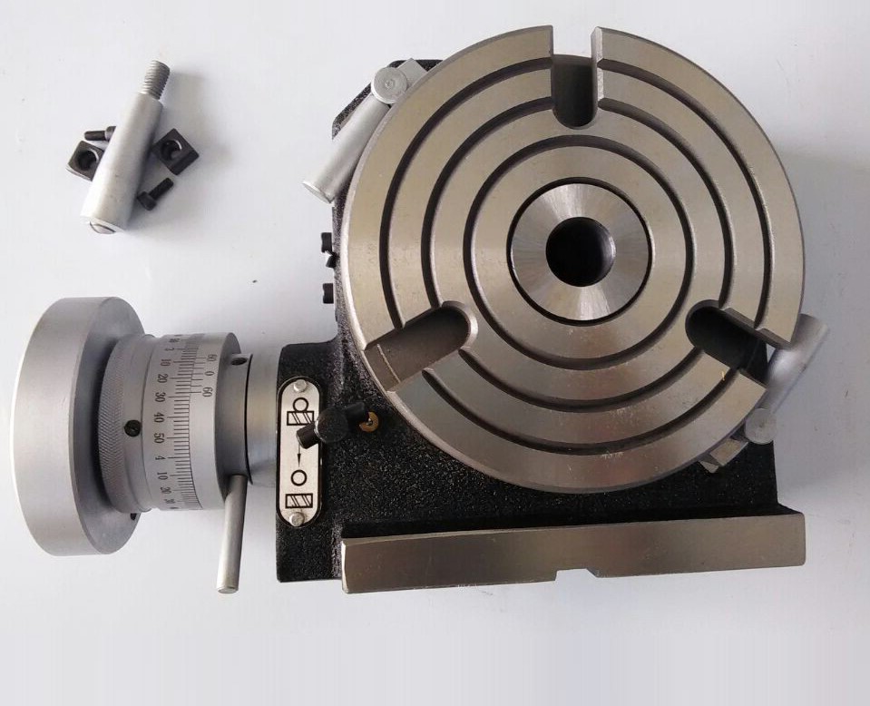
The table shown is a manually operated type. Powered tables under the control of CNC machines are now available, and provide a fourth axis to CNC milling machines. Rotary tables are made with a solid base, which has provision for clamping onto another table or fixture. The actual table is a precision-machined disc to which the work piece is clamped (T slots are generally provided for this purpose). This disc can rotate freely, for indexing, or under the control of a worm (handwheel), with the worm wheel portion being made part of the actual table. High precision tables are driven by backlash compensating duplex worms.
The ratio between worm and table is generally 40:1, 72:1 or 90:1 but may be any ratio that can be easily divided exactly into 360°. This is for ease of use when indexing plates are available. A graduated dial and, often, a vernier scale enable the operator to position the table, and thus the work affixed to it with great accuracy.
Rotary tables are most commonly mounted "flat", with the table rotating around a vertical axis, in the same plane as the cutter of a vertical milling machine. An alternate setup is to mount the rotary table on its end (or mount it "flat" on a 90° angle plate), so that it rotates about a horizontal axis. In this configuration a tailstock can also be used, thus holding the workpiece "between centers."
With the table mounted on a secondary table, the workpiece is accurately centered on the rotary table"s axis, which in turn is centered on the cutting tool"s axis. All three axes are thus coaxial. From this point, the secondary table can be offset in either the X or Y direction to set the cutter the desired distance from the workpiece"s center. This allows concentric machining operations on the workpiece. Placing the workpiece eccentrically a set distance from the center permits more complex curves to be cut. As with other setups on a vertical mill, the milling operation can be either drilling a series of concentric, and possibly equidistant holes, or face or end milling either circular or semicircular shapes and contours.
To create large-diameter holes, via milling in a circular toolpath, on small milling machines that don"t have the power to drive large twist drills (>0.500"/>13 mm)
with the addition of a compound table on top of the rotary table, the user can move the center of rotation to anywhere on the part being cut. This enables an arc to be cut at any place on the part.
Additionally, if converted to stepper motor operation, with a CNC milling machine and a tailstock, a rotary table allows many parts to be made on a mill that otherwise would require a lathe.
Rotary tables have many applications, including being used in the manufacture and inspection process of important elements in aerospace, automation and scientific industries. The use of rotary tables stretches as far as the film and animation industry, being used to obtain accuracy and precision in filming and photography.
rotary filing—that is, running a circular cutter withfile-like teeth in the headstock of alathe.Rotary filling and later,true milling were developed to reduce time and effort
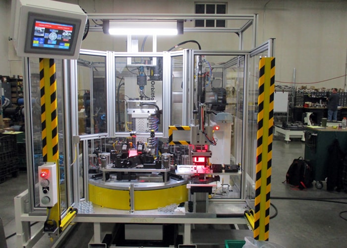
Indexing tables are used in a multitude of industries and in numerous applications. Their design is optimal for many manufacturing jobs, and they are a critical component in most automated manufacturing systems. Indexing tables are best defined as a machine tool positioning device. They carry components in a manufacturing environment with a repeating process of indexing (rotating) around an axis, stopping, dwelling while an operation is performed, then indexing again to repeat the process. They are usually made of circular steel plates, with one or more spindles, a drive system, encoders, sensors, controllers and slots or mounting holes to hold components.
Virtually any manufacturing operation can be performed on a part held by an indexing table including welding, grinding, drilling, assembly, painting, inspection, testing and more. In order to maximize operational efficiency, the machine doing the operation must also be built for the same intended application as the indexing table for them to work in synch. Similarly the machine that loads the indexing table with parts must also be synchronized. They must have the same capacity and be able to manage to the same dwell time for the system to work.
If the timing of these machines are coordinated, the time to operate on or assemble a product can be a fraction of that of workers assembling a product.
Industries that use indexing tables include automotive manufacturers, bottling companies, microchip manufacturers, pharmaceutical makers, consumer products companies and many more. They are invaluable to manufacturers pushing for automation and increased efficiency in their factories, turning work that used to take days into work that takes only hours. If a simple assembly task is required on small parts in a factory, there is no better way to complete the task than by coupling an assembly tool and an indexing table.
Programmable Rotary Tables have a multitude of applications in a wide variety of industries. They are used to position components that need to be rotated in specific, very accurate degrees of rotation so that manufacturing operations can be performed. Programmable rotary tables can be used to position parts for welding, machining, assembly, inspection or any number of operations requiring components to be presented at precise angles.
Traditional rotary index tables are positioned using mechanical components called ‘cams indexers’ in order to repeatedly rotate the table into a precise position. The cam indexers provide precise positioning to position a load using a mathematical motion curve that is machined into the cam. The mechanics provide a smooth and highly repeatable motion.
These tables are ideal for consistently delivering components to a fixed and repeatable angular position. They work well for applications that require high precision positioning at a lower cost. A traditional rotary index table may have very limited control functionality, perhaps using a sensor to determine where the indexer is along its rotational cycle. The sensor might be used to stop and start the cam motion in order to increase or decrease the ‘dwell’ period that occurs between rotary motions. This is a relatively inexpensive form of ‘programming’ a rotary index table.
An alternative to the traditional rotary index table is a programmable rotary table. A fully programmable rotary table uses a servo motor as the drive motor. A servo drive motor and programmable control system offer up nearly infinite indexing possibilities.
A simple application for a programmable rotary table is when an operation may require different or extended dwell times. A programmable rotary table enables a feedback system that allows the table to progress when an operation is satisfactorily completed.
A more advanced application for programmable rotary tables is when multiple products are run across the same production line. Having the ability to program the rotary motion of the table enables any number of product profiles to be run on the same machine, saving significant capital costs vs having to purchase multiple rotary index tables.
It’s important when selecting a rotary table to work with a company that has extensive applications engineering expertise. Matching the cam type, the drive and control system and the mechanics of the table to ensure that the system will perform with the moment of inertia of the component being handled, the cycle times and long-term durability of the table is vital.
A CNC rotary table is the precision positioning accessory that can provide a reliable 4th axis or even 5th axis for modern machining centers. Utilizing a computer-controlled rotary table can turn the original 3-axis machine tools into 5-axis CNC machines, expanding the accuracy as well as decreasing the costs while performing complex machining operations at one time.
A CNC rotary table is the precision positioning accessory that can provide reliable 4 or even 5 axis cutting operation capabilities for modern machining centers. Utilizing it can turn the original 3-axis machine tools into 5-axis CNC machines, expanding the accuracy as well as decreasing the costs while performing complex machining operations.
Rotary tables typically have rigid frames and coatings, and also excellent torque capacity, which makes the small device flexible and effective for a wide variety of turning, milling, drilling, and more metalworking operations. The easy setup and seamless interface allow the operators to easily add the rotary table to fit their 4-axis or 5-axis applications. .
The working principle is similar to the basic rotary tables, which is to support the workpiece by accurately rotating the workpieces on the axis in order to locate the parts for high precision tooling. Under rapid rotation, which is driven by CNC instructions, the cutting tools of larger machine tools or machining centers can remove the material and add the feature to the products at exact intervals. On rotary tables, there are vertical and horizontal axes for various tools to perform these high-performance metalworks. To enhance the accuracy and flexibility, there are models that employ additional dividing plates and come with additonal material handling mechanisms and features.
Since 4-axis and 5-axis machining is increasingly popular today, adding the CNC rotary table as the 4th axis is an ideal solution to easily open up more complex machining options at a lower cost. Due to the arrangement, they are widely also called the 4th or 5th axis or tilt rotary. The 4th axis, which is the rotational operational direction, is added to the original three linear axes which are known as X-axis, Y-axis, Z-axis. In some cases, there are two rotational axes add to the original 3-axis machining center, achieving utmost accuracy as well as effective multiple face cutting to reach the difficult area on the surface. Rotary tables are usually mounted parallel to the ground or the bed, with the platter rotating around the vertical axis, for example with the most common vertical milling machine combination. Sometimes the machining application requires an alternative setup with the table mountet on its end so that it rotates around the horizontlal axis. Often, a tailstock is used in this configuration. Virtually all models today come with a clamping kit to mount it onto the bed of your machine tool.
The function of the high precision rotary table is also to rotate the workpiece so the cutting tool can create the contour we desired out of the workpiece. However, a rotary table with higher precision has the ability to achieve great accuracy just as its name implies. There is also a major misconception between the resolution and the accuracy.
A common example is that if a digital readout displays to four decimal places, then the high precision rotary table must also be capable of achieving the accuracy to that same value. Even though for higher accuracy to be achieved, the resolution has to also be high, but there is no guarantee that the accuracy is going to be high. The accuracy is the concept which is the difference between the actual position and the position measured by a reference measurement device. The feedback mechanism such as the rotary encoder, and the drive mechanism can influence the accuracy of the advanced rotary table.
A CNC rotary table can provide great rigidity for stable machining operations. It consists of the worktable where the metal parts are held, the rigid bearing that withstands the forces and loads during the rotation, the solid base which is used for attaching the rotary table to the machining center or other equipment, the motor, and the CNC system.
The worktable is the tooling surface where the workpieces are machined after accurate positioning. The worm gearing is the core mechanism of the table, which mesh with the steel worm which is submerged in the lubricants. Both the rigid bearings and the worm gears have large diameters. Excellent concentricity is the key to smooth operation, durability, and most importantly, accuracy. Driven by a computer and electric motor, the worktable can position the materials at exact intervals. For more flexible or critical operations, dividing plates can be added to this component.
A CNC system regulates the simultaneous 4-axis motion of the rotary table. The instructions are programmed and transmitted via CAD software, reducing the time for adjustment and monitoring by human workers.
The type and size of the electric motors utilized in can define the router accuracy as well as the efficiency of the device. Servo motor and stepper motor are two typical types that can be divided into more subtypes. The servo motor uses a closed looping variable circuit, the circuit will constantly run to keep the function. The brushes must be replaced every 2000 hours of operation in the servo motor. Compared to stepper motors, servo motors are more efficient in power consumption. On the other hand, the stepper motor has a simpler setup which are the wires that are attached to the driver. The bearing of the stepper motor is the only wearing component. However, the stepper motor consumes a great amount of energy.
There are currently several different types and models available in the industries. Each of them possess its own traits and abilities. Let us take a look at the most common ones other than standard three axis tables
The 4 axis CNC rotary table will process the workpieces by holding them in the same position while the cutting tool performs along the XYZ plane to trim away the unwanted material. In general, a 4 axis model is very versatile equipment that can be used for several different industrial processes such as engraving curved surfaces, continuous cutting, and intermittent cutting. Besides, people can also add other devices such as cam machining, blade machining, and helical grooves to the 4 axes rotary table. Such a feature is simply impossible to achieve with the machining center which has only 3 axes.
Besides the 4 axis ones, there are also 5 axis models. They have the ability to allow the workpiece to be processed automatically from five sides at one time. people usually utilized the 5 axes rotary table in the industries such as the automobile, the aerospace, and the boating industries. The reason that the 5 axes rotary table is commonly used in heavy industries is that the 5 axis machining is an important technique to be used when the components need better intricacy and quick precision. All of these have more than three axes are called the multi-axis rotary table.
The installation method of the precision rotary table can be horizontal, vertical or inverted. When installed horizontally, the workbench surface is in a flat, vertical and horizontal position. When installed vertically, a rotary table is installed so that the surface of it can run up and down. In the reverse layout, itcan be rotated upside down in a horizontal position. The location of the drive of the rotary table can depend on the mount. The drive can be placed on the back, below, on the top or on the side.
When mounted horizontally, the spinning table top drive is positioned above the table floor. When the rotary table is horizontally placed, the side-mounted drive is located on the edge of the table board. The driving mechanism of the rotary table may be manual, electrical, pneumatic, hydraulic or non-driven. For manual revolving workbenches, release the workbenches and manually spin the workbenches with the crank.
Workpieces are gathered and machined through PC and fully programmed instructions. The 5-axis simultaneous operations will be measurably more reliable than products machined via different technologies. Also, the setup is simple and provides an indistinguishable process in every production cycle, the consistency of the quality of the metal products can be ensured under critical control and precision cutting.
Since the metalwork is driven by software, the preferred frameworks can be programmed and adapted by the rotary table. Saving both the cost and the room makes themis the ideal solution for potential users who don’t want to install larger equipment and new machines which may take up a great room for a wide variety of machining applications.
Another benefit is the utmost movements can be completed precisiely and faster. There are more favorable positions, operation angles as well as accessible machining that can be achieved through the technology. The complex operations are suitable for blade, helical grooves production, and other applications required to add complex features or require critical inspection in machining processes like the manufacturing of aerospace, automotive parts, and scientific equipment.
Addding a rotational table saves time because the extra finishing jobs or other sub-operations can also be performed at one time in the machining center.
A rotary table can be used in many applications including manufacturing, inspection, and assembly. Indicators are used, for example, for assembly, manufacturing, and bottling equipment. They typically use a single item in workspaces or move relatively small layouts of items around stations for sequential work or assembly.
In automated assembly machines, the rotary tables implementation is widespread, and choosing the right mechanism is important for both improving efficiency and reducing the cost of this vital component. This guide discusses two common devices for rotating indexing and offers guidance on the right range. There are several ways to get mass mobilization when it comes to the development of rotary indexing tables. Regardless of whether the load or load in centuries of thousands of kgm2 is incredibly light. When choosing a robust rotary index solution that will match or meet your standards, there are several factors to take into account when spinning, elevating, or pushing.
When determining the influencing factors on the postitioning accuracy, the first thing to look at is the mechanical properties of the table itself. A rotary table contains six degrees of freedom. Each of these movements increases the total risk of positioning errors. Usually, a rotary table is driven by a worm gear, which is connected to the motor through a rotary encoder on the back. The position of the table can be determined by the number of pulses transmitted from the encoder to the control device.
The four main sources of error due to the semi-closed position loop are geometric errors, thermal deformation, elasticity, and wear. The sum of these errors is called angular positioning error. To greatly reduce the angular positioning error, the ideal position for installing the angle encoder is on the rotating shaft under test. The angle encoder is installed under the rotary table, and the rotary encoder is installed under the rear motor, the position loop is now considered a closed-loop system.
Precision is a relative term. About a quarter of an inch is great and will meet the accuracy of its application. Others, for example, require micron-level accuracy in measuring and indexing devices. Then, some applications fall within these extreme ranges.
The misunderstanding is that you may have used an inaccurate indexing device and made it accurate by introducing a pin or wedge locking device. These devices increase the complexity and cycle time of use, and when they are used together with a high-precision positioning device, they may cause damage and reduce accuracy.
In the actual test, by selecting specific components, motion index drive, servo rotary indexer, the measurement accuracy is as high as 5-6 microns. These are not the results approved by Motion Index Drives, but the results of customer certification. When starting and stopping large amounts of data, it is important to know how fast it takes to stop the application with large amounts of data.
In a less rigid environment or the presence of higher recoil, a faster start and stop will bring many control problems. When moving masses (whether rotating mass or linear mass), starting and stopping in a system with a backlash of several arc minutes will cause a lot of back and forth movement in the gear system. The result is a force that is difficult or even impossible to calculate. In addition, when the gear head is used in rotating applications, the farther the mass is from the center of rotation, the greater the backlash. In applications with very slow deceleration times, recoil may not be a problem.
Backlash in the positioning process is a big issue – when it comes to the beginning and stopping volumes, it"s crucial to know how quickly you need to avoid the mass of your rotary indexing table applications. In a less rigid system or where there is an increased backlash, quicker start-ups and stops can cause a lot of control issues. When shifting a mass, whether rotary or linear, starting and stopping in a system with several minutes of backlash arc will create a lot of back-and-forth motion within the gearing system. The effect is a power that can be difficult and probably hard to quantify. In comparison, as the gear head is used for rotational applications, the more the mass is from the axis of rotation, the further the backlash is magnified.
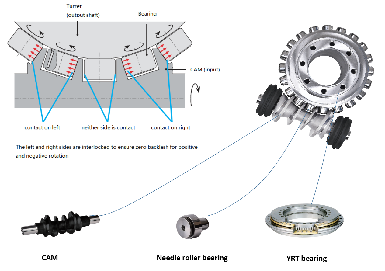
The backlash may not be a concern in systems where deceleration times are incredibly long. In the case of cam indexers, there is " Zero Backlash." The cam indexer and rotary table dynamics give an incredibly rigid, highly regulated framework. A modern cam indexer system is capable of withstanding short cycle times with stop times in milliseconds.
So you want to get the smart manufacturing going but are not sure of what to look for in rotary tables. The information provided in this section may be able to help. The primary factor is to determine the mass snapshot of inactivity. This is often overlooked when measuring a rotary table for the machine.
Another significant factor is the size of the workpiece being rotated, including how big it is and how substantial it is. You want your rotary tables to be large enough to handle enormous pieces. This is where tilling rotary tables may become handy so that the pieces can be handled without causing interior harm. They allow the quickening and decelerating of machining at appropriate rates.
The last factor is accuracy, the applications for which, for instance, pivoting a gigantic part to allow welding highlights on it where the individual stop positions can be genuinely free. On an additional note, when choosing direct drive rotary tables, factors that you should consider when selecting a rotary table for your CNC machinery include accuracy, backlash, mass moment of inertia, acceleration and deceleration, speed, and environment.
Indexing system use is commonly possible in automatic assembly machines and the right process is important for both performance maximization and cost reduction.
Cam indexers are an omnipresent tool used for several decades for rotary indexing tables. They are suitable for applications that often index the same angle and need a high degree of accuracy at a relatively low cost. To place the load, a cam indexer uses a mechanical cam. A math curve is pushed onto the cam and provides incredibly smooth and repeatable movement.
Another popular alternative is a fully programmable rotary index table. A rotary table is advantageous in two different situations. Firstly, a versatile movement pattern is important. An example is if two components are running on one computer, each of which requires different index patterns. For incredibly fast placement accompanied by a long period, another condition that matches the servo pointer is. The need to accelerate the camshaft while the cam indexing mechanism was operating before starting the output movement reduced the on-demand cam indexer. Acceleration of the camshaft is possible, but there is a delay before the movement begins. There are realistic restrictions.
With an indexing table, the output rotates as soon as the servo starts moving. This is not difficult for a continuous cam indexer or a zero-backlash servo indexer, but it can also be difficult for an on-demand cam indexer. For applications with high-speed servo indexing, smooth movements are crucial. A zero-backlash preloaded reducer can achieve this. The ideal alternative for correct positioning with high dynamic response would be the zero-backlash reel drive system.
Application parameters, like a moment of inertia, indexing angle, indexing period, and residence time, are required for each indexer style. The rotary indexing table for the application should also be sized correctly by a reputable manufacturer.
When it comes to powered rotary table, it is the rotary tables widely used in CNC machining center which responsible for precisely locating the parts in the commanded angle in order to perform multi-face machining at one time.
For starters, we need to know what a rotary table is. Rotary table is a high precision positioning device which is widely used in machining and metalworking. With the rotation, the operators can perform drilling, milling, cutting and other applications at exact intervals around the horizontal or vertical axis. To achieve the high accuracy and efficiency, many rotary tables can incorporate with index plates or dividing plates. With the help of additional components, the rotary tables can be used for indexing application or even position the work piece at divisions on the dividing plates.
When it comes to powered rotary table, it is the rotary tables widely used in CNC machining center which responsible for precisely locating the parts in the commanded angle in order to perform multi-face machining at one time. Originally, in a 3-axis CNC machining center, there are only X, Y, Z working axes. The X, Y, Z axis are the linear lathe axes. Operating along the XYZ planes, the Z axis is the important axis that is aligned with the main axis of the machines. On the same plane, the Y axis works in horizontal direction while the X axis is the vertical operation direction.
In typical machining centers that have the 4th axis, the 4th axis is the 180° rotation axis around the X axis. With a CNC motors, the motorized rotary tables can play the role as the 4th axis in the machining centers to enhance the flexibility of metalworking applications. The arrangement of involving powered rotary table in 3-axis machining center is popular for cam machining, helical grooves producing, blade machining and other unique profile machining. Powered rotary tables have a wide range of applications, for example, utilizing in both manufacturing and inspection stage of essential components in aerospace industry, automobile manufacturing and other scientific industries.
The vital elements of a powered rotary table include a supporting disc where the work pieces are clamped for machining, a solid base for clamping onto another larger table, machine, or machining center, the CNC controller and motor. A through hole is machined into the CNC rotary table to fit the Morse taper center or fixture.
The precision-machined disc is the rotating surface where the work piece is positioned and fixed firmly. T slots are the typical parts to help clamping the work pieces. The chuck is used to hold the work piece with a dial indicator to ensure the chuck and product are centered. After installing the chuck with bolts and T-nuts then checking if the work piece is centered, the operator can position the job on the table. The disc can spin freely under the instructions from CNC controller and motor. It is also the components which the indexing plate or dividing plate can mount with. When CNC controller and the CNC motor provide inputs, the rotation of the worm gear is activated and the mating gear mounted beneath the table surface begins to spin, either. The worm gears perform the precise rotations of the rotary table and every parts of the disc are critically calibrated in degrees.
The computer numerical controller transport programmed commands to activate the powered rotary tables. The commands are conveyed in CAD files, which refers to Computer Aided Design files, and provide sequential instructions to ensure the smooth operation. Eliminating the human power, CNC provides reliable and precise high performance positioning for further machining applications.
The size and type of the CNC motors can determine the routers precision, the efficiency and also the accuracy. Following is the basic introduction of two classes of motors used in CNC rotary tables, which are the stepper motors and the servo motors. Within these 2 classes, there are more subtypes.
Servo motors use closed looping variable circuit which continuously run for maintaining smooth motor function. The brushes on this type of CNC motors should be replaced after two thousand hours of operation. The encoders may need to be checked and replaced, too. Servo motors feature the efficiency in power consumption. They perform with about 90 percent of efficiency when giving light loads.
Stepper motors only require the wires that connected with the motor driver, having simpler setup. The only wearing part in this type of CNC motors is the bearing mounted on the motor, which slightly reduce the equipment life. Compared to servo type, stepper motors consume a large amount of power to provide the output, and much of them is converted to heat. Depending on the stepper driver, the stepper motors are often seventy percent efficient.

Rotary tables are positioning devices that are oftentimes used in precision manufacturing applications. More specifically, they are tools that hold parts on rotating axes, which increases productivity, accuracy, and repeatability. It seems simple enough, but there are various types of rotary tables. So how do you choose which one is best for you? Let’s go through three common kinds of rotary tables – air-bearing, oil hydrostatic, and mechanical-bearing – to assist you in answering that question.
In many cases, air-bearing rotary tables will be the answer. This is due to the fact that they have the capacity to run longer than other kinds. These are exactly what they sound like; with air-bearing rotary tables, parts float on air above the table. With this, there are no contacting parts to wear the machine down, resulting in decades of maintenance-free motion. That is a significant benefit to any piece of air-bearing equipment, but these rotary tables are specifically beneficial for certain applications.
Maximizing metrology productivity can be challenging, but utilizing air-bearings can assist in boosting turnover. Additional industries such as optics, assembly lines, and light machining and grinding, can use them to increase accuracy and productivity as well.
Similar to air-bearings, oil hydrostatic rotary tables do not have any contacting mechanical parts, as they float parts on oil. These rotary tables are most commonly used for grinding and machining when smooth and repeatable motion is a necessity. They provide high load capacity and can be useful when extreme stiffness is necessary.
Mechanical-bearing rotary tables are a bit different from the other two. Just as the name suggests, this type of rotary table does have moving, touching mechanical parts. And while this does sometimes result in a shorter life than the air-bearing or oil hydrostatic tables, many organizations will still pick these out of the others. Why? They still offer high performance.
These rotary tables can be used in most applications and provide superior performance in radial, axial, and angular error motions. In all, mechanical-bearing rotary tables do the job; however, it is possible that they will not last as long as other types.
The answer to the question, “Which one is best?” is the ever-hated, “It depends!” In general, air-bearing rotary tables will provide the highest accuracy for the longest amount of time. The lack of touching mechanical parts allows this type of rotary table to last decades. However, if you need a stiffer hold, oil hydrostatic could be the better choice. And in other cases, mechanical-bearing rotary tables could be best. All in all: It depends.
But if you want to know more about rotary tables and which would be the right choice for your application, contact the experts at ABTech. We will ensure you get exactly what you need.

At Rusach International,rotary table design, engineering and manufacturing & pallet system design, engineering and manufacturing is our specialty. We can supply rotary tables from 100mm up to 8 Meters in diameter. See our rotary table pages. We specialize in high accuracy, up to +/- 1 arc second, heavy load capacity, large work pieces, production style, heavy duty rotary tables and pallet shuttle/storage/transfer systems. We also have a line of standard small production tables that are very cost effective, yet can be customized per application.
Rusach International systems are not proprietary and therefore can be integrated into any machine, control system or application. We do not believe in “locking” a customer down with proprietary parts! We work with all the major industry control, motor and encoder manufacturers.

We combine rotary index tables with industrial automation systems so each task of your manufacturing process blends seamlessly into the next. For example, in the past we’ve created industrial automation systems that join rotary indexing machines with pick-and-place units for some of our clients. Contact us to see what we can do for you.
Rotary indexers are just one part of the equation when building a custom assembly cell. It’s important to remember the entire scope of the project and be cognizant that the rotary table should be able to move precise distances before stopping cleanly, with no backlash or wobbling. It needs to be balanced and capable of handling the tasks at hand.
Our automation experts have years of experience in consulting with our customers to create machines that suit their needs. We incorporate rotary tables from industry leaders like WEISS, Fibro, and Camco into our machines to create the perfect fusion of form and function. Our dedication to quality is unmatched in the world of custom machinery.
We seamlessly integrate rotary indexing tables into our automated machinery to provide you with custom solutions that work for your business. If you’re looking to take your manufacturing process to the next level, give the custom machine builders at Paramount Tool a call at (616) 582-5300 today. We’re always happy to answer any questions you may have about our rotary indexing machines or the machine building process as a whole. For a free quote, fill out our contact form and we’ll get back to you as soon as we can.

An indexing table is a rotary table device that uses indexing to position a workpiece. CNC indexing tables are invaluable in milling and other industrial processes that require high precision cutting and shaping. They have a wide range of applications, including machining, positioning, inspection, and automation.
In manufacturing, indexing is the process of exposing a new edge or surface for use. An indexing table is used to convey and position workpieces during a manufacturing process.
The table’s indexing unit rotates the piece a precise distance into a specific position. It remains in place while the manufacturing tool cuts or drills the workpiece. Once the operation is completed, the table indexes the next section of the workpiece into position.
Indexing tables have a wide range of features. A basic indexing tool consists of a precision-machined steel plate with slots or mounting holes to secure workpieces during the machining process. They have either fixed or adjustable indexing angles. Parts can be loaded and unloaded manually or automatically.
There are three types of mounting: vertical, horizontal, and versatile. Indexing tables come with one or more spindles. Drive systems can be powered by pneumatic or electric motors, hydraulic drives, or even manually.
An indexing table is one of the most efficient ways to move and position a piece for precision machining. They can be used with small, medium, or large workpieces. Some of the benefits of using an indexing table include:
CNC indexing tables are used in the machining process for parts and components in a wide range of industrial applications, including food and beverage, printing, aerospace, defense, construction, medical, and automotive.
CNC Indexing & Feeding Technologies has been a premier importer/distributor of quality machine tool accessories such as hydrodynamic magazine-style bar feeders, short bar loaders, rotary tables, high-pressure coolant systems, and oil skimmers since 2007. Our line of TJR Precision rotary and indexing tables turn any 3-axis machining center into a 4 or 5-axis with customized faceplates available. In addition, we offer manufacturers our own CNC Indexing brand of hydrodynamic magazine bar feeders, short bar loaders, and gantry-style autoloaders.
If you’re looking for the best CNC accessories for your manufacturing operations, contact CNC Indexing & Feeding Technologies online or call us at 513-770-4200.

Fig. 4—On this tilting rotary table, one servo controls rotation, another controls tilt. Both servocontrols are slaves to the CNC with RS-232 communication, providing five-axis capability from a standard three-axis CNC.
Fig. 1—Modern rotary tables such as this one from SMW Systems have large, widely spaced spindle bearings, large diameter wormwheels and built-in spindle brakes.
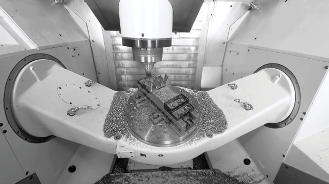
If you want to make parts similar to the complex valve body (upper left), an indexer using M-code, RS-232, or “full fourth axis” control is appropriate. Only positioning and rotary cutting moves are required. The center workpiece is a cam that requires simultaneous rotary and linear moves. You’ll need full four-axis control for such workpieces. If you want to do parts similar to the impeller on the right, the contour cutting will require simultaneous five-axis machining.
Many plant managers and shop owners dream of having the latest horizontal machining center (HMC) with all its features, benefits and sophisticated capability. While typical HMC features such as an automatic pallet changer and a 100+ cutting tool magazine are valuable, perhaps the most valuable characteristic is the HMC’s ability to machine on more than one side of the workpiece due to a built-in indexer or full fourth axis.
On complex workpieces that require machining on surfaces not 90 or 180 degrees from each other, indexing or fourth-axis rotation is almost essential to produce the piece. Even when rectangular workpieces with all surfaces 90 or 180 degrees from each other are put on a tombstone, the HMC’s built-in fourth axis of rotation creates a productivity advantage. This is true even if machining on more than one side of the part is not essential.
Any time you can increase the “run cycle,” do more cutting in one operation and avoid handling the workpiece, productivity goes up. Workpiece accuracy also improves. Unclamping and refixturing a workpiece to present a different surface to the cutting tool is always going to introduce some error.
The high cost of horizontal machining centers compared to the incredible values available today in vertical machining centers puts horizontals out of reach for many shops. Fortunately, today there are several suppliers of quality accessories that allow the VMC shop to equip its verticals with indexers, fourth axes and tombstones. These add-ons really work and give many of the benefits of an HMC at a fraction of the price.
Earlier rotary tables and indexers didn’t have the accuracy, rigidity or control flexibility of today’s models. Many shops that tried using indexers in the past had been disappointed in the performance of the older models and abandoned their use in favor of multiple operations, multiple holding fixtures and multiple handlings of the workpiece. They decided that the manual, multiple-operation process was better than trying to use ineffective early model indexers and rotary tables. Today, the situation is different. Manufacturers now offer units that are very accurate, very rigid and have a variety of control and interface options.
The best indexer and control system for you depend on the work you need to do. As with most things, different designs compromise certain capabilities to gain others. Unless you understand these trade-offs, you are at risk of selecting something other than the best system for your requirements. Let’s see what’s available, review the differing capabilities and discuss the advantages and disadvantages of each design. Once you understand the options, you can evaluate them against your requirements and then consider prices and suppliers.
Of course, such a system does not exist. Add the “lowest price from the supplier that gives the best service and support” component and it probably never will exist.
Terminology in the area of indexers is not standard. Terms such as fourth axis, indexer, rotary table and so on are used interchangeably by different machine tool and accessory companies. So, when selecting and buying, you must ask a few questions before assuming you know what you’re going to get. Also, beware of terms such as “precision,” “high precision,” “accurate,” and “rigid.” Is the “brake torque” specification some absolute break away spec or the torque at which some “unacceptable” amount of rotary deflection occurs? Is the “ten arc seconds” accuracy specification certified every one degree, or is it inspected only every 15 degrees? There are no industry standards for specifications and testing. So ask questions and deal with a supplier in which you have confidence, or buy with a guarantee of performance to make your parts.
We’ll start with the mechanical hardware and discuss the electronic control options later. There are at least three common mechanical indexer/rotary table types.
These tables provide infinite positioning as well as the possibility of rotary cutting. A servomotor controlled directly either by the CNC or by a secondary servocontrol rotates a wormscrew, which drives a wormwheel on the rotary table spindle.
The absolute position accuracy of these systems is a function of the quality (precision and accuracy) of the wormgear set (wormscrew and wormwheel), the accuracy and resolution of the servosystem, and the means of servoposition feedback. Most of these servosystems utilize an encoder to monitor the position of the motor rather than the rotary spindle directly. To eliminate any inaccuracies in the wormgears and servo system, some high-end systems use a glass scale or other encoder directly on the rotary spindle to monitor actual rotary spindle position. Figure 1 (at right) shows a typical wormgear rotary table cross section.
If controlled directly by the machine tool’s CNC, they are most commonly referred to as a “full fourth axis.” A full fourth axis has the advantages of having only one CNC program, no programming required by the operator on the shop floor, minimum chance of a crash due to operator error, and the ability to make simultaneous rotary and X, Y or Z moves to do true helical milling operations as required by some more exotic workpieces.
Claims of position accuracy are often misleading since there are no industry standards. Although some manufacturers test and certify absolute position accuracy every one degree, most do not state exactly what their specification means.For all except those few expensive systems with glass scales directly on the rotary spindle, any accuracy specification is for a new table before it has been subjected to any “crashes,” which are not uncommon. Even seemingly small crashes can damage wormgear sets.
Typical infinite positioning wormgear systems utilize a friction brake to hold position against cutting forces. When cutting forces are applied directly on the rotary spindle centerline, friction brakes are generally adequate for most work. However, when cutting forces are applied to workpieces far off centerline, such as on the edge of a part on a tombstone fixture, the resulting torque on the rotary spindle can cause it to deflect. This result is especially likely when heavy cuts produce high thrust forces.
These indexers offer discrete positioning only. Depending on the number of teeth on the face gear, the minimum increment of index might be 15 degrees, 5 degrees or 1 degree. Whatever the minimum increment, only workpieces with angles representing some multiple of the minimum can possibly be machined.
Face gear mechanisms used in indexers are similar to those most commonly found in the turrets of CNC lathes, which by function must index very accurately and very rigidly to withstand the high cutting forces the lathe turret encounters. Face gear mechanisms generally fall into two categories, the two-piece and the three-piece design. Two-piece designs require the face plate of the indexer to “lift” to disengage the face gears. Three-piece designs maintain the same accuracy and rigidity of a two-piece without the need to “lift” the faceplate. In Figure 2 (at right), note the massive face gear that locks the indexer spindle in position.
Assuming it’s a quality face gear set, absolute position accuracy is superb and is maintained for the life of the indexer almost in spite of any “crashes” that might occur. Units with true absolute angular position accuracy of 5 arc seconds or less are available. These units are ideal for the highest precision work such as line boring half way from one side, then indexing 180 degrees and line boring half way from the other side.
Some face gear systems use a servodrive to achieve approximate position and then rely on the face gear for final accurate positioning. These systems are bi-directional and fast. Any random move can be programmed with one simple command. Some other systems use a pneumatic piston to rotate to the approximate position. Typically, these systems rotate only in one direction. All moves must be equal and may require a pause to utilize more then one M-code signal to achieve position. These work but can be tedious to program, set up and operate. They are more prone to crash due to operator error then servodriven units.
These indexers are becoming a thing of the past. They have all the disadvantages of the pneumatic piston driven incremental face gear indexers. Plus, compared to face gear units, they are neither particularly accurate nor rigid. Index positions are usually limited to 15-degree increments. Position is controlled by a pin in a hole or more often by a dog in a notch on the outside of a ring.
Whether you select an infinite positioning wormgear rotary system or a facegear system as the best mechanical design for your work, your next decision involves how you will control the rotary axis.
With a pneumatic incremental indexer, you probably will have no choice. Your machine’s CNC will control the indexer by communicating with a special indexer control via an M-code.
If you select a system with a servodrive, you have three choices: 1.) direct “full fourth axis” using only the machine’s CNC, 2.) an M-code command from the CNC to a separate rotary control, or 3.) RS-232 communication between the machine’s CNC and a separate rotary control. Each of these choices has advantages and disadvantages.
A single, four-axis CNC is the easiest to use and provides the most control. Four-axis CNC is best for certain kinds of workpieces. Full four-axis control systems are usually ordered for delivery with a new machine. Systems can be retrofitted; however, retrofitting is complicated and expensive. The advantages of a single four-axis control are numerous, and the disadvantages are primarily related to cost.
The single CNC constantly tracks all three linear axes (X,Y,Z) and the rotary axis. This provides the ability to do precise helical cutting with simultaneous rotary and X, Y or Z moves.
While a few machine builders offer a full four-axis control with rotary table for about 10 percent of the base price of the machine, most charge more than 20 percent.
Very few machine builders make it easy to retrofit a full four-axis rotary table. For most builders, retrofitting is a complicated process, and the cost typically exceeds 30 percent of a base machine price.
The motor for the rotary axis must be matched to the servodrive of the CNC. Because cable connections are not standard from one machine builder to another, rotary tables can not generally be used on more than one machine.
Some applications may require the accuracy and rigidity of a face gear system. However, many machine builders don’t offer face gear systems with a full four-axis control, although such systems are feasible.
An M-code actuated system provides a fourth axis of motion by combining a standard three-axis CNC with a rotary table or face gear indexer that has its own separate rotary servocontrol. The rotary program is entered and stored in the separate rotary servocontrol. The CNC communicates with the rotary control via an M-code. When the rotary control receives the M-code signal, it executes the next rotary move stored in its memory, then sends a signal back to the CNC, telling it that the move has been completed.
Typically, the rotary program includes many separate rotary moves. One move might be a simple index to position at full rapid speed. Another might be a slower rotary move to machine a groove or other feature on the workpiece. Figure 3 (at right) shows a typical rotary servocontrol system.
High quality M-code controlled systems are available from several suppliers for a price of about 10 percent of a base machine price. (For example, a 5C rotary system at $6,000; a 6-inch faceplate system at $7,000; a 9-inch system at $10,000; and so on).
Requiring only one M-code, 110V power and an air line for operation, these systems can be retrofitted to almost any CNC machine, typically with less than a day of downtime.
Systems can be moved from one machine to another as long as the next machine can issue M-codes. A shop with multiple machines and multiple rotary systems can select the best system for each job regardless of the machine. For example, a small indexer can be used for small parts to avoid cutting tool interference problems and to minimize indexing times. A big indexer can be used for big parts. A face gear indexer can be used when the maximum in accuracy and rigidity are needed and the work can be accommodated by multiples of 5 degrees of index.
The machine operator needs to enter the rotary program into the rotary servocontrol, or select the right program if it’s already stored in the rotary control’s memory. This takes some time, and there is the chance of an error.
If the machining cycle is ever interrupted in mid-cycle, such as to inspect a workpiece feature or replace a worn cutting tool, the operator must be sure to back up the rotary program and the CNC program to a point that keeps the two programs in sync. This step can be confusing, and any error can result in a “crash,” with a cutting tool coming down to a workpiece rotated to the wrong position.
Although it is possible to perform simultaneous rotary and X, Y or Z moves, they are not recommended. If you have patience and can afford to scrap a few parts, you can use trial and error to find the right rotary speed to match the linear move and determine starting points that match.
Recently developed, RS-232 communication between a three-axis CNC and a rotary servocontrol offers advantages of full four-axis and M-code operation. RS-232 is the commonly used, standard electrical interface for connecting peripheral devices to a computer. Personal computers often use the RS-232 communication protocol to send information to a printer. Another common use for RS-232 communications is connecting a PC to an external modem.
Nearly all CNC units have an RS-232 port, and it is commonly used to exchange CNC programs between a computer system and the CNC. More recently, RS-232 connections have been used by CNCs to communicate with robots and rotary tables. To communicate with the rotary table’s control, a special line of code is inserted into the CNC program. This line of code sends a string of numbers and letters through the RS-232 port to the rotary table control, which translates the string of code into rotary moves.
RS-232 communication between a three-axis CNC and a rotary servocontrol provides much of the best of both worlds of full four-axis and M-code operation. Both the linear and rotary moves are stored in the CNC as part of the workpiece program. When a rotary move is required, the CNC sends the commands for that one move (rotary speed and angle of rotation) through an RS-232 line to the rotary control.
The rotary control executes that one move and sends back a signal to the CNC, indicating that this move has been completed. The CNC then commands its next linear move. The separate rotary servocontrol simply works as a slave to the CNC. The machine operator turns the rotary control on in the morning and does not need to attend to it the rest of the day. Figure 4 (at right) shows a tilting rotary table system utilizing two rotary servocontrols with RS-232, providing five-axis capability from a standard three-axis CNC.
Crashes are nearly as unlikely as with a full four-axis control. The correct rotary program is always selected because it is part of the total workpiece program stored in the machine’s CNC. Note: Rotary moves should be programmed in “absolute position” so that if the machining cycle is interrupted, the operator can back up the CNC program to just in front of a rotary move, then safely resume the program.
Retrofitting is easy provided the machine’s CNC has an RS-232 port and appropriate communication software, which may already reside in the CNC or be available from the machine builder.
With RS-232, two rotary controls can be operated by most three-axis CNCs with only one RS-232 port. Five-axis capability with a tilting rotary table setup can be retrofitted to a three-axis machine for about $25,000 (a new, full five-axis VMC option is typically priced at $95,000).
Both the work you need to do and the machines you own or intend to purchase will influence what you select for a rotary axis. These guidelines summarize what you should consider.
When buying a new machine, get prices on everything the builder offers, no matter what kind of workpieces you’ll be machining. If the builder offers a full four-axis system with a high-quality, infinite-positioning rotary table at a price of about 10 percent off the base machine, this system will probably be your best choice.
If your workpieces can take advantage of the accuracy and rigidity of a face-gear system, and you can live with the 5-degree minimum increment, a face gear system controlled by RS-232 or M-code is a good choice. A few builders offer a face gear system with true four-axis control.
If you’re doing a variety of work that requires simultaneous rotary and linear helical moves, you’ll probably want a true four-axis system regardless of the cost. However, you should consider a more economically priced RS-232 or M-code system when you are retrofitting an existing machine and have only a couple of jobs requiring these moves, especially if these jobs are long run and you can afford some extra programming and setup time. These systems are worth considering if you simply can’t afford the price of a true fourth axis.
If you’re retrofitting existing machines, especially if you have several and want to do rotary work on more then one of them, check with the builder on the cost of upgrading to full four axis. You may conclude that the cost and flexibility advantages of RS-232 or M-code will make one of them the best choice.
Adding a rotary axis to a VMC is worthwhile whether you want to do full four-axis simultaneous machining of exotic workpieces, simple indexing of parts that need machining on surfaces not at 90 degrees from each other, or tombstone processing of rectangular parts that benefit from a longer unmanned machining cycle. Today, many good options exist. If you’re buying a new machine, have the builder quote the optional systems it offers. If you’re going to retrofit an existing machine, contact either the original supplier or the companies that offer complete indexer and rotary table systems. Retrofitting is highly affordable. (Systems from SMW Systems, for example, generally cost a little over $1,000 per inch of faceplate diameter, including installation and training.) MMS
Mitee-Bite Products’ fixtures demonstrated their powerful clamping support in a project with Akron Gear & Engineering to vertically hold a 1-ton ring during machining.

Mr. Straessle is pL Lehmann product manager at Exsys Tool. He says that while five-axis machines have become more affordable, they still can be two to three times the cost of a three-axis VMC, depending on the model. Therein lies one advantage to rotary tables, which, when installed on the bed of a three-axis VMC, combine a rotational C axis and a tilting A axis to enable the machine to perform either five-axis positioning work (aka 3+2 machining) or full five-axis contouring. Three-axis VMCs outfitted with two-axis rotary tables are commonly smaller than five-axis machines, too, saving valuable floor space. Unfortunately, they also tend to have tighter work envelopes, meaning a sizeable rotary table will be more restrictive of a machine’s movements.
A compact rotary table preserves work envelope space, providing more room for spindle and tool movement. Plus, shops have the option to use just the rotary table, mount standard vises next to it or remove the rotary table altogether, which is made simpler when the rotary table has a zero-point-type locating system to eliminate the need for alignment when it is removed and then remounted.
That said, Mr. Straessle says compact rotary tables still must possess design elements that enable them to perform effectively for a range of work. Here, he details four such features inherent to the pL Lehmann 500 series of modular-designed rotary tables, available in North America through Exsys Tool.
1. Load capacity. The compact 500 series provides load capacities that, in the past, were only available with larger rotary tables. For instance, the 3-inch rotary tables in this series are generally half the size of comparable units, but can handle workpiece loads as heavy as 400 pounds, he says.
2. Speed and torque.Rotary tables commonly use either direct-drive or gear-driven technologies, the former able to achieve high rotational speeds and the latter offering high torque. The 500 series uses the company’s pre-loaded gear drive (PGD) design, which is said to offer the best of both worlds in terms of high speed and high torque while being as much as four times as rigid as direct-drive systems. Plus, it enables the rotary tables to generate rotational speeds as fast as 160 rpm with virtually zero backlash.
3. Spindle clamping power.Once a rotary table is oriented to the desired position, an effective spindle clamping system is needed to securely hold that position during machining operations. Some rotary tables use an external intensifier or some other type of standalone hydraulic unit combined with disc braking to achieve necessary clamping forces. Conversely, the 500 series features an integral unit that converts air pressure into hydraulic holding power, using a
cylinder/piston mechanism that requires only 90 psi of air pressure to generate more than 3,000 psi of hydraulic clamping pressure to firmly clamp the spindle in place at any position around its 360 degrees of rotation. In addition, this air-over-oil clamping system can often achieve unclamp-to-clamp times of less than 0.4 second as compared to the multiple seconds external systems typically require.
4. Monitoring system.The 500 series features a self-contained, internal monitoring system used to track and record vital rotary table information, including temperature, rotational speed and clamping force. It also detects internal pressure decay.
In addition, the rotary tables have USB ports to enable users to download monitoring data to log the operational history of the table. Not only does this data highlight crashes or malfunctions, but it also facilitates more effective preventive maintenance by offering early warnings to possible issues so users can avoid unplanned downtime. Plus, the monitoring system activates a series of LED warning lights when it recognizes a potential problem. For example, a blinking orange light is an alert to a situation that can be addressed before it becomes serious, while a continuous red light means immediate attention is needed. Because these rotary tables integrate with all the common machine tool CNCs, users can have warnings displayed on the control screens, too. By connecting a laptop running software such as pL Lehmann’s TeamViewer, users can also solicit assistance via the Internet from a company technician who can log on to assist in troubleshooting.
Mr. Straessle says the company guarantees the spindles on its standard rotary tables to achieve runout of 5 microns and its high-accuracy models to achieve runout of less than 3 microns (the latter is commonly used in grinding applications). In addition, glass scal


 8613371530291