
how does a rotary table work in stock

A rotary table is a precision work positioning device used in metalworking. It enables the operator to drill or cut work at exact intervals around a fixed (usually horizontal or vertical) axis. Some rotary tables allow the use of index plates for indexing operations, and some can also be fitted with dividing plates that enable regular work positioning at divisions for which indexing plates are not available. A rotary fixture used in this fashion is more appropriately called a dividing head (indexing head).
The table shown is a manually operated type. Powered tables under the control of CNC machines are now available, and provide a fourth axis to CNC milling machines. Rotary tables are made with a solid base, which has provision for clamping onto another table or fixture. The actual table is a precision-machined disc to which the work piece is clamped (T slots are generally provided for this purpose). This disc can rotate freely, for indexing, or under the control of a worm (handwheel), with the worm wheel portion being made part of the actual table. High precision tables are driven by backlash compensating duplex worms.
The ratio between worm and table is generally 40:1, 72:1 or 90:1 but may be any ratio that can be easily divided exactly into 360°. This is for ease of use when indexing plates are available. A graduated dial and, often, a vernier scale enable the operator to position the table, and thus the work affixed to it with great accuracy.
Rotary tables are most commonly mounted "flat", with the table rotating around a vertical axis, in the same plane as the cutter of a vertical milling machine. An alternate setup is to mount the rotary table on its end (or mount it "flat" on a 90° angle plate), so that it rotates about a horizontal axis. In this configuration a tailstock can also be used, thus holding the workpiece "between centers."
With the table mounted on a secondary table, the workpiece is accurately centered on the rotary table"s axis, which in turn is centered on the cutting tool"s axis. All three axes are thus coaxial. From this point, the secondary table can be offset in either the X or Y direction to set the cutter the desired distance from the workpiece"s center. This allows concentric machining operations on the workpiece. Placing the workpiece eccentrically a set distance from the center permits more complex curves to be cut. As with other setups on a vertical mill, the milling operation can be either drilling a series of concentric, and possibly equidistant holes, or face or end milling either circular or semicircular shapes and contours.
To create large-diameter holes, via milling in a circular toolpath, on small milling machines that don"t have the power to drive large twist drills (>0.500"/>13 mm)
with the addition of a compound table on top of the rotary table, the user can move the center of rotation to anywhere on the part being cut. This enables an arc to be cut at any place on the part.
Additionally, if converted to stepper motor operation, with a CNC milling machine and a tailstock, a rotary table allows many parts to be made on a mill that otherwise would require a lathe.
Rotary tables have many applications, including being used in the manufacture and inspection process of important elements in aerospace, automation and scientific industries. The use of rotary tables stretches as far as the film and animation industry, being used to obtain accuracy and precision in filming and photography.

The revolving or spinning section of the drillfloor that provides power to turn the drillstring in a clockwise direction (as viewed from above). The rotary motion and power are transmitted through the kelly bushing and the kelly to the drillstring. When the drillstring is rotating, the drilling crew commonly describes the operation as simply, "rotating to the right," "turning to the right," or, "rotating on bottom." Almost all rigs today have a rotary table, either as primary or backup system for rotating the drillstring. Topdrive technology, which allows continuous rotation of the drillstring, has replaced the rotary table in certain operations. A few rigs are being built today with topdrive systems only, and lack the traditional kelly system.

Because the rotary table links the rig"s power source to the drill string, it may be described as a clutch. Most rigs have a rotary table as the prime mover for the
the drill string have replaced the rotary table, the kelly bushing and the kelly drive in some rigs, due to changes in trenchless construction requirements.
The rotary drive table is prevalent in top-drive rigs, that is, those which have their drive motor at the top of the rig. Drill string sections are first attached to the bottom hole assembly. As drill string sections go into the bore, additional sections of drill string are attached to the top drive motor and to sections in the bore, building the drill string from the top. These sections of drill string screw together using a clockwise motion. The rotary table -- which turns clockwise -- is used to tighten the segments of the drill string.
This VERTEX TS-1 tail stock will work with our 4 or 6 inch rotary tables. It will also work with the 4 inch tilting rotary table. Hieight is adjustable from 3.15-4.33 inches

I watched a show and the operation was milled just as nice as if turned on a lathe. TV though. They dont show all the set up for the rotary table before hand. My lathe is ready to turn concentric.
Makes me think I am in that place where the machine is always better than you. My mill and lathe have much more potential than I can figure out. In a round about way that gives me a good feeling. I really could make do with just one lathe and one mill.
What impresses me most about some old timers that I know owning job shops or full on CNC station shop. Is the set-ups. I think fixturing is an art, call me crazy. Some folks just have that creative side that says "Yes, I can machine that", no matter the configuration.

I’ve heard “cover the hole” way too many times on the rig floor, but with this Bad Ass Hole Cover /Rotary Table Skirt, you’re going to be happy to sling this bad boy over the open hole again and again, after EVERY SINGLE JOINT.
But this time, it won’t be some old rinky-dink hole cover from your Uncle’s vinyl seat repair shop. No, this Bad Ass Hole Cover is a heavy duty, super tough Bad Ass Work Gear product that you’ll be proud to carry onto the rig floor and show the boys whats up!
Heavy Duty 18 oz. Vinyl – Made out of the same durable vinyl of our “oilfield famous” work bags, these rotary table skirts / hole covers are made to be tough.
Dual Layer design for long lasting use – We beefed this baby up with two layers of 18oz vinyl! It might get dirty, but it’ll last longer than one your using now!
Adjustable Velcro strips to fit around the pipe and hold in place – Look, we all know the Velcro is going to get full of every grease at some point, but for now, it works.
I’ve never actually dropped something down the hole. We used a rotary table skirt / hole cover, my tools were tied off to me, and I made damn sure I didn’t drop anything. But stuff happens, and I’ve heard stories of fishing jobs from hell because someone dropped a wrench down hole. Millions of dollars later, all it would have took to stop that from happening was to properly protect your hole, and use Bad Ass Work Gear’s Rotary Table Skirt, or as we call it, the Bad Ass Hole Cover!

This website or its third-party tools process personal data (e.g. browsing data or IP addresses) and use cookies or other identifiers, which are necessary for its functioning and required to achieve the purposes illustrated in the cookie policy. To learn more, please refer to the cookie policy. In case of sale of your personal information, you may opt out by sending us an email via our Contact Us page. To find out more about the categories of personal information collected and the purposes for which such information will be used, please refer to our privacy policy. You accept the use of cookies or other identifiers by closing or dismissing this notice, by scrolling this page, by clicking a link or button or by continuing to browse otherwise.

The rotary table is simply a round flat surface that can be rotated. What makes it interesting is that the table is driven round using a worm and wormwheel arrangement. This means that if a workpiece is mounted on the table it can be machined as it rotates.
On a rotary table the ratio between the worm and wheel is often about 40:1 on a small table but increases with the size of the table. For example a 360mm (12-inch) table might have a ratio of 120:1.
Rotary tables are calibrated round the edge in degrees and have a handle which turns the worm and which, in turn, will rotate the table by 360º divided by the ratio of the worm and wheel. For example, a 360mm (12-inch) table with a 120:1 worm and wheel will rotate by 3º per turn. The handle mechanism has a rotating dial and a Vernier so the angle, on a larger rotary table, can be measured to a few minutes.
Naturally any worm and wheel arrangement on a rotary table is likely to have some backlash. Sometimes this can be compensated for by adjusting the distance between the worm and wheel. Usually any backlash can be ignored if the movement, when machining, is always one way.
The same mechanism can sometimes be used to disengage the worm from the wormwheel. This is useful on large rotary tables because it enables the user to turn the wheel quickly to get from one position to another. (It is not possible to machine the workpiece whilst doing this.)
All rotary tables have a hole in the middle of the table. This is usually a parallel-sided hole but some, especially on smaller rotary tables it is tapered.
This hole can be used to take spigots that can be used to align the rotary table or align the workpiece on the table. Sometimes it is possible to fit a bolt through this hole using various spacers, washers, etc to hold the workpiece on the rotary table.
It is possible the get a device that has a taper on one end that is designed to fit the taper as found on some small rotary tables. The other end has a thread that is designed to fit the backplate as used on the chucks used on some lathes.
All rotary tables can be mounted in the horizontal position on the milling table. Some are designed so they can also be mounted vertically without any other hardware.
Most have slots in the base so they can be bolted to the milling table. Some do not but have a flange so that they can be clamped to the milling table.
It is possible to buy rotary tables that have the facility to tilt the table built in to them. Some even can be tilted at any angle in either or both of two planes at right angles. But all of this adds significantly to the height and weight of the rotary table.
The usefulness of being able to tilt in two planes is very limited and would probably not justify the space it would take up. But a rotary table that tilts in one plane can be useful. This setup can easily be emulated by fitting a rotary table to a tilting table.
Most rotary tables have some means of locking the table at any particular position. Very often an operation is done whilst the table is being rotated in which case the force of the cutter cancels any backlash. However when an operation such as drilling is being done at a particular point then the table should be locked.
Very often a cut needs to be made between two points at the ends of a particular arc. Usually it is not possible to make the cut in one go but several passes are needed. In this case it is useful to have two stops so each cut will start and stop at exactly the same points. This is very useful for preventing mistakes.
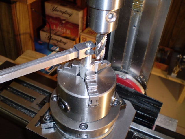
The fig. shows a stop. The movable part clamps to the top of the rotary table’s table. Two of these are needed. The fixed part has been fitted to the hole normally used for the locking mechanism as shown in the previous fig.
It will be noticed that the same hole on the rotary table is used for both locking and for a stop. But, of course, in practice, it will, at any one time, only be needed for one function or the other.
For milling any particular workpiece on a rotary table one has to allow for the space around the workpiece for the clamps used to hold it. For example a 200mm rotary table might hold a workpiece that had to have 120mm hole cut into it. It will be shown later how to effectively extend the diameter of a rotary table. It is often desirable to get the largest rotary table that will fit the milling machine table. However larger rotary tables can be very heavy.
With a large milling machine the practical limit is probably the largest you can lift safely. It is possible to have some sort of lifting gear but this all takes time. It is worth looking carefully before buying because for a given diameter, different makes or different methods of construction can cause a rotary table to vary dramatically in weight.
There will usually be enough space between to milling table and the cutting tool to fit a rotary table to do any required job. But there is always the height of the workpiece to consider. If other devices are to be mounted on the rotary table then the space rapidly disappears.
Most rotary table are set up as shown above to be rotated by a certain number of degrees. This is done using the calibrations on the table marked in degrees.
If it is necessary, when using a rotary table to divide a circle into a number of equal sectors then it is necessary to divide 360º by the number of sectors required. On a small rotary table, the table might only be calibrated to 5°. On larger ones they might be calibrated to individual degrees round the edge but will have a vernier arrangement on the handle so they can be set to a certain number of minutes. This gives us the angle between the sectors. Each time we move from one sector to the next we have to add the angle per sector onto the last angle. For any but the simplest numbers, the chances of getting this right are not great.
It is possible to have dividing plates fitted to a rotating table, as shown above, but this is unusual. But since dividing plates are always fitted to dividing heads these will be covered under dividing heads.
It is quite common to need to be able to divide a circle into so many parts. With dividing plates this is easy and is covered elsewhere. for a rotary table using just degrees and minutes a circle can be divided by one of the following methods.
A calculate the angle in your head or using a calculator for the origin for each sector and write them down. Most simple calculators will give decimal angles whereas the rotary table is marked in degrees and minutes.
B use a spreadsheet to produce a list of angles. These will probably be decimal angles. But is then quite easy to turn decimal degrees into degrees and minutes.
C Use tables showing the angles for each position for a circle divided up to 200 sectors can be found in Appendix C. These are in degrees and minutes.
D use the table for the first 200 sectors that can be found in “Tables for [the] Cooke Optical Dividing Head” published by Cooke, Troughton and Simms.

The maximum capacity of the turntable is not easily specified as it very much depends on how the turntable is used. If you apply a load axially the capacity is very high - in fact it is possible to stand on the rotary table and have it spin you in a circle. If however you have a large over-hanging load that creates a lever arm the capacity is significantly less. The maximum recommended load for the pan/tilt bracket is about 5kg. This can be significantly increased if the load is attached to the side of the turntable instead of over the top.

A rotary table is a mechanical device on a drilling rig that provides clockwise (as viewed from above) rotational force to the drill string to facilitate the process of drilling a borehole. Rotary speed is the number of times the rotary table makes one full revolution in one minute (rpm).
Quote from video: I"m gonna use the spindle with a dial indicator to Center it up once I"m on center I"m gonna clamp down and then. I can offset the milling machines table by the proper.
A rotary engine is an internal combustion engine that separates an engine’s four jobs — intake, compression, combustion, and exhaust — into four individual parts within the overall engine housing. The rotor moves from chamber to chamber, expanding and contracting gas.
There are two groups of big rotary drilling: (1) rotary crushing by high-point loading to the rock from three cones, as shown in Fig. 7.7a, and (2) rotary cutting by shear force from drag bits, as shown in Fig.
A conventional rotary rig or rotary table rig or kelly drive rig is a drilling rig where the rotation of the drill string and bit is applied from a rotary table on the rig floor.
A rotary table is a disc-shaped metalworking device used to obtain precise workpiece positioning. It enables a metalworker to cut or drill a workpiece at precise intervals around a vertically or horizontally fixed axis.
Quote from video: That"s how it"s much better so just install it in a collet. Okay then run run your tool down until it goes into the bore of the rotary. Table. All the way down until it starts to Snug.
A rotary steerable system (RSS) is a form of drilling technology used in directional drilling. It employs the use of specialized downhole equipment to replace conventional directional tools such as mud motors.
A rotary joint, also referred to as a rotary union or rotating union, is a rotary sealing device that connects rotating equipment to fixed piping for the transfer of steam, water, thermal oil, coolant, hydraulic oil, air, and other media.
BALL DRIVE TABLE. Unlike the worm drive, these tables have zero backlash and maintenance, higher speed indexing, higher accuracy, and higher rigidity. …
A rotary indexing table is specifically designed to make repetitive moves around a platform. Essentially, they are highly precise work-positioning devices that index parts to be worked or machined in multiple operations.
With the face horizontal, it has been used to mill curved slots, and could be used equally well to put a radius on the end of a workpiece. If you want to choose between one or the other, the rotary table can be set at any angle, but a dividing head cannot.
A milling table is a part of a standard milling machine. The table is an important part of the machine’s function and is featured on every complete milling machine. The milling table is where a worker sets his work piece in order to mill it with the attached milling head.
Indexing is an operation of dividing a periphery of a cylindrical workpiece into equal number of divisions by the help of index crank and index plate. A manual indexing head includes a hand crank. Rotating the hand crank in turn rotates the spindle and therefore the workpiece.
The workpiece is held on a worktable of the machine. The table movement controls the feed of the workpiece against the rotating cutter. This cutter is fixed on a spindle or arbor which revolves at desired speed.
There are five roll systems in a flour mill: break, sizing, midds (for middlings), low grade, and residue. In the break system, the kernel is opened, the bran flattened and the endosperm broken into large chunks.

A rotary table used in conjunction with a mill allows a machinist to produce virtually any part they can design. Sherline’s rotary table is a precision piece of equipment that has been designed to work with their vertical milling machines, however, it can be used on any mill whenever the small 4-inch size would be an advantage. The only limits are size, not complexity.
The table is 2″ high and 4″ (100mm) in diameter. The main components have been machined from solid bar stock steel, and the complete unit weighs seven pounds. The table has been engraved with a laser, giving sharp and precise lines every 5°, numbered every 15°. These lines are calibrated with the 72-tooth worm gear that is driven by the handwheel. The handwheel is divided into 50 parts, making each line on the handwheel 1/10°. This allows a circle to be divided into 3600 increments without interpolation. Seventy-two revolutions of the handwheel rotate the table one revolution.
The rotary tables can hold more weight when they are not under a continuous load. Click on the Video tab above to see examples of different weights and uses for our rotary tables.
The table T-slots are identical to those used on the Sherline mill and lathe, making the vast line of Sherline tooling available for use with this product. Two hold-down clamps and T-nuts are provided with the table. Also included is an adapter that allows Sherline’s 3- and 4-jaw chucks to be screwed directly to the rotary table. An optional right-angle attachment is available (P/N 3701) to mount the table in the vertical position to further increase its versatility. With the table mounted vertically, an optional adjustable right-angle tailstock (P/N 3702) can be mounted to the mill table. It is used to support and stabilize the other end of long work held in a chuck or otherwise attached to the rotary table.


 8613371530291