
how to build a rotary table factory

For a corner fillet weld such as those, it may help if you grind off half of each corner on the slotted plates giving a 45 deg V. This will help to ensure the weld gets good penetration and strength at the same time as allowing you to retain the original edges for alignment.
Looks to me like you are using a 240V single phase welder. In Oz I would use a Satin craft 13 electrode as these have a slower flux than a Satin craft 12. This helps stop the flux from running into the weld pool and stopping the arc. My welder has only 2 settings 2.5 and 3.2 mm so I try and use the shortest possible cable between the power point and the welder. If I have to go longer a heavier duty cable helps keep up the volts and amps.
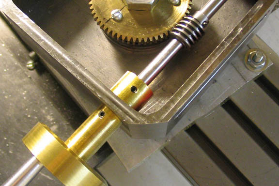
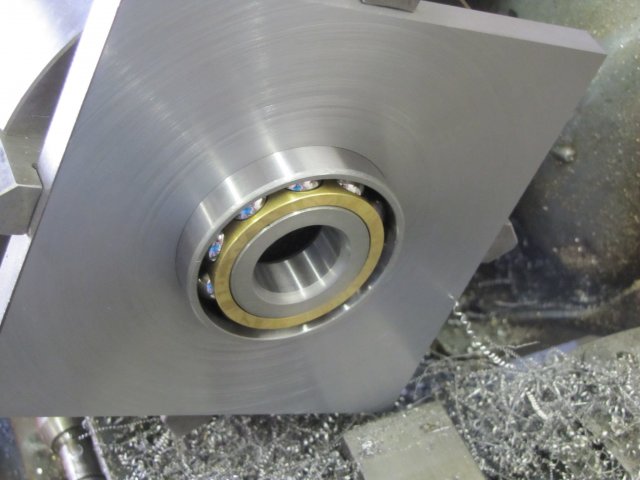
I was once thinking 2 standard transmission flywheels would make a fixture that you are needing. the bottom fly wheel would be surface side down with no ring gear for a bolt down flange. The top flywheel would be face up with a seriese of tapped hole for hold down capabilitys. Im still pondering on the bearing between the 2. The ring gear on the upper flywheel can be mated with a crank handle to provide rotation.

When autocomplete results are available use up and down arrows to review and enter to select. Touch device users, explore by touch or with swipe gestures.
This website or its third-party tools process personal data (e.g. browsing data or IP addresses) and use cookies or other identifiers, which are necessary for its functioning and required to achieve the purposes illustrated in the cookie policy. To learn more, please refer to the cookie policy. In case of sale of your personal information, you may opt out by sending us an email via our Contact Us page. To find out more about the categories of personal information collected and the purposes for which such information will be used, please refer to our privacy policy. You accept the use of cookies or other identifiers by closing or dismissing this notice, by scrolling this page, by clicking a link or button or by continuing to browse otherwise.

This website or its third-party tools process personal data (e.g. browsing data or IP addresses) and use cookies or other identifiers, which are necessary for its functioning and required to achieve the purposes illustrated in the cookie policy. To learn more, please refer to the cookie policy. In case of sale of your personal information, you may opt out by sending us an email via our Contact Us page. To find out more about the categories of personal information collected and the purposes for which such information will be used, please refer to our privacy policy. You accept the use of cookies or other identifiers by closing or dismissing this notice, by scrolling this page, by clicking a link or button or by continuing to browse otherwise.
At Rusach International,rotary table design, engineering and manufacturing & pallet system design, engineering and manufacturing is our specialty. We can supply rotary tables from 100mm up to 8 Meters in diameter. See our rotary table pages. We specialize in high accuracy, up to +/- 1 arc second, heavy load capacity, large work pieces, production style, heavy duty rotary tables and pallet shuttle/storage/transfer systems. We also have a line of standard small production tables that are very cost effective, yet can be customized per application.
Rusach International systems are not proprietary and therefore can be integrated into any machine, control system or application. We do not believe in “locking” a customer down with proprietary parts! We work with all the major industry control, motor and encoder manufacturers.
As CNC machine tool technology has evolved it’s possible to do more operations better, faster and at lower cost than ever before. These advances also mean that there are more machine components and accessories to monitor and maintain. Often overlooked are rotary or trunnion tables that reduce setup and cycle times and, in many applications, enable the machining of complex parts.
Properly functioning rotaries and trunnions are essential to making accurate parts, and like other critical machine components should be checked regularly for signs of wear or damage. The most obvious tipoff that something is wrong with the rotary device is that you experience difficulty setting up a part, or begin producing out-of-tolerance parts. However there are 3 simple checks that, if done regularly, can help keep your rotary tables and trunnions in peak working order:
Check the oil sight glass for discolored or cloudy conditions. This may indicate that a seal has failed and coolant, dirt or other debris is in the lubrication system. Contaminated oil cannot properly protect the inner workings of the rotary device and can cause thousands of dollars in damage.
Inspect cables to make sure they aren’t broken or becoming soft and worn. A short in the electrical circuits caused by faulty cables can seriously damage electrical components.
Keep the control unit clean and free of moisture, oil and dirt. All electronic controls are subject to failure if the circuit boards are compromised. This is especially true in hot, humid conditions or when there is substantial oil residue in the air.
If you find that your Haas made rotary devices need maintenance or repair, contact your Torrance, CA Haas Factory Outlet for quick and reliable service. Since 1986 Haas has built and sold over 55,000 rotaries and trunnions for Haas and other machine tools, and provides comprehensive service on all 35 models.
Most jobs are turned around in 7 to 10 business days and include a thorough inspection to determine what components need attention to bring the rotary device back to factory specifications. This process includes:
Your Torrance, CA HFO technical service professionals will be happy to discuss your specific rotary device needs and can provide rentals or loaners to help minimize the impact on your production schedules. Learn more by calling Gabriel Monroy, 310-381-0750 Ext. 17526. Or email: gmonroy@haasfactoryoutlet.com. Visit www.haasfactoryoutlet.com for all the local Haas news.
Indexing tables are used in a multitude of industries and in numerous applications. Their design is optimal for many manufacturing jobs, and they are a critical component in most automated manufacturing systems. Indexing tables are best defined as a machine tool positioning device. They carry components in a manufacturing environment with a repeating process of indexing (rotating) around an axis, stopping, dwelling while an operation is performed, then indexing again to repeat the process. They are usually made of circular steel plates, with one or more spindles, a drive system, encoders, sensors, controllers and slots or mounting holes to hold components.
Virtually any manufacturing operation can be performed on a part held by an indexing table including welding, grinding, drilling, assembly, painting, inspection, testing and more. In order to maximize operational efficiency, the machine doing the operation must also be built for the same intended application as the indexing table for them to work in synch. Similarly the machine that loads the indexing table with parts must also be synchronized. They must have the same capacity and be able to manage to the same dwell time for the system to work.
If the timing of these machines are coordinated, the time to operate on or assemble a product can be a fraction of that of workers assembling a product.
Industries that use indexing tables include automotive manufacturers, bottling companies, microchip manufacturers, pharmaceutical makers, consumer products companies and many more. They are invaluable to manufacturers pushing for automation and increased efficiency in their factories, turning work that used to take days into work that takes only hours. If a simple assembly task is required on small parts in a factory, there is no better way to complete the task than by coupling an assembly tool and an indexing table.

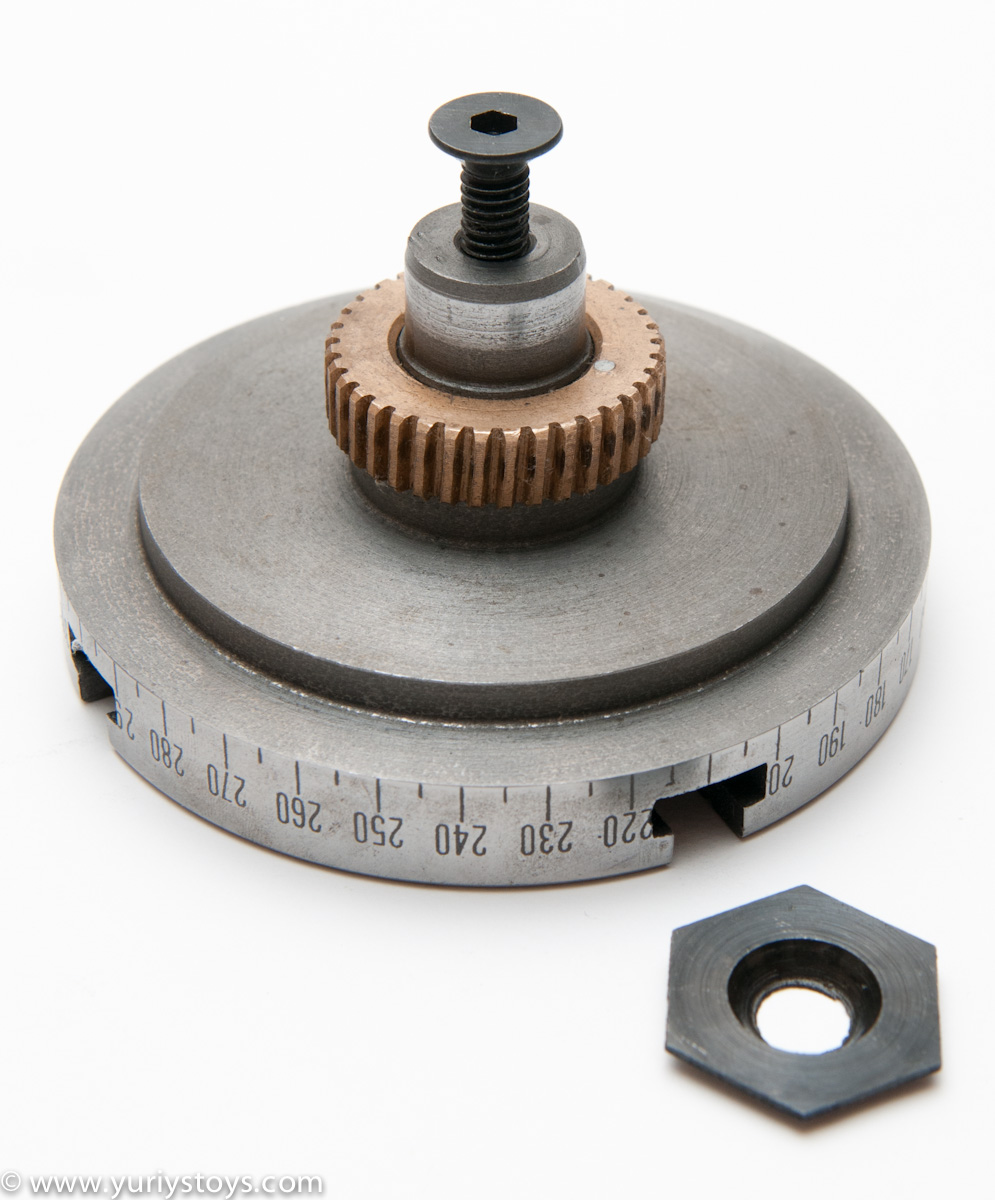
Drill holes and bolt-hole patterns, mill intersecting slots and curved slots precisely. Includes worm drive hand wheel with Vernier ring for 4-degree table movement per turn, three T-slot ways for easily mounting a chuck, and two table clamp handles for stability. Main body mounts horizontally and vertically. You will need the table, tailstock, and chuck to complete your rotary table. The 6” table is a complete pack including the dividing plates and the tailstock. The 8” table takes 1/2” T-slot nuts (35-110) and has an MT3 bore. The 6" table uses 10 mm t-slot nuts and has an MT2 bore.

-Select-AfghanistanAlbaniaAlgeriaAmerican SamoaAndorraAngolaAnguillaAntigua and BarbudaArgentinaArmeniaArubaAustraliaAustriaAzerbaijan RepublicBahamasBahrainBangladeshBelarusBelgiumBelizeBeninBermudaBhutanBoliviaBosnia and HerzegovinaBotswanaBrazilBritish Virgin IslandsBrunei DarussalamBulgariaBurkina FasoBurundiCambodiaCameroonCanadaCape Verde IslandsCayman IslandsCentral African RepublicChadChileChinaColombiaComorosCook IslandsCosta RicaCyprusCzech RepublicCôte d"Ivoire (Ivory Coast)Democratic Republic of the CongoDenmarkDjiboutiDominicaDominican RepublicEcuadorEgyptEl SalvadorEquatorial GuineaEritreaEstoniaEthiopiaFalkland Islands (Islas Malvinas)FijiFinlandFranceGabon RepublicGambiaGeorgiaGermanyGhanaGibraltarGreeceGreenlandGrenadaGuamGuatemalaGuernseyGuineaGuinea-BissauGuyanaHaitiHondurasHong KongHungaryIcelandIndiaIndonesiaIraqIrelandIsraelItalyJamaicaJapanJerseyJordanKazakhstanKenyaKiribatiKuwaitKyrgyzstanLaosLatviaLebanonLesothoLiberiaLiechtensteinLithuaniaLuxembourgMacauMacedoniaMadagascarMalawiMalaysiaMaldivesMaliMaltaMarshall IslandsMauritaniaMauritiusMayotteMexicoMicronesiaMoldovaMonacoMongoliaMontenegroMontserratMoroccoMozambiqueNamibiaNauruNepalNetherlandsNetherlands AntillesNew ZealandNicaraguaNigerNigeriaNiueNorwayOmanPakistanPalauPanamaPapua New GuineaParaguayPeruPhilippinesPolandPortugalPuerto RicoQatarRepublic of CroatiaRepublic of the CongoRomaniaRwandaSaint HelenaSaint Kitts-NevisSaint LuciaSaint Pierre and MiquelonSaint Vincent and the GrenadinesSan MarinoSaudi ArabiaSenegalSerbiaSeychellesSierra LeoneSingaporeSlovakiaSloveniaSolomon IslandsSomaliaSouth AfricaSouth KoreaSpainSri LankaSurinameSwazilandSwedenSwitzerlandTaiwanTajikistanTanzaniaThailandTogoTongaTrinidad and TobagoTunisiaTurkeyTurkmenistanTurks and Caicos IslandsTuvaluUgandaUnited Arab EmiratesUnited KingdomUnited StatesUruguayUzbekistanVanuatuVatican City StateVietnamVirgin Islands (U.S.)Wallis and FutunaWestern SaharaWestern SamoaYemenZambiaZimbabwe
Rotary indexing table use is widespread in automated assembly machinery and selecting the proper mechanism is essential for both maximizing performance and minimizing the cost of this critical component. This how-to-guide will explore two common devices that can be used for rotary indexing and give advice for proper selection. These two popular devices are cam indexing drives and servo rotary tables.
Cam indexers are a ubiquitous mechanism that have been used for rotary tables for many decades. They are a great fit for applications that will always index the same angle and that require high-precision positioning at a very reasonable cost. A cam indexer uses a mechanical cam to provide the motion control to position the load. A mathematical motion curve is machined onto the cam that provides extremely smooth and repeatable motion.
A cam indexer has two main modes of operation. One mode is referred to as “Cycle-on-Demand”. This indicates that the camshaft will be cycled one revolution at a time to advance the output one position at a time. This is typically achieved by using an inexpensive camshaft sensor package to detect camshaft position and a VFD to stop and start the motor. The camshaft dwell period offers a wide window for the camshaft to stop without affecting the position of the output. To cycle the indexer, a PLC gives a command to the VFD to accelerate the drive motor to a preset speed, the cam rotates one revolution indexing the output, a sensor sends an in-position signal to the PLC, and the PLC signals the VFD to stop the camshaft during the cam dwell position. The table will be in the dwell position for however long is necessary to complete the work at each station. The dwell time can range from a fraction of a second to several minutes or hours depending on the application. This combination allows very accurate positioning with an inexpensive drive system.
A cam indexer can also be run in a more traditional “Continuous” mode where the camshaft spins at a constant speed and the indexing and dwell time is controlled solely by the cam motion profile. Continuous mode is useful when other equipment will be mechanically synchronized with the camshaft timing or when the indexer needs to run at cycle rates faster than a motor can be stopped and started. A continuous indexer can run at rates in excess of 1,000 cpm. The limitation of continuous mode is that it may be impossible to machine a cam that requires a quick indexing motion followed by a long dwell time.
A fully programmable servo rotary table is another common option. There are two specific cases where a servo rotary table is advantageous. The first is when a flexible motion pattern is required. An example is two different products being run on one machine that each require different indexing patterns. The other situation that suits a servo indexer is when extremely fast positioning is required followed by a long dwell period. A cycle-on-demand cam indexer is limited by the need to accelerate the camshaft up to speed during the dwell period before output motion is started. There are practical limitations to how fast the camshaft can be accelerated so there will be a delay before motion is started. With a servo rotary table, the output rotates as soon as the servomotor starts moving. A practical example would be a load being indexed 90 degrees in 0.25 seconds. This is not difficult for a continuous cam indexer or a zero-backlash servo indexer, but a cycle-on-demand cam indexer may struggle with that motion. For quick servo indexing applications, a preloaded gear reducer with zero-backlash is critical to achieving smooth indexing motions with minimal settling time. A zero-backlash RollerDrive mechanism would be an optimal choice to achieve accurate positioning with great dynamic response.
For either style of indexer, application information including moment of inertia, indexing angle, indexing time, and dwell time is required. A reputable manufacture should then be able to properly size the rotary table for the application.


 8613371530291