
how to make a rotary table free sample

This website is using a security service to protect itself from online attacks. The action you just performed triggered the security solution. There are several actions that could trigger this block including submitting a certain word or phrase, a SQL command or malformed data.

If the charts for your table are anything like the ones going the rounds for "Other Makes" being sold,you might be as well off without them and try pot luck,or buy a Lotto Ticket.. The errors in these charts have to be seen to be believed.
When you say a chart, what do you want it to tell you, especially as it doesn"t have any plates? Obviously one turn is 4 degrees, and one division a tenth of a degree. As it has a 90 tooth wheel, any tables for a 90 tooth wheel will apply such as those for the Myford DH, of which I have a copy somewhere. That would help you if you had the plates. But actually it"s easy to work out without the tables.
I had no charts with my rotary table (good price, second hand, a long time ago). I have no wish of any charts, especially after reading of the errors here and elsewhere.
After some calculations, and with the help of the Chart, you could start making up your own Division Plates, if you can"t find any for sale anywhere. With each new plate, you should be able to make the others that you might need. In any case it would be useful experience.
I do, and have, (probably more than any other use) almost from when I first bought it. (DP20, Mod 1, Mod 1.25, Mod 1.5 so far), as well as graduating plates, and milling radii.
It was cutting a 13T gear that highlighted the errors in the Vertex HV6 chart. And, if i was to repair my smash up, I HAD to find a way of correcting things!
Someone gave the very useful tip to make up a peg, to act as a stop, and reference point for the fingers, (obviously move it around as the fingers are repositioned).
I do, and have, (probably more than any other use) almost from when I first bought it. (DP20, Mod 1, Mod 1.25, Mod 1.5 so far), as well as graduating plates, and milling radii.
But if the charts are inaccurate they are useless for spacing holes, gear teeth or anything else. As I found out to my cost. It wasted three days of my time, and material to discover that it was not my counting at fault, but the ****** chart supplied with the RT. (* errors or omissions) A day or more on the PC with EXCEL resulted in a spreadsheet and chart which appears to be accurate.
Possibly, amending the Ratio formula in the spreadsheet, would enable a chart to be produced for Rotary tables / Dividing Heads with different ratios, such as 40:1 which seems to be a popular one.
Possibly, amending the Ratio formula in the spreadsheet, would enable a chart to be produced for Rotary tables / Dividing Heads with different ratios, such as 40:1 which seems to be a popular one.
Yes indeed,I was refering to the charts,sorry if I caused any misunderstanding. The tables sometimes have their own problems ! How do I know ? Dont even ask !
Have just spent the last couple of hours copying the table of possible divisions with a 90:1 ratio device, onto my PC from Harold Hall"s book on Dividing, Workshop Practice Series No 37. (Might come in handy one day)
To my immense joy, it does not call for any other than the three plates that I already have, and covers from Divisions 20 to 360, but obviously there are gaps.
No doubt with extra plates, some, if not all, of the gaps could be filled, if required. Maybe, one day, I"ll get round to making another couple of plates, to fill more of the gaps, but don"t hold your breath!
Possibly some of the errors found result from misreading poorly handwritten written characters. Whatever the cause, the errors cause a lot of folk a lot of anger, frustration and waste. Not to mention time spent making calculations to correct the errors!
If you want to know the number of holes on the plates supplied with the HV6, (which is also 90:1) please PM me, and i will supply the details for each of the three plates, (and the extra two that MAY, one day, be made to supplement) They can be made in an enlarged form to fit your Excel, and you will then be in business.
How would I mount the plates? It did not come with any and I have never heard of this being mentioned before this. I thought the ones that had plates were made that way. You Guys make figuring this stuff out look really easy, sort of like watching a welding video.
The combination of a 90 gear and 48 graduations on the dial will give you a wide choice of divisions [excepting those that involve the awkward prime numbers like 7, 11, 13, etc.]
Eurika, I see says the blind man. I did the maths and was getting 4 graduations on the dial was .333. Getting 4 divisions to a degree makes every graduation worth 1/4 degree,makes sense now.
On the HV6-type RT removing the winding handle reveals 3 screw holes that hold the plate mechanism. The mechanics are quite simple - you add a sort of clock pointer to the existing handle that allows you to index a peg into holes drilled in a dividing plate. All it does is help you keep count when keeping count isn"t bleeding obvious. Like cutting a gear with say, 27 teeth, you have to repeatedly do things like "turn the handle completely 4 times and then go past 7 extra index holes" to get the right angle. The tables tell you which plate and set of holes are needed to achieve a given tooth count; the clock pointer follows the position of the extra indexing so you don"t forget where the new start point is.
Easier to do than describe but I make mistakes galore. Instead I built a stepper-motor controlled by an Arduino to do the maths and the winding. It"s just as easy to set up, you don"t need any tables or thinking, and it never gets bored and loses the plot like I do.
PS Speaking of losing the plot, I typed this post while waiting for my meal to cook. Just discovered I forgot to put it in the oven. Back to square one...
The Computer-Aided Design ("CAD") files and all associated content posted to this website are created, uploaded, managed and owned by third-party users. Each CAD and any associated text, image or data is in no way sponsored by or affiliated with any company, organization or real-world item, product, or good it may purport to portray.
Years ago, before I learned CNC, I owned a Phase II 8″ horizontal/vertical rotary table that I purchased from Kap Pullen’s Getmachinetools.com store. He has them at a good price, BTW, and he’s a darned nice fellow to deal with as well as being a frequent HSM contributor. Anyway, its a nice little table, but I hadn’t done a whole lot with it for quite a while after purchasing it. As is so often the case, one day, a project landed on my doorstep and I was glad to have it.
Before I could get started, however, I had to make some accessories for it. Basically, I needed some T-Nuts to fit the table, as well as a little fixture that makes it easy to hold a plate up off the table through a hole in the center so you can machine it. The latter, what I call a “plate machining fixture”, was inspired by something similar I saw the Widgitmaster of CNCZone fame using to make Dremel clamps for his mini-router:
The Plate Maching Fixture and 3 Homemade T-Nuts. T-Nuts are easy to make: square a block to the proper dimensions, mill the side reliefs, drill, and tap. These are much smaller than the mill’s Bridgeport standard T-slots, so I made them myself and I’m using 1/4-20 bolts with them. They’re made of mild steel.
I turned the round spigot using the 4-jaw on the lathe. I’m making the fixture out of MIC-6 aluminum plate, which is pre-ground very flat on the sides. This is a 5 inch by 3 inch piece. I’ve clamped it to the rotab using my T-nuts and the regular mill clamps and step blocks. It is sitting on parallels to make sure I don’t cut into the table. You can also see how I’ve clamped the rotary table to the mill table using a big cast iron V-block I have. You can never have to many blocks with precision faces hanging around!
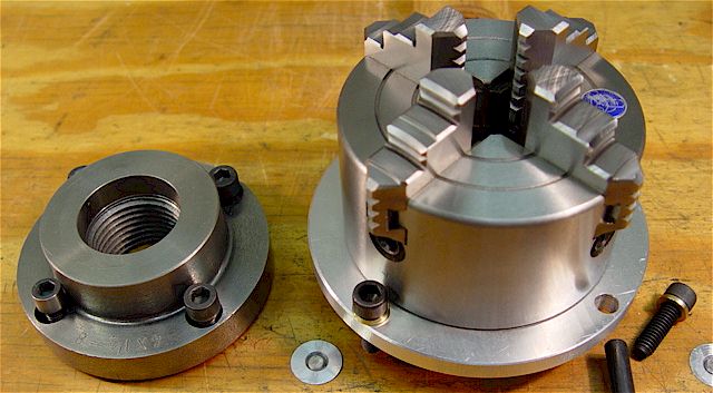
Having a 4-jaw chuck on your rotary table is mighty handy! Because it’s a 4-jaw, you can dial in the workpiece by adjusting the jaws until it is perfectly concentric with the table’s axis of rotation. The best way is to make an adapter plate that attaches to the back of the chuck in the same way that your lathe does so you can exchange lathe tooling with the rotab. Here is an example:
For the example, the chuck is threaded onto the adaptor plate, and then the holes in the adapter plate’s flange are used to bolt down to T-nuts on the table.
In my case, I bought a 4-jaw from Shars brand new, and simply drilled some through-holes in the chuck to mount to the table directly without an adapter plate:
First, you want to make sure your part is properly centered on the table. To do that, I clamp the table down on the mill table (no special place is needed), put my Indicol indicator holder on the mill spindle, and find some round feature on the part to indicate on. For example, on the plate milling fixture above, indicate on the round boss, or on the center hole. Spin the table and bump the part in until spinning the table doesn’t move the indicator.
Second, locate the center of rotation directly under the mill spindle. You can simply use the X and Y table handwheels to do this. Use that Indicol to indicate off of a circular feature you want centered under the spindle. Turn the indicol around on the spindle and adjust the handwheels until the indicator stays put relative to the spindle position. A Blake Coaxial indicator will make this last even simpler.
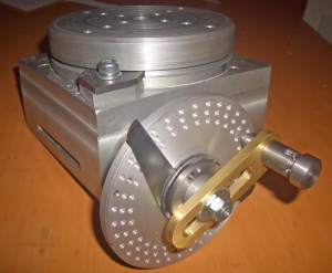
When you’re rounding partially by cranking a part around on the rotary table, it’s really easy to go a little too far and screw things up. The answer is to drill the end points to make the exact stopping point on the rotab a lot less sensitive:
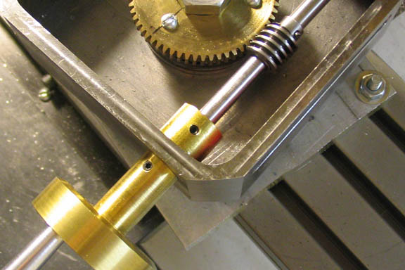
Centering with a Blake indicator is really fast, but what if you don’t have a Blake, or worse, what if your mill is too small to accomodate one? Here is a nice solution I found on a German site. This fellow has made an ER collect fixture for his rotary table, and has taken care that when installed on the table, the axis of the collet is aligned with the table’s axis. He can then place a dowel or other straight pin in the collet and line up until it will go into a similarly sized collet on the spindle. Nice trick! It’s similar to how Widgitmaster showed me to align a drill chuck on a QCTP to the lathe centerline with a dowel pin held in the lathe chuck.
.jpg)
A popular question that we hear is, “How do I size a motor for my application?” This post looks at an example Rotary Index Table application and provides the equations and considerations needed to make the appropriate motor selection.
First, consider your machine’s movement. In our sample case of a Rotary Index Table, an engineer will need to first define all relevant information that will be used later in the Torque calculation. Typical information we will need includes:
The move profile will define the required move distance along with the time for acceleration, constant run, deceleration, and the dwell time between cycles. The velocity move profile can take on a triangular or trapezoidal shape as shown below. For this exercise, we will assume there is no s-curve to smooth the transition points.
The move profile can indicate a linear or rotational movement. The total area under the velocity curve defines the total move distance. Utilizing the data from the move profile will allow us to define the required maximum output speed of the motor.
Since we want to define the required motor torque, we want to be sure that we are using values that pertain directly to the motor itself. If there is a gearbox in the system, we need to be sure to reflect the required values back to the motor. We will need to determine the acceleration torque, deceleration torque, constant torque, and any torque due to gravity on the system. For this exercise, we will assume the index table is in a horizontal position, so the torque due to gravity will be zero.
Using the maximum angular velocity and deceleration times, we can calculate the angular acceleration, αaccel_motorand angular deceleration, αdecel_motor.
Once we know the angular acceleration of the motor, we need to calculate the inertia of the load connected to the motor. In this case, we can approximate the index table inertia using the formula for a solid cylinder.
The load on the index table must also be taken into account. If the load is distributed evenly over the indexed surface, we can add this load into table weight to calculate the inertia of the complete system. If the load is not distributed evenly, then a separate load inertia will need to be determined, Jload.
Now that we know our inertia and our acceleration and deceleration rate, we can determine the required torque. If known, we can add in the inertia of the motor, Jmotor, the gearbox, Jgearbox and a brake on the motor, Jbrake,if the system has a brake.
Depending on the design of the system, there may be a constant friction torque, Mfriction, which must also be accounted for in the motor sizing. The amount of this constant torque will be dependent on the friction coefficient of the system and the weight of the table and load. Again, if there is a speed reduction in the system we can reflect this back to the motor shaft.
We can calculate the required torque for each of the operating sections of the move profile. The acceleration (Figure 2), constant run (Figure 3), and deceleration (Figure 4).
Note that the friction torque helps to slow the system. This can be used to allow the time to decelerate the system to be reduced and the time to accelerate the system increased. This has the advantage of decreasing the peak torque requirement of the motor. If the application allows a faster deceleration time, this may allow the motor size to be reduced.
In addition to determining if the motor has sufficient torque to make the move as defined by the move profile, we must also verify the rms motor torque over the complete cycle is less than or equal to the rated torque of the motor. If the rms torque is higher than the rated torque of the motor, the motor may overheat.
To calculate the rms torque over the cycle, we need to know the dwell time between cycles, tdwell, and the constant run time of the move profile if it is a trapezoidal move.
Optimizing the motor sizing for an indexing application can be an iterative process. By calculating the peak requirements and rms torque of the application, the selection of the motor can be done with confidence to provide a reliable solution for the application (see Figure 7).
In our example, we would want to make a motor selection that offers rated torque above the calculated rms torque value across the needed speed range. Additionally, we would want to make sure the peak torque (red line) is more than the calculated maximum torque value.
Do you have questions about choosing the correct motor size and technology for your application? Contact a KEB Engineer today to discuss your machine design.

I"m attaching a copy of the page of the info sheet that came with the table. I hope it"s not too long for the forum. I called Enco late today and they are going to call Pahse II in the morning and get us all together in a conference call, to see if we can work this out. I have uploaded some close up pictures of the table so that those that do not know exactly what we are talking about can see and maybe better understand. The breakdown of the handles sucks, but it is the only thing supplied.
1. Always rotate hand wheel (Ref. No.46) clockwise. This will eliminate any backlash in the worm gear. If handwheel is rotated past desired position, rotate handwheel one full turn counterclockwise and the rotate handwheel clockwise to desired position.
2. The worm shaft (Ref. No.31) can be disengaged from the table (Ref. No 2) so that operator can rotate table by hand. Loosen handle (Ref. No. 25) by turning it counterclockwise, loosen handle (Ref. No 39) and turn vernier collar (Ref. No 40) clockwise until it is snug. Table can now be rotated by hand. To engage
3. Table is locked into position by rotating clamp handles ( Ref.No. 7) clockwise until snug. Turn handles counterclockwise to free table. Turning the handle (Ref. No. 47) after loosening handle (Ref. No. 39) rotates the table.
4; The table is provided with a scale to indicate the angle of rotation. The indicator (Ref.No. 22) can be used to verify the angle of rotation on scale. The indicator can be adjusted by loosening the knob (Ref. No.23) and moving the indicator along the slot. Secure knob after completing adjustment.
5. The center sleeve has been ground to a Morse Taper. Centers with a Morse Taper shank can be mounted to the rotary table for precision centering and measuring operations. (see dimensions in Fig. 1 for MT of ea. table.)
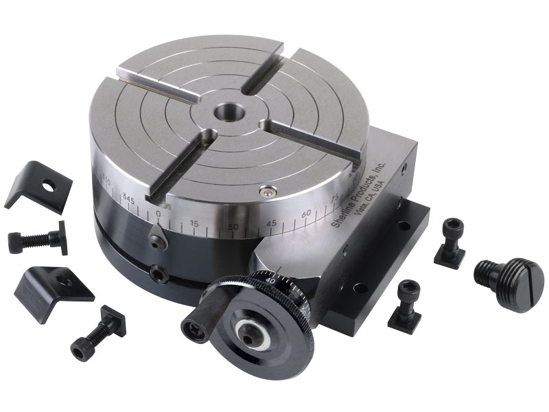
6. The gear ratio of the rotary table is 1: 90 so that 90 rotations of the hand wheel rotate exactly one full rotation. One rotation of the handwheel is equal to 4° rotation of the table. The micro collar is graduated into one minute increments.
The dividing plate accessory ( 241-101) is used to divide one 3600 table rotation into 2-66 and all divisible by 2, 3, and 5 from 67-132 equal divisions, The gear ratio of the rotary table is 1 :90 so 90 rotations of the
handwheel rotate table one full rotation. Therefore for one full rotation of the table, the number of handwheel rotations per divisions "N" times the number of divisions "T" is equal to 90 rotations of the handwheel. So N x
T= 90 or N = 90 ..:.. T. The dividing chart ( page 4) was developed using this relationship, For example if 17 divisions are required, then T=17, so N= 9°/17 =55/17 = 5 1°/34"
To obtain 17 divisions the handwheel is rotated 5 full rotations and 10 holes on the 34 hole circle for each division. The sector is used to make the 10 hole rotation quick and easy.
This website or its third-party tools process personal data (e.g. browsing data or IP addresses) and use cookies or other identifiers, which are necessary for its functioning and required to achieve the purposes illustrated in the cookie policy. To learn more, please refer to the cookie policy. In case of sale of your personal information, you may opt out by sending us an email via our Contact Us page. To find out more about the categories of personal information collected and the purposes for which such information will be used, please refer to our privacy policy. You accept the use of cookies or other identifiers by closing or dismissing this notice, by scrolling this page, by clicking a link or button or by continuing to browse otherwise.
In 1996, Precision Detroit Company established a relationship with WEISS GmbH. WEISS has been manufacturing high quality index tables for decades and is the leading automation component manufacturer in Europe today.
In August, 2007, WEISS GmbH established WEISS North America, Inc. as a wholly-owned subsidiary. On September 30, 2007, WEISS North America, Inc. acquired the assets of Precision Detroit Company, Inc. relative to its PDC Geneva Motion index tables and its network of sales representatives throughout the U.S. and Canada.
Today, WEISS North America is not only a rotary table manufacturer but your complete automation manufacturer and solutions partner. WEISS has decades of expertise in providing automation, drive and control solutions to industrial markets. WEISS offers industry-specific, cost-effective and efficient technology solutions to help you maximize your efficiency, increase your productivity and achieve optimal system performance. We understand that your application has unique processes and specific requirements and we work closely with you to develop the perfect automation solution for your particular needs.
Successfully competing in our increasingly competitive global environment requires strategy, innovation and proven reliability from a partner that you can trust. Give us a call at 888-WEISSNA, fill out the form above, schedule a call below or simply send us an email to discuss your automation needs.

M-035 series high precision rotary tables rotation stages feature high resolution, excellent repeatability and minimum wobble. These high performance rotational positioning stages are equipped with double ball bearings for minimum backlash and high load capacity. Both the rotation stage platform and the scale ring (graduated in 2-degree increments) can be independently coarse positioned over 360 degrees and then be locked by screws.
The basic rotary table version, M-035.D0, is equipped with a DC servo motor drive providing a positioning range of ± 6.3 degrees. A set of limit switches eliminates the possibility of overtravel. For the highest precision and highest performance, high speed air bearing rotary tables are recommended.
The versions M-035.DS and M-035.DP provide additional piezoelectric fine adjustment over a range of ±520 µrad. The piezoelectric fine adjustment also allows dynamic operation such as scanning or tracking. The .DS version is equipped with a closed loop PZT drive (model P-841.30), while the .DP version comes with an open loop PZT drive (model P-840.30). Both drives provide a linear range of 45 microns and sub-nanometer linear resolution (see "PZT Actuators" section for further details and recommended drivers).

If you ended up on this page doing normal allowed operations, please contact our support at support@mdpi.com. Please include what you were doing when this page came up and the Ray ID & Your IP found at the


 8613371530291