
how to use a rotary table on a milling machine free sample

Years ago, before I learned CNC, I owned a Phase II 8″ horizontal/vertical rotary table that I purchased from Kap Pullen’s Getmachinetools.com store. He has them at a good price, BTW, and he’s a darned nice fellow to deal with as well as being a frequent HSM contributor. Anyway, its a nice little table, but I hadn’t done a whole lot with it for quite a while after purchasing it. As is so often the case, one day, a project landed on my doorstep and I was glad to have it.
Before I could get started, however, I had to make some accessories for it. Basically, I needed some T-Nuts to fit the table, as well as a little fixture that makes it easy to hold a plate up off the table through a hole in the center so you can machine it. The latter, what I call a “plate machining fixture”, was inspired by something similar I saw the Widgitmaster of CNCZone fame using to make Dremel clamps for his mini-router:
The Plate Maching Fixture and 3 Homemade T-Nuts. T-Nuts are easy to make: square a block to the proper dimensions, mill the side reliefs, drill, and tap. These are much smaller than the mill’s Bridgeport standard T-slots, so I made them myself and I’m using 1/4-20 bolts with them. They’re made of mild steel.
I turned the round spigot using the 4-jaw on the lathe. I’m making the fixture out of MIC-6 aluminum plate, which is pre-ground very flat on the sides. This is a 5 inch by 3 inch piece. I’ve clamped it to the rotab using my T-nuts and the regular mill clamps and step blocks. It is sitting on parallels to make sure I don’t cut into the table. You can also see how I’ve clamped the rotary table to the mill table using a big cast iron V-block I have. You can never have to many blocks with precision faces hanging around!
Having a 4-jaw chuck on your rotary table is mighty handy! Because it’s a 4-jaw, you can dial in the workpiece by adjusting the jaws until it is perfectly concentric with the table’s axis of rotation. The best way is to make an adapter plate that attaches to the back of the chuck in the same way that your lathe does so you can exchange lathe tooling with the rotab. Here is an example:
For the example, the chuck is threaded onto the adaptor plate, and then the holes in the adapter plate’s flange are used to bolt down to T-nuts on the table.
In my case, I bought a 4-jaw from Shars brand new, and simply drilled some through-holes in the chuck to mount to the table directly without an adapter plate:
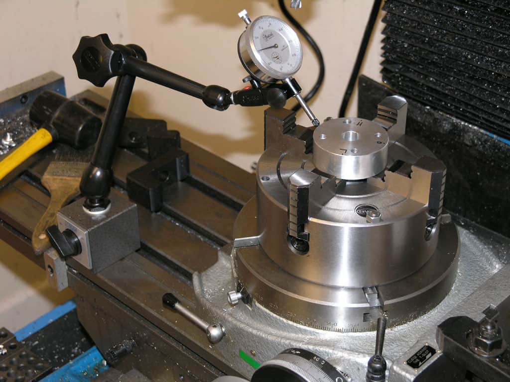
First, you want to make sure your part is properly centered on the table. To do that, I clamp the table down on the mill table (no special place is needed), put my Indicol indicator holder on the mill spindle, and find some round feature on the part to indicate on. For example, on the plate milling fixture above, indicate on the round boss, or on the center hole. Spin the table and bump the part in until spinning the table doesn’t move the indicator.
Second, locate the center of rotation directly under the mill spindle. You can simply use the X and Y table handwheels to do this. Use that Indicol to indicate off of a circular feature you want centered under the spindle. Turn the indicol around on the spindle and adjust the handwheels until the indicator stays put relative to the spindle position. A Blake Coaxial indicator will make this last even simpler.
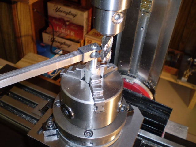
When you’re rounding partially by cranking a part around on the rotary table, it’s really easy to go a little too far and screw things up. The answer is to drill the end points to make the exact stopping point on the rotab a lot less sensitive:
Centering with a Blake indicator is really fast, but what if you don’t have a Blake, or worse, what if your mill is too small to accomodate one? Here is a nice solution I found on a German site. This fellow has made an ER collect fixture for his rotary table, and has taken care that when installed on the table, the axis of the collet is aligned with the table’s axis. He can then place a dowel or other straight pin in the collet and line up until it will go into a similarly sized collet on the spindle. Nice trick! It’s similar to how Widgitmaster showed me to align a drill chuck on a QCTP to the lathe centerline with a dowel pin held in the lathe chuck.
A CNC rotary table is the precision positioning accessory that can provide a reliable 4th axis or even 5th axis for modern machining centers. Utilizing a computer-controlled rotary table can turn the original 3-axis machine tools into 5-axis CNC machines, expanding the accuracy as well as decreasing the costs while performing complex machining operations at one time.
A CNC rotary table is the precision positioning accessory that can provide reliable 4 or even 5 axis cutting operation capabilities for modern machining centers. Utilizing it can turn the original 3-axis machine tools into 5-axis CNC machines, expanding the accuracy as well as decreasing the costs while performing complex machining operations.
Rotary tables typically have rigid frames and coatings, and also excellent torque capacity, which makes the small device flexible and effective for a wide variety of turning, milling, drilling, and more metalworking operations. The easy setup and seamless interface allow the operators to easily add the rotary table to fit their 4-axis or 5-axis applications. .
The working principle is similar to the basic rotary tables, which is to support the workpiece by accurately rotating the workpieces on the axis in order to locate the parts for high precision tooling. Under rapid rotation, which is driven by CNC instructions, the cutting tools of larger machine tools or machining centers can remove the material and add the feature to the products at exact intervals. On rotary tables, there are vertical and horizontal axes for various tools to perform these high-performance metalworks. To enhance the accuracy and flexibility, there are models that employ additional dividing plates and come with additonal material handling mechanisms and features.
Since 4-axis and 5-axis machining is increasingly popular today, adding the CNC rotary table as the 4th axis is an ideal solution to easily open up more complex machining options at a lower cost. Due to the arrangement, they are widely also called the 4th or 5th axis or tilt rotary. The 4th axis, which is the rotational operational direction, is added to the original three linear axes which are known as X-axis, Y-axis, Z-axis. In some cases, there are two rotational axes add to the original 3-axis machining center, achieving utmost accuracy as well as effective multiple face cutting to reach the difficult area on the surface. Rotary tables are usually mounted parallel to the ground or the bed, with the platter rotating around the vertical axis, for example with the most common vertical milling machine combination. Sometimes the machining application requires an alternative setup with the table mountet on its end so that it rotates around the horizontlal axis. Often, a tailstock is used in this configuration. Virtually all models today come with a clamping kit to mount it onto the bed of your machine tool.
The function of the high precision rotary table is also to rotate the workpiece so the cutting tool can create the contour we desired out of the workpiece. However, a rotary table with higher precision has the ability to achieve great accuracy just as its name implies. There is also a major misconception between the resolution and the accuracy.
A common example is that if a digital readout displays to four decimal places, then the high precision rotary table must also be capable of achieving the accuracy to that same value. Even though for higher accuracy to be achieved, the resolution has to also be high, but there is no guarantee that the accuracy is going to be high. The accuracy is the concept which is the difference between the actual position and the position measured by a reference measurement device. The feedback mechanism such as the rotary encoder, and the drive mechanism can influence the accuracy of the advanced rotary table.
A CNC rotary table can provide great rigidity for stable machining operations. It consists of the worktable where the metal parts are held, the rigid bearing that withstands the forces and loads during the rotation, the solid base which is used for attaching the rotary table to the machining center or other equipment, the motor, and the CNC system.
The worktable is the tooling surface where the workpieces are machined after accurate positioning. The worm gearing is the core mechanism of the table, which mesh with the steel worm which is submerged in the lubricants. Both the rigid bearings and the worm gears have large diameters. Excellent concentricity is the key to smooth operation, durability, and most importantly, accuracy. Driven by a computer and electric motor, the worktable can position the materials at exact intervals. For more flexible or critical operations, dividing plates can be added to this component.
A CNC system regulates the simultaneous 4-axis motion of the rotary table. The instructions are programmed and transmitted via CAD software, reducing the time for adjustment and monitoring by human workers.
The type and size of the electric motors utilized in can define the router accuracy as well as the efficiency of the device. Servo motor and stepper motor are two typical types that can be divided into more subtypes. The servo motor uses a closed looping variable circuit, the circuit will constantly run to keep the function. The brushes must be replaced every 2000 hours of operation in the servo motor. Compared to stepper motors, servo motors are more efficient in power consumption. On the other hand, the stepper motor has a simpler setup which are the wires that are attached to the driver. The bearing of the stepper motor is the only wearing component. However, the stepper motor consumes a great amount of energy.
There are currently several different types and models available in the industries. Each of them possess its own traits and abilities. Let us take a look at the most common ones other than standard three axis tables
The 4 axis CNC rotary table will process the workpieces by holding them in the same position while the cutting tool performs along the XYZ plane to trim away the unwanted material. In general, a 4 axis model is very versatile equipment that can be used for several different industrial processes such as engraving curved surfaces, continuous cutting, and intermittent cutting. Besides, people can also add other devices such as cam machining, blade machining, and helical grooves to the 4 axes rotary table. Such a feature is simply impossible to achieve with the machining center which has only 3 axes.
Besides the 4 axis ones, there are also 5 axis models. They have the ability to allow the workpiece to be processed automatically from five sides at one time. people usually utilized the 5 axes rotary table in the industries such as the automobile, the aerospace, and the boating industries. The reason that the 5 axes rotary table is commonly used in heavy industries is that the 5 axis machining is an important technique to be used when the components need better intricacy and quick precision. All of these have more than three axes are called the multi-axis rotary table.
The installation method of the precision rotary table can be horizontal, vertical or inverted. When installed horizontally, the workbench surface is in a flat, vertical and horizontal position. When installed vertically, a rotary table is installed so that the surface of it can run up and down. In the reverse layout, itcan be rotated upside down in a horizontal position. The location of the drive of the rotary table can depend on the mount. The drive can be placed on the back, below, on the top or on the side.
When mounted horizontally, the spinning table top drive is positioned above the table floor. When the rotary table is horizontally placed, the side-mounted drive is located on the edge of the table board. The driving mechanism of the rotary table may be manual, electrical, pneumatic, hydraulic or non-driven. For manual revolving workbenches, release the workbenches and manually spin the workbenches with the crank.
Workpieces are gathered and machined through PC and fully programmed instructions. The 5-axis simultaneous operations will be measurably more reliable than products machined via different technologies. Also, the setup is simple and provides an indistinguishable process in every production cycle, the consistency of the quality of the metal products can be ensured under critical control and precision cutting.
Since the metalwork is driven by software, the preferred frameworks can be programmed and adapted by the rotary table. Saving both the cost and the room makes themis the ideal solution for potential users who don’t want to install larger equipment and new machines which may take up a great room for a wide variety of machining applications.
Another benefit is the utmost movements can be completed precisiely and faster. There are more favorable positions, operation angles as well as accessible machining that can be achieved through the technology. The complex operations are suitable for blade, helical grooves production, and other applications required to add complex features or require critical inspection in machining processes like the manufacturing of aerospace, automotive parts, and scientific equipment.
Addding a rotational table saves time because the extra finishing jobs or other sub-operations can also be performed at one time in the machining center.
A rotary table can be used in many applications including manufacturing, inspection, and assembly. Indicators are used, for example, for assembly, manufacturing, and bottling equipment. They typically use a single item in workspaces or move relatively small layouts of items around stations for sequential work or assembly.
In automated assembly machines, the rotary tables implementation is widespread, and choosing the right mechanism is important for both improving efficiency and reducing the cost of this vital component. This guide discusses two common devices for rotating indexing and offers guidance on the right range. There are several ways to get mass mobilization when it comes to the development of rotary indexing tables. Regardless of whether the load or load in centuries of thousands of kgm2 is incredibly light. When choosing a robust rotary index solution that will match or meet your standards, there are several factors to take into account when spinning, elevating, or pushing.
When determining the influencing factors on the postitioning accuracy, the first thing to look at is the mechanical properties of the table itself. A rotary table contains six degrees of freedom. Each of these movements increases the total risk of positioning errors. Usually, a rotary table is driven by a worm gear, which is connected to the motor through a rotary encoder on the back. The position of the table can be determined by the number of pulses transmitted from the encoder to the control device.
The four main sources of error due to the semi-closed position loop are geometric errors, thermal deformation, elasticity, and wear. The sum of these errors is called angular positioning error. To greatly reduce the angular positioning error, the ideal position for installing the angle encoder is on the rotating shaft under test. The angle encoder is installed under the rotary table, and the rotary encoder is installed under the rear motor, the position loop is now considered a closed-loop system.
Precision is a relative term. About a quarter of an inch is great and will meet the accuracy of its application. Others, for example, require micron-level accuracy in measuring and indexing devices. Then, some applications fall within these extreme ranges.
The misunderstanding is that you may have used an inaccurate indexing device and made it accurate by introducing a pin or wedge locking device. These devices increase the complexity and cycle time of use, and when they are used together with a high-precision positioning device, they may cause damage and reduce accuracy.
In the actual test, by selecting specific components, motion index drive, servo rotary indexer, the measurement accuracy is as high as 5-6 microns. These are not the results approved by Motion Index Drives, but the results of customer certification. When starting and stopping large amounts of data, it is important to know how fast it takes to stop the application with large amounts of data.
In a less rigid environment or the presence of higher recoil, a faster start and stop will bring many control problems. When moving masses (whether rotating mass or linear mass), starting and stopping in a system with a backlash of several arc minutes will cause a lot of back and forth movement in the gear system. The result is a force that is difficult or even impossible to calculate. In addition, when the gear head is used in rotating applications, the farther the mass is from the center of rotation, the greater the backlash. In applications with very slow deceleration times, recoil may not be a problem.
Backlash in the positioning process is a big issue – when it comes to the beginning and stopping volumes, it"s crucial to know how quickly you need to avoid the mass of your rotary indexing table applications. In a less rigid system or where there is an increased backlash, quicker start-ups and stops can cause a lot of control issues. When shifting a mass, whether rotary or linear, starting and stopping in a system with several minutes of backlash arc will create a lot of back-and-forth motion within the gearing system. The effect is a power that can be difficult and probably hard to quantify. In comparison, as the gear head is used for rotational applications, the more the mass is from the axis of rotation, the further the backlash is magnified.
The backlash may not be a concern in systems where deceleration times are incredibly long. In the case of cam indexers, there is " Zero Backlash." The cam indexer and rotary table dynamics give an incredibly rigid, highly regulated framework. A modern cam indexer system is capable of withstanding short cycle times with stop times in milliseconds.
So you want to get the smart manufacturing going but are not sure of what to look for in rotary tables. The information provided in this section may be able to help. The primary factor is to determine the mass snapshot of inactivity. This is often overlooked when measuring a rotary table for the machine.
Another significant factor is the size of the workpiece being rotated, including how big it is and how substantial it is. You want your rotary tables to be large enough to handle enormous pieces. This is where tilling rotary tables may become handy so that the pieces can be handled without causing interior harm. They allow the quickening and decelerating of machining at appropriate rates.
The last factor is accuracy, the applications for which, for instance, pivoting a gigantic part to allow welding highlights on it where the individual stop positions can be genuinely free. On an additional note, when choosing direct drive rotary tables, factors that you should consider when selecting a rotary table for your CNC machinery include accuracy, backlash, mass moment of inertia, acceleration and deceleration, speed, and environment.
Indexing system use is commonly possible in automatic assembly machines and the right process is important for both performance maximization and cost reduction.
Cam indexers are an omnipresent tool used for several decades for rotary indexing tables. They are suitable for applications that often index the same angle and need a high degree of accuracy at a relatively low cost. To place the load, a cam indexer uses a mechanical cam. A math curve is pushed onto the cam and provides incredibly smooth and repeatable movement.
Another popular alternative is a fully programmable rotary index table. A rotary table is advantageous in two different situations. Firstly, a versatile movement pattern is important. An example is if two components are running on one computer, each of which requires different index patterns. For incredibly fast placement accompanied by a long period, another condition that matches the servo pointer is. The need to accelerate the camshaft while the cam indexing mechanism was operating before starting the output movement reduced the on-demand cam indexer. Acceleration of the camshaft is possible, but there is a delay before the movement begins. There are realistic restrictions.
With an indexing table, the output rotates as soon as the servo starts moving. This is not difficult for a continuous cam indexer or a zero-backlash servo indexer, but it can also be difficult for an on-demand cam indexer. For applications with high-speed servo indexing, smooth movements are crucial. A zero-backlash preloaded reducer can achieve this. The ideal alternative for correct positioning with high dynamic response would be the zero-backlash reel drive system.
Application parameters, like a moment of inertia, indexing angle, indexing period, and residence time, are required for each indexer style. The rotary indexing table for the application should also be sized correctly by a reputable manufacturer.

A rotary table used in conjunction with a mill allows a machinist to produce virtually any part they can design. Sherline’s rotary table is a precision piece of equipment that has been designed to work with their vertical milling machines. However, it can be used on any mill whenever the small 4-inch size would be an advantage. The only limits are size, not complexity.
The table is 2″ high and 4″ (100mm) in diameter. The main components have been machined from solid bar stock steel, and the complete unit weighs seven pounds. The table has been engraved with a laser, giving sharp and precise lines every 5°, numbered every 15°. These lines are calibrated with the 72-tooth worm gear that is driven by the handwheel. The handwheel is divided into 50 parts, making each line on the handwheel 1/10°. This allows a circle to be divided into 3600 increments without interpolation. Seventy-two revolutions of the handwheel rotate the table one revolution.
The rotary tables can hold more weight when they are not under a continuous load. Click on the Video tab above to see examples of different weights and uses for our rotary tables.
The table T-slots are identical to those used on the Sherline mill and lathe, making the vast line of Sherline tooling available for use with this product. Two hold-down clamps and T-nuts are provided with the table. Also included is an adapter that allows Sherline’s 3- and 4-jaw chucks to be screwed directly to the rotary table. An optional right-angle attachment is available (P/N 3701) to mount the table in the vertical position to increase its versatility further. With the table mounted vertically, an optional adjustable right-angle tailstock (P/N 3702) can be mounted to the mill table. It is used to support and stabilize the other end of long work held in a chuck or otherwise attached to the rotary table.
A rotary table is a precision work positioning device used in metalworking. It enables the operator to drill or cut work at exact intervals around a fixed (usually horizontal or vertical) axis. Some rotary tables allow the use of index plates for indexing operations, and some can also be fitted with dividing plates that enable regular work positioning at divisions for which indexing plates are not available. A rotary fixture used in this fashion is more appropriately called a dividing head (indexing head).
The table shown is a manually operated type. Powered tables under the control of CNC machines are now available, and provide a fourth axis to CNC milling machines. Rotary tables are made with a solid base, which has provision for clamping onto another table or fixture. The actual table is a precision-machined disc to which the work piece is clamped (T slots are generally provided for this purpose). This disc can rotate freely, for indexing, or under the control of a worm (handwheel), with the worm wheel portion being made part of the actual table. High precision tables are driven by backlash compensating duplex worms.
The ratio between worm and table is generally 40:1, 72:1 or 90:1 but may be any ratio that can be easily divided exactly into 360°. This is for ease of use when indexing plates are available. A graduated dial and, often, a vernier scale enable the operator to position the table, and thus the work affixed to it with great accuracy.
Rotary tables are most commonly mounted "flat", with the table rotating around a vertical axis, in the same plane as the cutter of a vertical milling machine. An alternate setup is to mount the rotary table on its end (or mount it "flat" on a 90° angle plate), so that it rotates about a horizontal axis. In this configuration a tailstock can also be used, thus holding the workpiece "between centers."
With the table mounted on a secondary table, the workpiece is accurately centered on the rotary table"s axis, which in turn is centered on the cutting tool"s axis. All three axes are thus coaxial. From this point, the secondary table can be offset in either the X or Y direction to set the cutter the desired distance from the workpiece"s center. This allows concentric machining operations on the workpiece. Placing the workpiece eccentrically a set distance from the center permits more complex curves to be cut. As with other setups on a vertical mill, the milling operation can be either drilling a series of concentric, and possibly equidistant holes, or face or end milling either circular or semicircular shapes and contours.
To create large-diameter holes, via milling in a circular toolpath, on small milling machines that don"t have the power to drive large twist drills (>0.500"/>13 mm)
with the addition of a compound table on top of the rotary table, the user can move the center of rotation to anywhere on the part being cut. This enables an arc to be cut at any place on the part.
Additionally, if converted to stepper motor operation, with a CNC milling machine and a tailstock, a rotary table allows many parts to be made on a mill that otherwise would require a lathe.
Rotary tables have many applications, including being used in the manufacture and inspection process of important elements in aerospace, automation and scientific industries. The use of rotary tables stretches as far as the film and animation industry, being used to obtain accuracy and precision in filming and photography.

I received a new 4th. Axis from the seller, and this one works fine!...Kudos to the seller for sending me a new one even when I was out of the Amazon’s return window.
After I opened the box and manually tested it I realized that the new one was able to spin without much effort, opposite to the first one I got that it was hard to rotate, but since I didn’t know what to expect I thought it was fine and hard to rotate due to the stepper motor (I didn’t remove it). So here is my recommendation if you get one of these:
Once you receive your package, unscrew and remove the stepper motor (completely), as if you were trying to adjust the belt tension; this shouldn’t void your warranty as you should be able to adjust the belt any time and this is not opening the spindle. Now and without the stepper motor, manually rotate the spindle/chuck; the spindle/chuck should rotate freely, without much effort but not as a skateboard wheel; great if does. Even if you feel a small amount of friction it should be fine as it should be normal on these spindles/chucks. If you have a hard time rotating it (and hear something like a clicking sound) then you should be considering exchange it.
Disappointed!...The spindle it"s barely turning and seemed to got stuck only after a few times using it. this happened right after my Amazon return window expired, so I contacted the seller for diagrams to see if I could open it and do some clean up or add grease, but they do not have any. The seller suggested to "hammer the inside four claws from the front to the back" but that seems radical and I"m not certain it will not damage completely the spindle. I have seen videos of other 4th axis that they have retainers/big nuts that you unscrew to open the interior, but this model has none; not in the back or in the front, and I have not found a site or video that shows how to open any of these models. Do not recommend.
The seller contacted me again and as there are no schematics available, then it"s willing to help me solve the issue in a different way; by sending me a new product for testing and review, and have expedited the shipment. I"ll provide new comments an possible update the overall rating once I have tested and reviewed the new product.

Countless products today, from smartphones to supersonic jets, are made possible because of the reliability and versatility of CNC milling. It’s an ideal method for rapid prototyping, as well as volume manufacturing in plastic and metal. Let’s take a closer look at some of the remarkable advantages and applications for CNC milling.
CNC milling is a manufacturing process that uses a cutting tool mounted on a rotating spindle to selectively remove material from a block of raw substrate. The workpiece is rigidly mounted to a table, and this table moves or rotates on different planes so the tool can work at many angles. Sophisticated CNC milling machines can have 5 or more axes of independent motion to make more complex shapes or to avoid having to move the workpiece to a separate machine.
The axis of motion for a CNC milling machine are based on an X-Y-Z coordinate measuring system. All machinists refer to this when describing the basic movements of the mill, relative to an operator facing the machine. A standard CNC mill for example has three axes. The milling spindle represents the Z-axis, moving up and down. The X-axis is left-to-right, and the Y-axis is front-to-back.
All of these movements of CNC mills rely on Computer Numeric Control, which is a computer program derived from a 3D digital file of the desired finished part.
Early automated machine tools relied on punch cards to control their basic movements in a systematic fashion. This technology worked but it was a slow and cumbersome system and punch cards could not be modified once made. These were later replaced by magnetic tapes, disk drives and now fully digital instructions in G-Code.
This control system is not only fast and accurate but, unlike earlier systems, it can be easily modified as needed, line-by-line and in real time, in order to fine-tune the machining program for the best CNC milling results.
Making a finished part from a block of material requires many different tools, each of them performing a very specific CNC machining function. Changing these tools one at a time by hand would be prohibitively time-consuming and inefficient.
To counter this, CNC milling machines have rotating carousels where all the needed tools are pre-loaded on separate holders. When needed, these CNC milling and machining tools can be exchanged automatically on the spindle within a few seconds.
The carousel on this Haas VF-2SS mill can hold a maximum of 30 tools, plus one on the spindle. This guarantees that all conventional CNC milling operations can be performed in one set-up. We further improve on this efficiency by using an automated tool dispensing system from Guhring. With more than ten thousand cutters in storage we are always assured of having the right CNC machining tool for every milling and CNC turning job.
On a CNC machining center, the workpiece is mounted in a fixed position on a work table while the tool is moved around it. This is the fundamental difference from CNC turning on a lathe, where the workpiece spins while the tool remains stationary.
Because of this fundamental difference in motion, parts are held in place in very different ways on these two machines. In CNC turning, for example, all parts are mounted on a spindle. They are concentric and therefore held securely by a three-jaw chuck right down the centerline of the part, the same way every time. The same is not true for CNC milling, where different holding strategies are needed.
However, other unusual shapes or parts may require custom holding fixtures which can make a CNC machining project more complex and time consuming. We have designed several of our own which were later patented.
Symmetrical parts that are essentially round or radial are best machined on a CNC turning center for maximum efficiency and precision. But most parts we work with are not round or symmetrical so they must be machined on a mill.
Multi-axis mills are unrivalled for creating square shapes, bevels, angles, slots and complex curves – any subtractive machining process can be done on a mill, including making round shapes. They are also accurate, routinely holding tolerances of .01mm or 10 microns. We have a wide variety of stock materials for any application and offer the best incoming material inspection and testing service.
When you upload your CAD files to Star Rapid for a free quotation, not only will you get great parts and prototypes fast, you get peace of mind about the custom manufacturing services we provide.

VEVOR is a leading brand that specializes in equipment and tools. Along with thousands of motivated employees, VEVOR is dedicated to providing our customers with tough equipment & tools at incredibly low prices. Today, VEVOR has occupied markets of more than 200 countries with 10 million plus global members.
VEVOR is a leading brand that specializes in equipment and tools. Along with thousands of motivated employees, VEVOR is dedicated to providing our customers with tough equipment & tools at incredibly low prices. Today, VEVOR has occupied markets of more than 200 countries with 10 million plus global members.
The mill rotary table is one of the main accessories of milling machine. As a precision work positioning device, it is widely used for indexing drilling, milling, circumferential cutting, boring, etc. The rotary turn table for milling machine is made from HT200 casting with high quality. It has already passed the ISO9001 quality system certification. They are are very popular on the market for their superior performance, excellent design and reasonable cost.
Both vertical and horizontal with two functions. Circle cutting, indexing drilling, milling and more complicated work are possible when the vertical position of the table is used together with the tail part.
New: A brand-new, unused, unopened, undamaged item in its original packaging (where packaging is applicable). Packaging should be the same as what is found in a retail store, unless the item was packaged by the manufacturer in non-retail packaging, such as an unprinted box or plastic bag. See the seller"s listing for full details.See all condition definitionsopens in a new window or tab

Adding a 4th axis rotary table to a milling machine provides several advantages to your job shop. Having another axis to work with gives milling machine users more precision and accuracy without having to change part positions.
Also, an additional axis would prove to make any milling machine more diverse in the work it is capable of doing. Lathe machines introduce the aspect of a rotating part, so a rotary table would add the same benefits provided. A 4th axis rotary table, in general, can provide more precision and ease to a complex design, reducing time and costs for the production of a certain piece.
A 4th axis rotary table serves to add a rotating axis to the desired piece being shaped. Similar to a lathe’s rotating head-stock, the rotary table holds the piece and moves it at exact intervals of revolutions.
Because it can move in precise degrees of motion, machinists can easily calculate correct positions, just as they do with the other three axes of motion on the machine. Once all 4 axes are used, making grooves or holes in the piece is much easier than without the rotary table. This saves time by discarding the task of removing and resetting the piece in another position. Having the ability to move the piece in determined intervals and precision in multiple axes is important for more complex machine work.
Just like with the other three axes of motion, the 4th axis can be adjusted for specific amounts of distances to accurately tell what position you are at in relation to the dimensions of the piece.
Also, the scales used to measure its motion can save time and resources by reducing the amount of mistakes that could result in major delays. A 4th axis rotary table can be integrated into a milling machine’s control in order to set the positions needed. This makes accurately machining multiple pieces faster and easier to accomplish.
With a full 4th axis, your milling machine can handle a much more diverse set of jobs. For example, machining parts with holes in which mill must work with a circular pattern with equal distances is certainly possible with 360 degree movements. Arc cuts, grooves, and other complex curves are included with the benefits of a 4th axis rotary table. Cutting out the teeth of gear parts is another possible application.
A 4th axis rotary table extends the degree of motion necessary for complex work needed by any skilled machinist. With quality material, a machinist can create intricate parts and expand the types of orders your job shop can take on.
CNC Indexing & Feeding Technologies offers a wide selection of 4th axis TJR rotary tables. Contact us today to learn about our high quality CNC accessories.

The crosslide table all depends on where the slides are...above the point of rotation or below. Below is pretty much the cheap line and really is redundant putting on a mill as you already have 2 axis there. Now, slides above the pivot point allows you to position your part any where on table, center it above the pivot using the slides (U & V axis?) all with out tapping it about like a rotary table w/o slides. Also, you can then offset a part to center a desired radius elsewhere...example: you need to mill a 4" square hole with r.535 in corners. On a plain rotary table you would need to relocate the part for each corner...with topslides you use the U & V axis to position the center of R.535 over the pivot and turn the corner. This works for all kinds of stuff...milling angles off the X&Y that come tang to a rad, or even milling multiple circles or countours on a single pc w/o remounting and locating the pc. Think of 3 O-ring grooves on a hydraulic cover, or the snowman shape in a gearpump hsg. These can get confusing as now you have a manual machine with C,U,V,W,X,Y,&Z axis....wow.
The best has to be Advance 15X15. I know this unit cost $4500 15 years ago.Troyke made them also but I don"t know of others. Palmgren I thought made the bottom slide type. Alas, the 2axis CNC retros can outrun it and these are rapidly becoming dinosaurs.


 8613371530291