
hv4 rotary table free sample

Kaka Industrial HV-4, 4”Horizontal Vertical Rotary Table Rotary table TSL Vertical & Horizontal MT3 Center Sleeve Rotary Table 3 slot Precision Milling Table 360 Degrees Precision Rotary Table

The crank handle is held in place with a grub screw – ensure this is tight and that the handle and pin are at 90° to the crank plate before trying to fit the crank to the table.
A very small 12 tooth gear made with a cutter designed for a larger number of teeth and hence the undercut on the teeth – the wall is rather thin at the centre, but this was a trial to see how the rotary table works when being used as a divider – aim is to make more gears for my Wood and Metal Clock.
A freely available spreadsheet that has the full dividing plate and rotary table calculations. You can set it up for your specific table and print off the sheets. You just need to know the worm drive ratio.

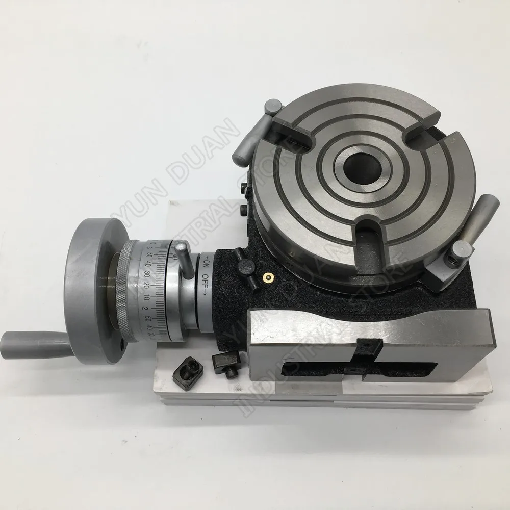
I have one of Warco"s HV4 Rotary Tables which has not been greatly used in the 7+ years I have owned it. However, I want to use the table on an item about 2.5" diameter, held in a mandrel in an ER32 collect chuck. The collet chuck is screwed onto a fitting with a M2 Morse taper into the rotary table. The fitting was turned true in the lathe having been secured to a M2 blank end arbor fitted in a M2 to parallel adaptor and set up to run true, so I was sure this item was good.
Out of interest, having set up the part on the mandrel in the collet chuck on the table I clocked the part which I had just turned true with a DTI. It showed about 0.010" run out of true over the 360 degrees. Checking why, I put a brand new M2 blank end arbor from Arc with a 1.5" diameter end - this I reasoned should - must - run true, it didn"t.
Hi I fitted the rotary table on to a faceplate on the lathe and clocked, with a dial indicator, the outside of the rotary table then I wound the rotary table and it ran true. Next I checked the center bush and it ran out and after setting the angle on compound slide found angle was also out. Using a dremmel mounted on toolpost and a grinding wheel I then trued up the center bush. Problem solved.
I"ve seen it said that generally the centre holes are no harder than the table itself but have no links to authority to back up that statement. I have seen rotary tables with parallel bores showing minor abrasion marks suggesting that they were not hardened.
I did clock the top of the RT, thinking it might have a slight list relative to the mill table, but it was spot-on. I didn"t clock the bore but will do tomorrow - I do hope that it runs true, I don"t fancy having to grind it true, for a start I haven"t seen a grinding wheel on a long enough shaft to put in the Dremmel to get all the way down the bore. Don"t fancy having to machine it with a carbide boring bar either for that matter.
Reams tend to follow the original bore on this type of item, you would have to bore the hole true before reaming you could remove the bush from rotary table and check for concentricity or replace the bush with a new one or make a parrallel bush of any size you like.
If it were mine, I would put the shorter test bar in a four jaw chuck and get it running true with the MT2 end sticking out. Then I would remove the top of the rotary table and fit it on the end of the MT2 bar. A Morse taper extending socket often has a parallel large end and would also chuck up nicely, just zero the runout on the male taper. The bearing inside the RT top could be carefully turned true to the internal MT. Then a bush could be made to run the halves of the table.
My little 4" table has a short parallel 1/2" diameter centre hole at the bottom of which is a tapped hole. This is really useful for holding things down like rod ends for rounding off.
Just a final thought for today - does anyone know how the MT bore is held in a HV4 rotary table, like is it a press fit, secured by adhesive, have a locking screw, whatever else comes to mind?
A rotary table is a precision work positioning device used in metalworking. It enables the operator to drill or cut work at exact intervals around a fixed (usually horizontal or vertical) axis. Some rotary tables allow the use of index plates for indexing operations, and some can also be fitted with dividing plates that enable regular work positioning at divisions for which indexing plates are not available. A rotary fixture used in this fashion is more appropriately called a dividing head (indexing head).
The table shown is a manually operated type. Powered tables under the control of CNC machines are now available, and provide a fourth axis to CNC milling machines. Rotary tables are made with a solid base, which has provision for clamping onto another table or fixture. The actual table is a precision-machined disc to which the work piece is clamped (T slots are generally provided for this purpose). This disc can rotate freely, for indexing, or under the control of a worm (handwheel), with the worm wheel portion being made part of the actual table. High precision tables are driven by backlash compensating duplex worms.
The ratio between worm and table is generally 40:1, 72:1 or 90:1 but may be any ratio that can be easily divided exactly into 360°. This is for ease of use when indexing plates are available. A graduated dial and, often, a vernier scale enable the operator to position the table, and thus the work affixed to it with great accuracy.
Rotary tables are most commonly mounted "flat", with the table rotating around a vertical axis, in the same plane as the cutter of a vertical milling machine. An alternate setup is to mount the rotary table on its end (or mount it "flat" on a 90° angle plate), so that it rotates about a horizontal axis. In this configuration a tailstock can also be used, thus holding the workpiece "between centers."
With the table mounted on a secondary table, the workpiece is accurately centered on the rotary table"s axis, which in turn is centered on the cutting tool"s axis. All three axes are thus coaxial. From this point, the secondary table can be offset in either the X or Y direction to set the cutter the desired distance from the workpiece"s center. This allows concentric machining operations on the workpiece. Placing the workpiece eccentrically a set distance from the center permits more complex curves to be cut. As with other setups on a vertical mill, the milling operation can be either drilling a series of concentric, and possibly equidistant holes, or face or end milling either circular or semicircular shapes and contours.
with the addition of a compound table on top of the rotary table, the user can move the center of rotation to anywhere on the part being cut. This enables an arc to be cut at any place on the part.
Additionally, if converted to stepper motor operation, with a CNC milling machine and a tailstock, a rotary table allows many parts to be made on a mill that otherwise would require a lathe.
Rotary tables have many applications, including being used in the manufacture and inspection process of important elements in aerospace, automation and scientific industries. The use of rotary tables stretches as far as the film and animation industry, being used to obtain accuracy and precision in filming and photography.

Little Machine Shop 1812 Tail Stock for LMS1812 4" Rotary Table Modeled in Solid Edge ST8, rendering done in KeyShot. ...Picture of actual tail stock for reference.
This is a pulley gear that slips over the knob of a Vertex HV-4 rotary table so that the rotary table can be driven by a stepper motor. The gear is 160 tooth and driven by a 20 tooth gear on a stepper motor with 1.8 degree steps. This results in 400...
Hi, This model is a rotary table 4 inches in diameter that can be mounted both horizontaly and verticaly. It is a model that can be purchased in Canada from Busy Bee (part #B2724). I beleive it is also sold under different brand names.
This is a 4-rotor rotary engine. Engines like these aren"t used much in real life, but they do provide a lot of power when used correctly. ...Made with Solidworks 2020, and renderings done (obviously) with Keyshot 9 (watermarks are there since I didn"t...
Simple housing for 4 x rotary potentiometers (In my case WH148 B10k units, widely and cheaply available) with space to fit an Arduino Pro Micro for PC MIDI interface.
Rotary plate version 1 (tacka v1.stl) is better than previous version - is more stable. Now I tested 4 kilograms object - for this rotary table - is no problem. ...
[url]http://www.ebay.com/itm/4-ROTARY-TABLE-NEW-3-28-12-PIC-5794-/231628103620?pt=LH_DefaultDomain_0&hash=item35ee1c5fc4[/url] The mount simply interfaces the Nema 23 to the original shaft. To modify the Rotary table you must turn the shaft down...
Hello everyone this is rotary display table, You can use it to rotate your 3d parts for enhanced viewing, or whatever object you may want to turn the design is simple and for this project you need this things : Hardware parts: 1-All .STL file need to...
Hello everyone this is rotary display table, You can use it to rotate your 3d parts for enhanced viewing, or whatever object you may want to turn see full tutorial from here:https://youtu.be/s3biLYWiKNQ the design is simple and for this project you...

Three-purpose lathe chuck / universal with a set of external OJS and internal IJS jaws and a key Average w: 100 mm Clamping: M3(screws only from the front) Other dimensions and parameters - see attached PDF Accuracy, throwing - see enclosed PDF Other sets of internal and external jaws can be purchased - see related products. The chuck has a lubricator directly on the front of the chuck, we recommend the lubricant oil KV 100 during machining without rinsing or Vaseline Gleit 520HP 520TS / MOGUL CALSUL 2 WR when rinsing. The chuck is delivered in a paper box with a Czech manual. Including sets of Allen screws for clamping only from the front(type M3). Suitable for grinders, dividers, turntables, etc.


 8613371530291