
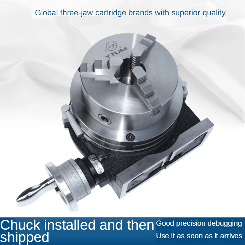
indexing head vs rotary table brands

Dividing heads allow you to divide a circle into equal fractions conveniently. Anything that involves regular action around a circle is a candidate for a dividing head.
A rotary table has no stops so it is not convenient to do large numbers of things at equal intervals because you would have to painstakingly determine the interval. Also, the rotary table does not divide the circle. For example, if you were making 13 equally spaced operations using a rotary table you would have to calculate some wierd angle for each operation and dial it in--a tedious process. For example, here are the 13 angles for a circle division:
Do you want to manually set each of these values? Have fun doing that. Now, imagine doing it for 53 divisions. You will be there all night. Not only that, the error will be a lot more than a dividing head.
I think as rotary table with index plates and a tailstock might be a bit more versatile than a dividing head. You can use its flat table to clamp projects down on,like a face plate. You can add a chuck. You can still cut gear teeth with the dividing attachment. A universal index head can tilt,but a rotary table can too,if you mount it on a tilting table. Less rigid on a tilting table,but I like using the flat table better than other short comings it might have.

Rotary tables are mounted horizontally, and most can also be mounted vertically. In both cases only at 90° to the mill table. A Dividing Head is always vertical, but can be tilted through 90°.
Dividing heads are always fitted with "indexing plates" (holed wheels and clock hands), allowing a wide range of angles to be turned. The indexing mechanism can do intermediate angles. Rotary tables can be fitted with indexing plates as an accessory, but usually the number of angles supported is limited compared to a dividing head. (A generalisation. And, because rotary tables do all common angles, the limitation may not matter.)
Rotary tables are more convenient for general work because most jobs are mounted at 90° or 180° relative to the milling table. Possibly more robust than a dividing head for rough work. When close accuracy isn"t needed, jobs can be spun rapidly by the rotary table without cranking the handle - a time saver. When accuracy is needed the handle and worm are engaged. Usually there"s a vernier scale sufficiently accurate for most work. The handle is also relatively fast because most simple angles can be produced with it. For example, easy to crank from 0, 60, 120, 180, 240, 300, 0 to cut a hexagon head. Unfortunately not all angles are "simple"!
Indexing plates are useful for awkward angles. Cutting a 19 toothed gear requires 19 steps of 18.9474°, which is the hard to remember sequence 37.89, 56.84, 75.78, 94.74, 113.68, 132.63° etc. The Index plate and clock hand mechanism remove the need for the operator to track the sequence but they are still a pain to use in my opinion!
Indexing plates are so awkward that driving a Rotary Table with a stepper motor and microcontroller is popular. You simply tell the controller how many divisions are needed, press "Go", and the computer does the rest. Apart from reducing brain strain and automating a tedious task, the computer eliminates most mistakes. Computers don"t get sums wrong, have excellent memories, and are hard to distract! Also, a computer and stepper motor will do a good job of angles too complicated for the Indexing plates.
Generalising again, I suggest most people, most of the time, only need a rotary table. I see Dividing Heads as specialist tools and have never felt the need for one. For the same reason I drive an ordinary small car rather than a Land Rover. The closest I get to off-road driving is a supermarket car park! You might live on a farm...
Unless there"s a specific reason for needing a Dividing Head, I wouldn"t spend money on one. My rotary table is used a lot, in contrast a Dividing Head is only "nice to have".

I have used it in the vertical position to cut a 107 tooth gear which isn"t covered by any of the dividing head wheels I"ve got. I set up an excel spreadsheet with the angle required for each tooth which isn"t as easy as it sounds as the rotary table is calibrated in degrees/minutes/seconds rather than decimal degrees so it took a bit of figuring out how to do it.

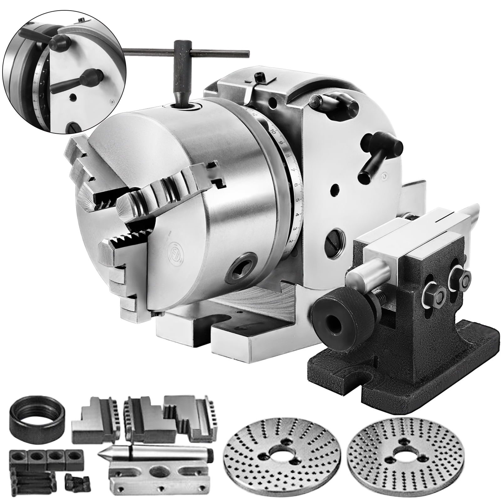
A rotary table is a precision work positioning device used in metalworking. It enables the operator to drill or cut work at exact intervals around a fixed (usually horizontal or vertical) axis. Some rotary tables allow the use of index plates for indexing operations, and some can also be fitted with dividing plates that enable regular work positioning at divisions for which indexing plates are not available. A rotary fixture used in this fashion is more appropriately called a dividing head (indexing head).
The table shown is a manually operated type. Powered tables under the control of CNC machines are now available, and provide a fourth axis to CNC milling machines. Rotary tables are made with a solid base, which has provision for clamping onto another table or fixture. The actual table is a precision-machined disc to which the work piece is clamped (T slots are generally provided for this purpose). This disc can rotate freely, for indexing, or under the control of a worm (handwheel), with the worm wheel portion being made part of the actual table. High precision tables are driven by backlash compensating duplex worms.
The ratio between worm and table is generally 40:1, 72:1 or 90:1 but may be any ratio that can be easily divided exactly into 360°. This is for ease of use when indexing plates are available. A graduated dial and, often, a vernier scale enable the operator to position the table, and thus the work affixed to it with great accuracy.
Rotary tables are most commonly mounted "flat", with the table rotating around a vertical axis, in the same plane as the cutter of a vertical milling machine. An alternate setup is to mount the rotary table on its end (or mount it "flat" on a 90° angle plate), so that it rotates about a horizontal axis. In this configuration a tailstock can also be used, thus holding the workpiece "between centers."
With the table mounted on a secondary table, the workpiece is accurately centered on the rotary table"s axis, which in turn is centered on the cutting tool"s axis. All three axes are thus coaxial. From this point, the secondary table can be offset in either the X or Y direction to set the cutter the desired distance from the workpiece"s center. This allows concentric machining operations on the workpiece. Placing the workpiece eccentrically a set distance from the center permits more complex curves to be cut. As with other setups on a vertical mill, the milling operation can be either drilling a series of concentric, and possibly equidistant holes, or face or end milling either circular or semicircular shapes and contours.
with the addition of a compound table on top of the rotary table, the user can move the center of rotation to anywhere on the part being cut. This enables an arc to be cut at any place on the part.
Additionally, if converted to stepper motor operation, with a CNC milling machine and a tailstock, a rotary table allows many parts to be made on a mill that otherwise would require a lathe.
Rotary tables have many applications, including being used in the manufacture and inspection process of important elements in aerospace, automation and scientific industries. The use of rotary tables stretches as far as the film and animation industry, being used to obtain accuracy and precision in filming and photography.

CNC Indexing & Feeding Technologies is proud to represent the TJR line of rotary tables, indexers and accessories. TJR originated as a rotary table sales and service agent and established itself as an OEM in 2009.
TJR tables feature an anti-wearing worm gear, durable, high-tensile brass shafts, and braking systems with a large clamping range. All new TJR tables come standard with a 3-year parts warranty.
Standard Rotary Tables. The AR Series is TJR’s standard 4th axis pneumatic brake rotary table. It is offered in both a Right hand motor mounting and Left hand motor mounting option. The HR Series is TJR’s standard hydraulic brake 4th axis rotary table.
CNC Indexing & Feeding Technologies offers a wide range of TJR rotary tables. However, many are unclear about what rotary tables can do for their business, as well as how they work in CNC machining. First, let’s consider the basics about a rotary table and how it works in the machining and manufacturing processes.
A lathe or milling machine requires its own set of parts to work sufficiently. For example, an indexing head is needed to allow circular shaping. The indexing element allows the piece to be rotated at an angle or even divided into sections.
A rotary table can tilt and rotate. The table makes use of the indexing head in order to cut according to a specific technique. This makes it possible for the machine to create a workpiece with complete flexibility in rotation and angling.
A rotary table can help to create arcs and circles, an important process in part or tool fabrication. Tools can be specially made, such as car parts, machine parts, and many other objects.
The CNC process lets companies make straight cuts even with multiple angles and to cut small objects into even smaller parts. CNC rotary tables can also help in the processes of cutting gears, drilling or cutting holes.
The table can also be used along with a dividing head and index plate, to further concentrate the shaping. Tables are also used to hold certain parts for superior milling techniques.
Adding rotary tables will improve your capacity to produce the parts you want and increase profits. This brings us to the primary advantage of CNC rotary tables: less time and greater accuracy in cutting.
The benefits of using cnc rotary tables include consistency, faster production and increased capacity. Products and work pieces assembled through CNC systems are more reliable than products created manually or through other methods. The process is identical each and every time, so consistency can be guaranteed. This is critical for a company trying to ensure safety protocol.
The capacity of complexity of product is another benefit. Complex motions are made simpler by CNC rotary tables, making them more affordable to produce.
Naturally, such an intricate process cannot be unsupervised, since efficiency depends on optimal performance. A supervisor must oversee a rotary table operating with CNC controls to ensure the machine and software are configured correctly.
We offer a wide variety of rotary tables to meet all of your needs. This includes standard rotary tables with full rotating axis capabilities, and vertical and horizontal mounting positions.
We also offer large rotary tables with hydraulic brake systems, which allow higher clamping torques. You can also find assistance with smaller rear mount rotary tables or tilt rotary tables.
Horizontal rotary tables are specially made for horizontal mounting and carrying a much heavier weight. Horizontal index tables are available, whether in manual or CNC index tables style. Finally, there are face gear rotary tables and rotary table accessories, ideal for projects that need higher degrees of accuracy.
CNC Indexing & Feeding Technologies can help you find the machine tool accessories you need to meet your production demands. This includes simple rotating feature, larger work pieces, vertical and horizontal applications, or even 4 or 5 axis work. With TJR rotary tables, you can improve your cycle and process time, reduce your down time and increase your profits.

Rotary Tables└ Workholding Supplies└ Workholding & Toolholding└ CNC, Metalworking & Manufacturing└ Business & IndustrialAll CategoriesAntiquesArtBabyBooks & MagazinesBusiness & IndustrialCameras & PhotoCell Phones & AccessoriesClothing, Shoes & AccessoriesCoins & Paper MoneyCollectiblesComputers/Tablets & NetworkingConsumer ElectronicsCraftsDolls & BearsMovies & TVEntertainment MemorabiliaGift Cards & CouponsHealth & BeautyHome & GardenJewelry & WatchesMusicMusical Instruments & GearPet SuppliesPottery & GlassReal EstateSpecialty ServicesSporting GoodsSports Mem, Cards & Fan ShopStampsTickets & ExperiencesToys & HobbiesTravelVideo Games & ConsolesEverything Else

The indexing plate is a machine tool accessory that holds the workpiece on the chuck or between two pinnacles and rotates, indexing and positioning it. Plate connected with rotary indexing table is in Diameter: 7"/180mm and Thickness: 0.47"/12mm, good for rotary tables in Model HV-8, HV-10, HV-12, HV-14, TS200, TS250, TS320, TS400. Perfect to use with dividing head for milling table.

Fig. 4—On this tilting rotary table, one servo controls rotation, another controls tilt. Both servocontrols are slaves to the CNC with RS-232 communication, providing five-axis capability from a standard three-axis CNC.
Fig. 1—Modern rotary tables such as this one from SMW Systems have large, widely spaced spindle bearings, large diameter wormwheels and built-in spindle brakes.
If you want to make parts similar to the complex valve body (upper left), an indexer using M-code, RS-232, or “full fourth axis” control is appropriate. Only positioning and rotary cutting moves are required. The center workpiece is a cam that requires simultaneous rotary and linear moves. You’ll need full four-axis control for such workpieces. If you want to do parts similar to the impeller on the right, the contour cutting will require simultaneous five-axis machining.
On complex workpieces that require machining on surfaces not 90 or 180 degrees from each other, indexing or fourth-axis rotation is almost essential to produce the piece. Even when rectangular workpieces with all surfaces 90 or 180 degrees from each other are put on a tombstone, the HMC’s built-in fourth axis of rotation creates a productivity advantage. This is true even if machining on more than one side of the part is not essential.
Earlier rotary tables and indexers didn’t have the accuracy, rigidity or control flexibility of today’s models. Many shops that tried using indexers in the past had been disappointed in the performance of the older models and abandoned their use in favor of multiple operations, multiple holding fixtures and multiple handlings of the workpiece. They decided that the manual, multiple-operation process was better than trying to use ineffective early model indexers and rotary tables. Today, the situation is different. Manufacturers now offer units that are very accurate, very rigid and have a variety of control and interface options.
Terminology in the area of indexers is not standard. Terms such as fourth axis, indexer, rotary table and so on are used interchangeably by different machine tool and accessory companies. So, when selecting and buying, you must ask a few questions before assuming you know what you’re going to get. Also, beware of terms such as “precision,” “high precision,” “accurate,” and “rigid.” Is the “brake torque” specification some absolute break away spec or the torque at which some “unacceptable” amount of rotary deflection occurs? Is the “ten arc seconds” accuracy specification certified every one degree, or is it inspected only every 15 degrees? There are no industry standards for specifications and testing. So ask questions and deal with a supplier in which you have confidence, or buy with a guarantee of performance to make your parts.
We’ll start with the mechanical hardware and discuss the electronic control options later. There are at least three common mechanical indexer/rotary table types.
These tables provide infinite positioning as well as the possibility of rotary cutting. A servomotor controlled directly either by the CNC or by a secondary servocontrol rotates a wormscrew, which drives a wormwheel on the rotary table spindle.
The absolute position accuracy of these systems is a function of the quality (precision and accuracy) of the wormgear set (wormscrew and wormwheel), the accuracy and resolution of the servosystem, and the means of servoposition feedback. Most of these servosystems utilize an encoder to monitor the position of the motor rather than the rotary spindle directly. To eliminate any inaccuracies in the wormgears and servo system, some high-end systems use a glass scale or other encoder directly on the rotary spindle to monitor actual rotary spindle position. Figure 1 (at right) shows a typical wormgear rotary table cross section.
If controlled directly by the machine tool’s CNC, they are most commonly referred to as a “full fourth axis.” A full fourth axis has the advantages of having only one CNC program, no programming required by the operator on the shop floor, minimum chance of a crash due to operator error, and the ability to make simultaneous rotary and X, Y or Z moves to do true helical milling operations as required by some more exotic workpieces.
Claims of position accuracy are often misleading since there are no industry standards. Although some manufacturers test and certify absolute position accuracy every one degree, most do not state exactly what their specification means.For all except those few expensive systems with glass scales directly on the rotary spindle, any accuracy specification is for a new table before it has been subjected to any “crashes,” which are not uncommon. Even seemingly small crashes can damage wormgear sets.
Typical infinite positioning wormgear systems utilize a friction brake to hold position against cutting forces. When cutting forces are applied directly on the rotary spindle centerline, friction brakes are generally adequate for most work. However, when cutting forces are applied to workpieces far off centerline, such as on the edge of a part on a tombstone fixture, the resulting torque on the rotary spindle can cause it to deflect. This result is especially likely when heavy cuts produce high thrust forces.
Assuming it’s a quality face gear set, absolute position accuracy is superb and is maintained for the life of the indexer almost in spite of any “crashes” that might occur. Units with true absolute angular position accuracy of 5 arc seconds or less are available. These units are ideal for the highest precision work such as line boring half way from one side, then indexing 180 degrees and line boring half way from the other side.
Whether you select an infinite positioning wormgear rotary system or a facegear system as the best mechanical design for your work, your next decision involves how you will control the rotary axis.
If you select a system with a servodrive, you have three choices: 1.) direct “full fourth axis” using only the machine’s CNC, 2.) an M-code command from the CNC to a separate rotary control, or 3.) RS-232 communication between the machine’s CNC and a separate rotary control. Each of these choices has advantages and disadvantages.
The single CNC constantly tracks all three linear axes (X,Y,Z) and the rotary axis. This provides the ability to do precise helical cutting with simultaneous rotary and X, Y or Z moves.
While a few machine builders offer a full four-axis control with rotary table for about 10 percent of the base price of the machine, most charge more than 20 percent.
Very few machine builders make it easy to retrofit a full four-axis rotary table. For most builders, retrofitting is a complicated process, and the cost typically exceeds 30 percent of a base machine price.
The motor for the rotary axis must be matched to the servodrive of the CNC. Because cable connections are not standard from one machine builder to another, rotary tables can not generally be used on more than one machine.
An M-code actuated system provides a fourth axis of motion by combining a standard three-axis CNC with a rotary table or face gear indexer that has its own separate rotary servocontrol. The rotary program is entered and stored in the separate rotary servocontrol. The CNC communicates with the rotary control via an M-code. When the rotary control receives the M-code signal, it executes the next rotary move stored in its memory, then sends a signal back to the CNC, telling it that the move has been completed.
Typically, the rotary program includes many separate rotary moves. One move might be a simple index to position at full rapid speed. Another might be a slower rotary move to machine a groove or other feature on the workpiece. Figure 3 (at right) shows a typical rotary servocontrol system.
High quality M-code controlled systems are available from several suppliers for a price of about 10 percent of a base machine price. (For example, a 5C rotary system at $6,000; a 6-inch faceplate system at $7,000; a 9-inch system at $10,000; and so on).
Systems can be moved from one machine to another as long as the next machine can issue M-codes. A shop with multiple machines and multiple rotary systems can select the best system for each job regardless of the machine. For example, a small indexer can be used for small parts to avoid cutting tool interference problems and to minimize indexing times. A big indexer can be used for big parts. A face gear indexer can be used when the maximum in accuracy and rigidity are needed and the work can be accommodated by multiples of 5 degrees of index.
The machine operator needs to enter the rotary program into the rotary servocontrol, or select the right program if it’s already stored in the rotary control’s memory. This takes some time, and there is the chance of an error.
If the machining cycle is ever interrupted in mid-cycle, such as to inspect a workpiece feature or replace a worn cutting tool, the operator must be sure to back up the rotary program and the CNC program to a point that keeps the two programs in sync. This step can be confusing, and any error can result in a “crash,” with a cutting tool coming down to a workpiece rotated to the wrong position.
Although it is possible to perform simultaneous rotary and X, Y or Z moves, they are not recommended. If you have patience and can afford to scrap a few parts, you can use trial and error to find the right rotary speed to match the linear move and determine starting points that match.
Recently developed, RS-232 communication between a three-axis CNC and a rotary servocontrol offers advantages of full four-axis and M-code operation. RS-232 is the commonly used, standard electrical interface for connecting peripheral devices to a computer. Personal computers often use the RS-232 communication protocol to send information to a printer. Another common use for RS-232 communications is connecting a PC to an external modem.
Nearly all CNC units have an RS-232 port, and it is commonly used to exchange CNC programs between a computer system and the CNC. More recently, RS-232 connections have been used by CNCs to communicate with robots and rotary tables. To communicate with the rotary table’s control, a special line of code is inserted into the CNC program. This line of code sends a string of numbers and letters through the RS-232 port to the rotary table control, which translates the string of code into rotary moves.
RS-232 communication between a three-axis CNC and a rotary servocontrol provides much of the best of both worlds of full four-axis and M-code operation. Both the linear and rotary moves are stored in the CNC as part of the workpiece program. When a rotary move is required, the CNC sends the commands for that one move (rotary speed and angle of rotation) through an RS-232 line to the rotary control.
The rotary control executes that one move and sends back a signal to the CNC, indicating that this move has been completed. The CNC then commands its next linear move. The separate rotary servocontrol simply works as a slave to the CNC. The machine operator turns the rotary control on in the morning and does not need to attend to it the rest of the day. Figure 4 (at right) shows a tilting rotary table system utilizing two rotary servocontrols with RS-232, providing five-axis capability from a standard three-axis CNC.
Crashes are nearly as unlikely as with a full four-axis control. The correct rotary program is always selected because it is part of the total workpiece program stored in the machine’s CNC. Note: Rotary moves should be programmed in “absolute position” so that if the machining cycle is interrupted, the operator can back up the CNC program to just in front of a rotary move, then safely resume the program.
With RS-232, two rotary controls can be operated by most three-axis CNCs with only one RS-232 port. Five-axis capability with a tilting rotary table setup can be retrofitted to a three-axis machine for about $25,000 (a new, full five-axis VMC option is typically priced at $95,000).
Both the work you need to do and the machines you own or intend to purchase will influence what you select for a rotary axis. These guidelines summarize what you should consider.
When buying a new machine, get prices on everything the builder offers, no matter what kind of workpieces you’ll be machining. If the builder offers a full four-axis system with a high-quality, infinite-positioning rotary table at a price of about 10 percent off the base machine, this system will probably be your best choice.
If you’re doing a variety of work that requires simultaneous rotary and linear helical moves, you’ll probably want a true four-axis system regardless of the cost. However, you should consider a more economically priced RS-232 or M-code system when you are retrofitting an existing machine and have only a couple of jobs requiring these moves, especially if these jobs are long run and you can afford some extra programming and setup time. These systems are worth considering if you simply can’t afford the price of a true fourth axis.
If you’re retrofitting existing machines, especially if you have several and want to do rotary work on more then one of them, check with the builder on the cost of upgrading to full four axis. You may conclude that the cost and flexibility advantages of RS-232 or M-code will make one of them the best choice.
Adding a rotary axis to a VMC is worthwhile whether you want to do full four-axis simultaneous machining of exotic workpieces, simple indexing of parts that need machining on surfaces not at 90 degrees from each other, or tombstone processing of rectangular parts that benefit from a longer unmanned machining cycle. Today, many good options exist. If you’re buying a new machine, have the builder quote the optional systems it offers. If you’re going to retrofit an existing machine, contact either the original supplier or the companies that offer complete indexer and rotary table systems. Retrofitting is highly affordable. (Systems from SMW Systems, for example, generally cost a little over $1,000 per inch of faceplate diameter, including installation and training.) MMS
The rotary table indexer is a process in which, after repeated angular displacement during the machine cycle, it comes to a standstill. The rotary indexing table is specially designed to perform repetitive movements around the platform. Basically, these are high-precision work positioning devices that index parts to be machined or machined in multiple operations.
A rotary table indexer, or a rotary indexing table, is an integrated motion system. It usually consists of motors and mechanical power transmission devices along with encoders, sensors, and drivers. The tables use electric motors for cam drives or servo tables. Mechanical cam indexers are relatively cheap and index only for setting angles, but are capable of precise movement.
It is a precision work positioning device used in metalworking that allows the operator to drill or cut at exact intervals around a fixed location (usually horizontal or vertical) axis. Some rotary tables allow the use of index plates for indexing operations, and some can also be fitted with dividing plates that enable regular work positioning at divisions for which indexing plates are not available. A rotary fixture used in this fashion is more appropriately called a dividing head (indexing head).
Important parameters for rotary indexING tables are the required application resolution (or smallest increment to be moved or measured), the required repeatability and accuracy, and other mechanical parameters such as acceptable levels of backlash or hysteresis. Another key parameter is the load including moments, axial, radial, and moment loads. They can affect the type and size of the indexer used in your application.
The rotary indexing table can be used in a wide variety of applications including manufacturing, inspection, and assembly tasks. For example, machines for assembly, processing, and bottling use indexers. They typically take one piece to work areas or move sets of relatively small parts around the station for sequential machining or assembly tasks.
Rotary tables are most often mounted "flat", with the table rotating around a vertical axis, in the same plane as the vertical milling machine. An alternative configuration is to mount the turntable indexer at its end (or mount it "flat" on the plate at a 90 ° angle) so that it pivots about a horizontal axis. A tailstock can also be used in this configuration to hold the workpiece "between centers".
With the table mounted on the auxiliary table, the workpiece is exactly centered on the axis of the rotary table, which in turn is centered on the axis of the cutting tool. So all three axes are coaxial. From now on, the auxiliary table can be moved anywhere X or Y direction to position the cutter at the desired distance from the center of the workpiece. This allows concentric machining operations on the workpiece. Placing the workpiece off-center at a certain distance from the center allows you to cut more complex curves. As with other vertical milling setups, the milling operation can be either drilling a series of concentric and possibly even hole spacing, or face or end milling of circular or semicircular shapes and contours.
With an additional folded table on the turntable, the user can move the center of rotation to any place on the part being cut. This allows the arc to be cut anywhere in the part for cutting round pieces. Additionally, when switching to stepper motor operation with a CNC milling machine and a tailstock, the rotary table indexer allows you to make multiple parts on a milling machine that would otherwise require a lathe.
Rotary tables have many applications, including the manufacturing and inspection of critical components in the aerospace, automation, and science industries. Typical indexing table applications might include:
Virtually any manufacturing operation can be performed on a part held by an indexing table including welding, grinding, drilling, assembly, painting, inspection, testing, and more. In order to maximize operational efficiency, the unit must also be built for the same intended application as the indexing table for them to work in synch. Similarly, the unit that loads the indexing table with parts must also be synchronized. They must have the same capacity and be able to manage to the same dwell time for the system to work.


 8613371530291