
lehmann rotary table pdf free sample

Our customers live in different time zones, speak a variety of languages and need information at different times of the day and night. In the Download area, pL LEHMANN offers a wealth of information at no cost – 24/7 365 days a year.
pL LEHMANN holds the copyright for all data available herein. The brand name pL LEHMANN is internationally protected by copyright. Pictures and diagrams are only intended for the use in promotional documents and technical documentation and only for OEM customers (original equipment manufacturers) of pL LEHMANN. Any other use is subject to copyright terms. In case of doubt, please don’t hesitate to contact us.
Usually, the data is updated on a weekly basis. Possible amendments are agreed with the customer in the case of running orders, provided that these orders are affected by such amendment. pL LEHMANN shall not be liable for any data used prior to placing of orders or after delivery.

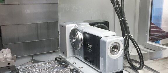
In its production facility, complex parts are machined to high accuracy on a Mazak VCN 530C vertical machining centre and through the addition of a 2-axis CNC rotary table from Switzerland-based Peter Lehmann AG, the company can machine parts on five sides using five axes.
The company has enjoyed a close business relationship with Mazak since 1979 so not surprisingly Loesch"s ground floor houses six Mazak CNC machines – the latest being a 3-axis VCN 530C VMC. Following the purchase, a CNC rotary table combination from Peter Lehmann was added to the set-up to enable 5-axis machining.
However, a true 5-axis machine wasn’t an option for Michael Loesch: “Rocker-mounted rotary tables are usually pretty small – but the alternative was to spend a lot more money on a larger machining centre,” he reveals.
A 3+2-axis approach is less expensive while offering a greater flexibility: “For us the Mazak VCN extended by the Lehmann rotary/tilting table is the perfect solution,” Mr Loesch enthuses. “It even leaves enough room to accommodate two more vices on the machine table, thus providing further clamping options for simpler workpieces.”
To the Loesch team, the 1,300 x 550mm table was of particular importance as it can accommodate the Lehmann CNC rotary table and still provide enough space for two (125mm) vices.
Supported by the Swiss rotary table specialist and German sales and service partner IVO Oesterle, the team selected the T1-510520.RR TOP2 2-axis model. “The Swiss quality won us over from the start,” Mr Loesch recalls. “With regard to performance and suitability for digitalisation and Industry 4.0, we simply didn’t need to consider any alternatives.”
3D CAD data of the CNC rotary table was submitted to the team beforehand, so a matching workspace concept could be established via the in-house CAD system.
The 2-axis Lehmann T1-510520.RR TOP2 rotary table is 711mm long, 301mm wide and 250mm high. It clamps workpieces of up to 340mm in diameter which is more than enough for Loesch which mainly processes small to medium-sized workpieces up to cube edge dimensions of around 150mm.
Precision is also of paramount importance to Loesch. Also, precision is a core value at LOESCH. The indexing accuracy (Pa) specified by Lehmann of ±17 arc/seconds and ±21 arc/seconds (fourth and fifth axis) as well as the average repeat accuracy (Ps) of ±2 arc/seconds respectively were verified Loesch onsite using a calibration cube. The results actually exceeded the specification.
In practice the high positioning speed of the rotary/tilting table is another significant benefit: “If possible we use one single tool, e.g. a chamfer milling cutter, to execute all operations in sequence, turning and tilting the workpiece than repeatedly changing the tool.”
“This required up-front collaboration between Lehmann and the Mazak control system developers but the result was well worth the effort. I can now program our VCN 530C with its 2-axis rotary table just like a 5-axis Mazak Variaxis which reduces programming to a fraction of the time. The productivity gains are significant – particularly for single and small-series parts. Typical batch sizes for us about between 20 and 200 pieces.”
Michael Loesch is very satisfied with his investment: “Thanks to the Mazak VCN 530C, the Lehmann rotary table and the other options we specified, we have made considerable time savings and reduced the effort required for re-clamping, thereby freeing up our machine operators to take care of other tasks,” he states.
Next on the agenda is an automated system to feed the VCN, but the Lehmann rotary table is already ahead of the game because it offers media channels to facilitate the remote control of automatic clamping systems.
“The force clamp on the rotary table is already pneumatically controlled and the two vices on the machine table will then be converted from manual to hydro-pneumatic operation,” Mr Loesch concludes. “This will allow us to fully machine all six sides without any manual intervention. This is definitely the way forward for us.”

for the service technicianWith electrical andpneumatic / hydraulic diagrams for: KAB – Wiring harnesses STANDARD WDF – Wall penetrations STANDARD OEM cablingfor pL LEHMANN product line 500 rotary tableswith PGD gear unit technology
www.lehmann-rotary-tables.comCommiss-Instr+Schemas_STANDARD_DOK-0004-EN(30)_2017-07-03 - Translated document in accordance with MRL 2006/42/EC 1 / 153 GENERAL INFORMATION
1.2 Meaning of signal words and symbols used pL LEHMANN rotary tables are used as a rotary axis in the enclosed machining compartment of machine tools. Despite having been manufactured in compliance with the generally accepted rules of design and manufacture, a rotary axis can pose hazards. The following symbols, signal words and the text that follows draw attention to potential hazards to life and limb. These safety instructions are important and must be observed. However, it is also important to us to prevent possible property damage and also make suggestions for optimal use with the signal words WARNING and NOTICE.
1.3 Signs and Labels There are no permanently attached signs or labels on pL LEHMANN rotary tables regarding the safety of individuals and material. Nevertheless, this label with safety instructions is attached to one of the eyebolts on each piece of equipment prior to shipment:
1.4.1 «Packungsbeilage 500__DOK-0001» Fixed to the rotary table, packed in a plastic bag, on a ring bolt . Contains information for identifying the rotary table and must therefore be retained. Table of contents of the "Packaging insert DOK-0001": 1. Instructions for «smart doc» USB stick 2. (Instructions for download if USB stick is missing) 3. Product registration 4. EC Installation instructions for incomplete machines (MRL 2006/42/EC, Appendix II, sub. B). The system number (Serial No.) is visible here 5. Assembly instructions (MRL 2006/42/EC, Art.13 (1) and Annex VI)
1.4.2 Detailed «smart doc» system documentation for commissioning, operation, maintenance, … Saved on the USB stick and attached (protected from water and dirt) to the motor cover on the system. The data storage medium contains the following documents at a minimum: «ADAT - DRIVE SET-UP DATA» Techn. data for this system «PARA-…» Parameter list for the CNC control system supplied «Operating manual STANDARD, DOK-0003» «Commissioning manual STANDARD, DOK-0004» «Commissioning manual, specific», e.g. SEP brother Indexing accuracy report to VDI/DGQ 3441. On T-systems, 1 report each for divider and swiveller / tilter «Geometry test report». Acceptance data after final assembly «PROFI-Catalog CNC Rotary Tables» overview. One each in German and English Special drawings from customer if available Operating manuals for accessories such as hydraulic unit, CNC-FANUC, etc.
1.4.3 Website www.lehmann-rotary-tables.com All documents and information that are not provided are available on the website. A few examples:
The file boxes with machine tool names are empty. However, detailed instructions for the construction, cabling, commissioning and parameterization of pL- LEHMANN systems are available for these machines. Some even with a switchboard expansion with «servoPACK». The corresponding instructions are provided on the USB stick of the system.
1.6 Product registration / Activating the warranty Your pL LEHMANN CNC rotary table was manufactured with great care and to international standards. The warranty for this product becomes effective upon commissioning at the end customer. The warranty period is limited, however, as far as the machine supplier is concerned. Consult them in case questions arise.
1.6.1 Registration requirement The product must be registered within one week of commissioning. pL LEHMANN reserves the right to reject warranty claims on products that are NOT registered, registered LATE or INCORRECTLY registered. The product can be registered either by submitting the form «Activation of the warranty» in the package insert or at http://www.lehmann-rotary-tables.com «Product registration».
1.7 Modification, changes Modifications and changes to pL LEHMANN rotary table systems are prohibited without our written approval.
1.8 Safety Information The following safety information applies to pL LEHMANN systems independently of the ultimately binding overall documentation for the complete machine.
CAUTION Suspended systems can fall. Risk of injury! Never stand under suspended rotary table systems during transport. Always use proper lifting equipment. Put the load down when leaving the workplace.
CAUTION Scissor effect when moving the indexing or tilting axis. Risk of entanglement! Always close safety door when working! Non-round parts on the rotary table spindle can behave like shears. When formless loads are moved on the tilting axis, varying spaces are created. Remove tools, measuring and test equipment, etc. out of the system"s range of movement.
CAUTION The EMERGENCY STOP circuit must stop the pL LEHMANN system. Continued operation of an axis after an EMERGENCY STOP is prohibited! Regulations require that the drive of the rotary axis (axes) be incorporated into the EMERGENCY STOP circuit. As commissioning technician, you are responsible for checking and ensuring compliance.
NOTE Follow the instructions in the OPERATING MANUAL of the «COMPLETE MACHINE». This commissioning manual for the pL LEHMANN rotary table is a lower-order part of the overall documentation of the «complete machine»! Nevertheless, this COMMISSIONING MANUAL applies in its entirety. Because pL LEHMANN rotary tables always represent additional CNC axes incorporated into a machine tool, the are considered to be an «incomplete machine» in accordance with MRL 2006/42/EC. It is the responsibility of the manufacturer of the «complete machine» to prepare an OPERATING manual in compliance with MRL 2006/42/EC. In this respect, this commissioning manual is provided as a service. When an auxiliary CNC control system is used, consult the instructions for this auxiliary control system.
1.11 Original instructions / translations All documentation will be written in the official EU language of German and marked as "Original instructions". For additional languages, see www.lehmann-rotary-tables.com The machine manufacturer or end customer is responsible for additional translations. All translations must be marked with «Translation of original instructions».
1.12 Machine Requirements Integr.: For the integration of 1st/2nd rotary axis SEP: For the integration of the pL servoPACK (Brother, Hurco) FAN: For linking the pL «FANUC CNC control system» via M-functions
NOTE Personnel qualifications. Trained professionals are required for the commissioning of a rotary axis! Training is the responsibility of the manufacturer of the «complete machine». pL LEHMANN offers training at different levels for service technicians. For first-time commissioning in your facility, we recommend commissioning by a technician from pL LEHMANN or one of our contract partners.
CAUTION Suspended systems can fall. Risk of injury! Never stand under suspended rotary table systems during transport. Always use proper lifting equipment. Put the load down when leaving the workplace.
ATTENTION Compressed air at least 4 bar at flow rate of 130 L / min. The clamping does not function below 4 bar! The rotary table displays the error message «clamped» and the system cannot operate. The error message is visible on the red LED "ERROR" on the motor cover. The target pressure ist 5-6 bar. A lower pressure also means a clamping force reduction. Make sure the air supply : The pressure must hold 4 bar min. at a flow rate of 130 L / min.
ATTENTION Only use pL LEHMANN oil, VULCOGEAR V5. Otherwise, the warranty will be invalidated immediately! VULCOGEAR V5 was developed specifically for the very demanding requirements of pL LEHMANN gear units. It must not be mixed with other products. Ensure that your maintenance service receives this information.
2.6 For better air pressure (Option) Flawless and stable air pressure is essential to safe operation and long system life. We recommend the following additional devices, when needed
3 COMMISSIONINGTable of Contents3.1 General Information ................................................................................................................................................ 25
3.7 STEP 6: Specify and enter the axis names and directions of rotation ....................................................................... 29 3.7.1 EA-xxx.L and EA-xxx.R ................................................................................................................................................. 29 3.7.2 T1-xxxxxx.LL ................................................................................................................................................................ 30 3.7.3 T1-xxxxxx.LR ................................................................................................................................................................ 30 3.7.4 T1-xxxxxx.RL ................................................................................................................................................................ 31 3.7.5 T1-xxxxxx.RR ............................................................................................................................................................... 32 3.7.6 Axis names and directions for profile grinding machine ............................................................................................ 32 3.7.7 Zero position: Divider in vertical position ................................................................................................................... 33 3.7.8 Kinematics of all pL LEHMANN drives ......................................................................................................................... 33
4.6 Technical information «blackBOX» - the rotary table electronics ............................................................................ 54 4.6.1 Meaning of LED ........................................................................................................................................................... 55 4.6.2 Features of the blackBOX............................................................................................................................................ 55
NOTE Responsibility The manufacturer of the «complete machine» is responsible for initial assembly and commissioning. The enclosed «Assembly Instruction» according to 2006/42 / EC must be observed. We recommend the use of a pL LEHMANN technician or VAR.
4. Note 1: Control of the outputs has already been optimized with regard to timing by the «blackBOX» rotary table electronics. 5. Note 2: The «blackBOX» permanently checks the clamping even after "clamped" or "unclamped" is displayed.
Measure concentricity (run-out) of spindle. Mark the highest point, Note values and take into account when aligning the pL LEHMANN system.
Measure the geometry of X, Y and Z. Clamp dial indicator in machine spindle for this purpose. The angularity of Z must be measured on the X AND Y sides of the reference cube. Note values and take into account when aligning the pL LEHMANN system.
3.6 STEP 5: Position system, provisionally align and fix in place 1. Place the machine on the machine table and locate the ideal position. NOTE: This also partly determines the names and direction of rotation of the round axes. 2. Distribute the clamping claws according to «Arrangement of the clamping claws» in «Operating instructions STANDARD, DOK-0003», chapter 2.1, from page 16. 3. This is important with regard to the accuracy of the system. With this arrangement, the geometry protocol was also created in the plant. 4. Now tighten the fastening screws only temporarily. The system is then precisely aligned under STEP 11. 5. Connect the cabling.
3.7 STEP 6: Specify and enter the axis names and directions of rotation The following images of various pL LEHMANN systems in different positions on the machine table show the axis names and the rotational direction of the spindles as defined in DIN 66 217. Motor mounted on left = L = green, Motor mounted on right = R = pink IMPORTANT: Keep in mind that the rotational direction of the spindles changes when the rotary table is positioned on the other side of the machine table.
NOTE We describe the rotational direction of the spindle and of the workpiece, respectively. In programming systems, the motion of the tool is usually considered instead. For rotary tables, it has been found beneficial to indicate the rotational direction of the spindle.
3.8 STEP 7: Enter parameters, allow axis to rotate3.8.1 Download and enter parameters Use the parameter lists at www.lehmann-rotary-tables.com On our website you will find continuously updated parameter lists, which we provide free of charge. Click Download/Commissioning/Parameter lists.
ATTENTION Risk of mechanical collision! This can damage the worm gear! Check the following points and reduce if necessary the speed! Are the signals of the limit switches available? Observe LEDs on the engine cover. Responds the PLC correctly to these signals? Remember that the slowing space of the engine at full speed can be longer (up to 30 °) as the possible stopping distance. Of all the systems can be affected. Particularly but the guy OLL or ORR (engine above. See picture). Even large chuck or workpieces may collide with the system. Limiting the travel if necessary with the software limit switches. NOTE 1: Only T systems have hardware range limit switch. NOTE 2: The hardware limit switches are not adjustable. Do not adjust the cam ring. NOTE 3: At www.lehmann-rotary-tables.com Download/PLC/…Guideline… you will find PLC examples where only the first-operated limit switch is evaluated. So you can go away at any time. Even if both limit switches are active. NOTE 4: If the direction of rotation of the rotary table with parameters is changed, the limit switch inputs END1 / END2 must be crossed out. Exception: If only one limit switch input is evaluated by the PLC. Then can END1 and END2 be connected electronically to the black box. NOTE 5: The outputs of the limit set by default as an opener. Adjustable to the black box.
ATTENTION The zero impuls of the motor encoder system could arrive in the same moment as the signal of the reference point sensor. In this case the reference point can float about 1 motor rotation, depending whitch signal will arrive earlier. Run the reference point several times and check the ever same and correct zero position. If necessary, move the came ring on the spindel of the rotary table a little, maximum the half of the way of a motor turn. More instructions see chapter 5.2.1 «Zero position of the spindle».
3.11 STEP 10: Test of spindle clamping (each axis) Proper operation of clamping was ensured above. CAUTION: CNC or PLC/SPS controls do not always correctly manage the «Positioning rotary axis WITH CLAMPING» process. The following malfunction has been observed several times and has very bad impact : The control system deletes the lag error simultaneously with shutting down motor control. The result is slow and unnoticed shifting of the zero point – and workpiece! CORRECT IS: The motor must control the axis all the way to its target position and hold there until the clamping has full clamped. The lag error memory must never be deleted.
All housings are prepared in Milled partial surface for venting: EA rotary table (single modul): this way: The plug GK.42 has a surface that (1)" Closed against contamination. (1)" Pessure of oil 220bar. allows air to escape rapidly during (2)" Closed against contamination. (2)" Locking plug GK.42. venting. Therefore, it must also be (3)" Closed against 220bar. (4)" Threaded hole as parking for at the top during the venting GK.41 if not used.. process.
3.11.8 Clamping force reduction due to counter bearing Maximum length: Measuring tube 1.5m, steel tube 2m, otherwise contact the supplier. The elasticity of the flex or steel tube loads the stroke reserve of the pressure unit BRAKY. Very good venting is therefore important! Particularly important for systems 507 and 520. When the piston stroke is fully utilized, the clamping force on the counter bearing and the rotary table is reduced as well!
5. Parameterize slope error1 (OPTIONAL) 6. Complete the «Geometry acceptance a) Drive to -90 ° report» b) Measure position errors c) Enter linear errors in the rising error table In the case of an intervention by the «Technical (parameterize) Service», all tolerances for aligning the system are to d) Check at 0 ° and -90 ° be taken from the «Abnahmeprotokoll Geometrie / 1 = «Rising error», also referred to as «pitch error» or Geometry acceptance report» (DOK-0214). «spindle slope correction». Also the final measurements shall be carried out and Corresponds to the pitch error per length of a ball documented in accordance with instructions in this screw. Comparable with value 11 and auxiliary mass 1 document. of «Test protocol geometry / Geometry test report».
3.14 STEP 13: Create a backup Now run the backup. Then, in the case of disturbances, the rotary table parameters are also retained. The same also applies after service work on the system. The data backup remains in your own responsibility.
3.15.2 Recommended cycle for stress test (ED 20%-1min) Only permitted after warm-up. Maximum spindle load per «Standard spindle load» in the pL LEHMANN main catalog. Clamp spindle clamping after each positioning. Cycle for rotary axis: Feed 100%: 10x (+180° / pause 4x the time for run 180° (see main catalog), then repeat at -180°). Cycle for tilting axis: Feed 100%: 20x (0° / pause 4x the time for run 180° (see catalog pL), then -90°).
3.16.3 DOK-0301 « Maintenance Recommendation» and «Maintenance Journal» The following document is enclosed by the package insert by all deliverys of new rotary tables.
ATTENTION MAXIMUM RUN TIME 12 SECONDES – NO PERMANENT OPERATION ALLOWED Otherwise, the worm gear can be destroyed by overheating! Run the rotary table for max 12 sec at max speed, especially when the module is cold. Otherwise, the gear can be destroyed by different material extensions.
ATTENTION MAXIMUM RUN TIME 12 SECONDES – NO PERMANENT OPERATION ALLOWED Otherwise, the worm gear can be destroyed by overheating! Run the rotary table for max 12 sec at max speed, especially when the module is cold. Otherwise, the gear can be destroyed by different material extensions.
4.3 Our measuring procedure for the accuracy We carefully measure and record all rotary table modules after finishing. As measuring equipment serve a HEIDENHAIN ROD 800 with coupling K 15. The measuring procedure is based on VDI/DGQ 3441 or ISO 230-2. Measured after the rotary table has warmed up as follow: Warm up: 5 cycles with 24 steps to +15° and 24 steps to -15° with 3 sec break between steps. Procedure for subsequent measuring: 5 cycles with 24 measuring points spaced 15° apart. With these data: o Acceleration 500°/s2 o Feedrate 1000°/min o Ambient temperature approx. 22° o Unloaded spindle Applies only to indexing axes. Without toothed belt drive system.
4.6 Technical information «blackBOX» - the rotary table electronics The electronics unit controls and monitors the system. It is located below the motor cover.
Evaluation and output of the reference signal. The output signal is adjustable. Adjustable in terms of NOC/NCC by means of «black- 9 REF yellow Standard BOXcom.exe» software, in term of PNP-/NPN logic by means of ca- bling.
Evaluation and output of the range switch plus/minus. The signals are not adjustable. Adjustable in terms of NOC/NCC by END1 green 10 Standard means of «blackBOXcom.exe» software, in term of PNP-/NPN logic END2 green by means of cabling.
4.8 Meaning of the LED red «ERROR» In the event of a fault, the red «ERROR» LED flashes continuously. When there are several errors, the flashing code for the next error follows after a pause of 3 seconds, and so on. The errors do not appear according to their importance, but in ascending order. For some errors, the rotary table can continue to work; in others the signal «READY» goes to 0V and requires the rotary table to be switched off. See table. Action: Call technician for machine maintenance. Example for LED red «ERROR»: Blink code series for «Rel. Humidity (2) AND «Vacuum housing» (4)
4.9 Meaning of the LED yellow «SERVICE» If necessary for "SERVICE", the corresponding code flashes continuously. For further instructions see "Maintenance Recommendation" and "Maintenance Journal" DOK- 0301 which was included with the package insert. It is also stored on the USB stick of the pL rotary table. The always tracked document must be stored during machine maintenance.
Table of flashing codes of the yellow LED «SERVICE» If flashing, refer to the instructions in document DOK-0301 "Maintenance Recommendation" and "Maintenance Journal".
Rotary table «ON» Set number of «operating hours» exceeded 2 Drehtisch «EIN» The counter starts when the blackBOX is "on".
For reasons of accessibility on the rotary table, only short USB sticks can be used. On delivery, one USB stick with the system data is inserted in this connector port. For more information in this regard see chapter 1.
4.10 Zero position of the spindle as well as orientation OPT and ZUBThe initial position «0°» is taken when mounting a rotary table modul, as well for mounting options and acces-sories. Not to be confused with the reference point an the limit switches. The cam ring can be rotated on thespindle.
No Malfunction Cause Measure Who(*) Gear unit friction too high or gear Gear unit damaged from collision1. Repair by VAR. (1) PASE unit jamming. or moving with clamped spindle. Motor quickly in overcurrent, wrong PTME2. Cam ring blocked. See images below. reference point. (@EA) Oil pressure in maintenance unit at a. Oil pressure too high. PTME 0.3 ... Set to 0.5 bar.3. Oil loss on spindle or worm gear. Seal defective, clamping ring not b. Repair by VAR. PASE tight. a. Air supply interrupted. Set to 6 bar on maintenance unit. PTME b. No clamping signal. Check signal source and path. PTSE c. Maintenance unit is empty. Refill oil, bleed system. PTME4. Spindle clamping does not clamp. Oil pressure regulator is set to 0 Oil pressure in maintenance unit at d. PTME bar. 0.3 ... Set to 0.5 bar. e. Kink in oil hose. Eliminate. PTME f. Air in hydraulic system. Bleed. PTME5. Spindle clamping does not release. Disturbances on blackBOX cable. Check connection of shields. PTSE Rotary table not connected Check plug on interface to the a. PTSE6. Workpiece spindle does not rotate. correctly. machine. b. Malfunction in CNC control. Evaluate error messages. PTSE7. Gear unit stuck. Maintenance unit is empty. Repair by VAR. PASE Rotary table runs slightly too far PTME8. Toothed belt damaged. Repair by VAR. when moving approximately > 60°. (@EA) U-V-W phases connected9. Motor does not rotate. Correct. PTSE incorrectly. a. Gear backlash. Program backlash compensation. PTSE Position approached10. b. WMS mounted by VAR. PTSE forward/backward has deviation. c. Transmission ratio incorrect Repair by VAR. PTME a. Loose cam washer. Tighten screws PTME Reference point not found or11. The signal edge of ref and zero Rotate cam ring on spindle approx sometimes offset. b. PTME pulse of encoder are too close. 1-2mm. a. BRAKY error PTME «clamped» signal released after12. Hydraulic fitting at base plate Remove system from machine about 20 sec. b. PTME leaking. table. Tighten fittings. «clamp» and «unclamped» signal Earthing connection not clean.13. Consult VAR. PASE sometimes flicker. Shield not connected. The motor rotates but the spindle14. Motor shaft broken. Repair by VAR. PTME does not move. Clamping unclamped increasingly Air outlet at the bottom of the15. Clean. PTME slowly. housing is clogged. «clamped» signal sometimes fails to16. Air in system. Bleed. PTME appear. «clamped» signal sometimes Air pressure briefly drops below17. Repair hall air supply line. PTME disappears briefly and then returns. the limit value. (1)= VAR = Ihr Landesvertreter. Siehe www.lehmann-rotary-tables.com/de/Kontakt/vertretungen/ (*) = PTME = pL trained maintenance engineer for Enduser PTSE = pL trained service engineer for OEM PASE = pL authorized service engineer (freelancer from VAR) PCSE = pL certified service engineer
Keep motions of the flexible tubing in mind at MAXIMUM TABLE MOTIONS. The bending radius must not be less than 100 mm even at the extreme positions.
6.3.3 Coding of cable connectors and device couplings «K8» Single axes (EA-5xx) are always coded as «1st rotary axis». The dividing / indexing axis on T-systems (Tx-5xx5xx, 360° motion) is always coded as «1st rotary axis». The swivelling / tilting axis on T-systems (Tx-5xx5xx, limited range of motion) is always coded as «2nd rotary axis».
8 DIAGRAMS OVERVIEW - all electrical diagrams The following tables contain all current standard and OEM wiring harnesses and all standard wall penetrations with the associated diagrams. The machine-specific servoPACK solutions are not listed. These are documented in separate manuals. See at www.lehmann-rotary-table.com The page numbers are active. Use the «Jump to page» function.
9 Electrical – STANDARD cabling diagramsTable of Contents9.1 Diagrams for wall penetrations WDF with HARTING «K8» & free cable «o» ........................................................... 88 9.1.1 WDF.Fx-K(w)-2 and WDF.Fx-S(w)-2 – for FANUC () ................................................................................................. 88 9.1.2 WDF.M1-K-2 and WDF.M1-S-2 – for MAVILOR ERN incr. (SIEMENS+HEIDENHAIN) ()............................................ 89 9.1.3 WDF.M2-K-2 and WDF.M2-S-2 – for MAVILOR EQN abs. (SIEMENS+HEIDENHAIN) ()............................................ 90 9.1.4 WDF.MI1-K(w)-2 and WDF.MI1-S(w)-2 – for MITSUBISHI HF-KP................................................................................ 91 9.1.5 WDF.Fx-R1x-2 – for FANUC _i,is (F3) and _i,is (F4) ................................................................................................ 92 9.1.6 WDF.M2-R1x-S-2 – for motor MAVILOR/SIEMENS absolut coded (EQN) ................................................................... 93
9.9 Diagrams for CNC controls systems from pL LEHMANN ......................................................................................... 127 9.9.1 pL LEHMANN CNC «FANUC PMi» and «FANUC 35iB» – KAB.Fx-x.x-K8x-2 ............................................................... 127 9.9.2 Interface of pL LEHMANN CNC «FANUC PMi» and «FANUC 35iB» .......................................................................... 128 9.9.3 pL LEHMANN CNC «ModulaNC» - KAB.M1-x.x-MNC-2 ............................................................................................. 129 9.9.4 pL LEHMANN CNC «CPS» with cabling Han42DD - KAB.Y3-x.x-CPS-2 ....................................................................... 130
10 DIAGRAMS for OEM electrical cablingTable of Contents10.1 DMG MORI ............................................................................................................................................................ 13210.1.1 KAB.F3-x.x-DMa-2 – for DMC-xx35V with pL EA-5xx .............................................................................................. 13210.1.2 Option WMS 1Vpp for: 121.026a ........................................................................................................................... 13310.1.3 KAB.M1-1.7-DMb-2 – for DMF; DMU-50/70, -60/80; for pL EA-5xx ....................................................................... 13410.1.4 KAB.M1-1.7-DMb2-2 – for DMF; DMU-50/70, -60/80; for pL tilter ........................................................................ 13510.1.5 Option WMS 1Vpp-EnDat_02 for: STE.DMb........................................................................................................... 13610.2 WALTER MEIER - MATO ......................................................................................................................................... 13710.2.1 WDF.Fx-K(w)-MAa – for CNC-FANUC ..................................................................................................................... 13710.2.2 WDF.Mx-K(w)-MAa – for CNC-HEIDENHAIN iTNC530 ............................................................................................ 13810.3 MIKRON ................................................................................................................................................................ 13910.3.1 KAB.M1-x.x-MIa-2 – for machine VCP_600/800 .................................................................................................... 13910.3.2 KAB.M1-x.x-MIb-2 – for machine VCE ................................................................................................................... 14010.3.3 KAB.M1-x.x-MIc-2 – for machine HSM and HPM ................................................................................................... 14110.3.4 KAB.M1-x.x-MId-2, Dividing axis – for machine HSM and LP ................................................................................. 14210.3.5 KAB.M1-x.x-MId2-2, Tiliting axis without WMS – for machine HSM and LP ........................................................... 14310.3.6 KAB.M1-x.xw-MId2-2, Tiliting axis with WMS – for machine HSM and LP ............................................................. 14410.3.7 KAB.Y2-x.x-MIc-2 [and] KAB.Y2a-x.x-MIc-2 – for Mot. YASK. SGMJV-08 (Y2) SGMJV-04 (Y2a) ............................... 14510.4 BLOHM – KAB.M1-x.x-BLO-2 ................................................................................................................................. 14610.5 SCHAUBLIN SPEZ.KAB-SCa-2 – special assignment KAB.Fx-x.x-R1 .......................................................................... 14710.6 MATSUURA - KAB.Fx-x.x-MTx-2............................................................................................................................. 14810.7 OKUMA - KAB.OK-x.x-Rx-2 .................................................................................................................................... 14910.8 Akira-Seiki ............................................................................................................................................................. 15010.9 BFW....................................................................................................................................................................... 15010.10 Brother .................................................................................................................................................................. 15010.11 DMGMori .............................................................................................................................................................. 15010.12 DOOSAN ................................................................................................................................................................ 15010.13 Fanuc ROBODRILL .................................................................................................................................................. 15110.14 HAAS USA .............................................................................................................................................................. 15110.15 HURCO .................................................................................................................................................................. 15110.16 HYUNDAI ............................................................................................................................................................... 15110.17 MAKINO ................................................................................................................................................................ 15210.18 MAZAK .................................................................................................................................................................. 15210.19 QUASER ................................................................................................................................................................. 15210.20 TONGTAI ............................................................................................................................................................... 15210.21 OKUMA ................................................................................................................................................................. 152
11 Contact Manufacturer: Peter Lehmann AG Bäraustrasse 43 CH-3552 Bärau +41 (0)34 409 66 66 +41 (0)34 409 66 00 pls@plehmann.com www.lehmann-rotary-tables.com
A rotary table is a precision work positioning device used in metalworking. It enables the operator to drill or cut work at exact intervals around a fixed (usually horizontal or vertical) axis. Some rotary tables allow the use of index plates for indexing operations, and some can also be fitted with dividing plates that enable regular work positioning at divisions for which indexing plates are not available. A rotary fixture used in this fashion is more appropriately called a dividing head (indexing head).
The table shown is a manually operated type. Powered tables under the control of CNC machines are now available, and provide a fourth axis to CNC milling machines. Rotary tables are made with a solid base, which has provision for clamping onto another table or fixture. The actual table is a precision-machined disc to which the work piece is clamped (T slots are generally provided for this purpose). This disc can rotate freely, for indexing, or under the control of a worm (handwheel), with the worm wheel portion being made part of the actual table. High precision tables are driven by backlash compensating duplex worms.
The ratio between worm and table is generally 40:1, 72:1 or 90:1 but may be any ratio that can be easily divided exactly into 360°. This is for ease of use when indexing plates are available. A graduated dial and, often, a vernier scale enable the operator to position the table, and thus the work affixed to it with great accuracy.
Rotary tables are most commonly mounted "flat", with the table rotating around a vertical axis, in the same plane as the cutter of a vertical milling machine. An alternate setup is to mount the rotary table on its end (or mount it "flat" on a 90° angle plate), so that it rotates about a horizontal axis. In this configuration a tailstock can also be used, thus holding the workpiece "between centers."
With the table mounted on a secondary table, the workpiece is accurately centered on the rotary table"s axis, which in turn is centered on the cutting tool"s axis. All three axes are thus coaxial. From this point, the secondary table can be offset in either the X or Y direction to set the cutter the desired distance from the workpiece"s center. This allows concentric machining operations on the workpiece. Placing the workpiece eccentrically a set distance from the center permits more complex curves to be cut. As with other setups on a vertical mill, the milling operation can be either drilling a series of concentric, and possibly equidistant holes, or face or end milling either circular or semicircular shapes and contours.
with the addition of a compound table on top of the rotary table, the user can move the center of rotation to anywhere on the part being cut. This enables an arc to be cut at any place on the part.
Additionally, if converted to stepper motor operation, with a CNC milling machine and a tailstock, a rotary table allows many parts to be made on a mill that otherwise would require a lathe.
Rotary tables have many applications, including being used in the manufacture and inspection process of important elements in aerospace, automation and scientific industries. The use of rotary tables stretches as far as the film and animation industry, being used to obtain accuracy and precision in filming and photography.

The Lehmann EA-510 is probably the most popular device in the range with a centre height of 150mm and a spindle nose of 80mm which can accept a whole host of accessories directly and is delivered as standard with an HSK-A63 spindle. There are options of increased precision gear versions, raised centre height to 180mm, various chucking options and rotary couplings to meet any demand, so please contact our technical department to discuss your exact requirements. This device in the first instance is a vertical and horizontal device with the motor mounted to the left hand side, (right hand motor option is available), there are options for a raised backmount motor, which can be found under product code EA-510. OL. An excellent carrying capacity of 200kg vertically and 400kg between centres and speeds up to 80rpm dependent on motor selection. The Lehmann EA-510 CNC rotary table without motor, can be prepared to suit any interface at additional cost – see our interface listings for details and costs for “external interface” which includes motor, switch, cable and connector requirements ;(if you already have a “4th axis interface” in the machine) ;and machine interface costs ;(if you do not have the additional axis fitted). Motor is mounted to the left hand side on this device and may restrict the Y axis capability in certain circumstances, the centre hole of 46. 55mm around 80mm deep ; and a through hole of 34mm is available should you want to machine long bar components that need to be mounted through the centre. A right sided motor mount version is availableThe Lehmann products now come fitted with their own “Lehmann blackBOX” which allows for instant user monitoring of the device, showing the status of all switches, valves, the 24V supply condition and a service light advises when the device requires a service. In addition, remote monitoring is possible via a USB connection. The Lehmann devices are modular and can therefore be constructed as multi-spindle devices or built into 5 axis assemblies in various configurations.

pL LEHMANN has developed a rotary table program optimized for measurement technology – the MQ series. The Swiss manufacturer offers two distinctly different models, the "Q-Line" and the "M-Line". While the "Q-Line" can be retrofitted to almost any measuring device at any time and automated if required, the "M-Line" is available from the measuring machine manufacturer (OEM) as a fully integrated model.
The Q-Line is ideal for stand-alone use. It is suitable for both new and retrofit equipment of coordinate measuring machines (CMM), for example, from all established manufacturers and also of other measuring devices (for roundness, contour, surface...), which it transforms into versatile measuring stations.
As an entry-level model – suitable for simple applications on the shop floor or in measurement laboratory – pL LEHMANN offers the manual, super-flexible rotary table MA-508.m Q. It can be combined with height, contour, and surface measuring devices and is recommended for run-out test equipment and coordinate measuring machines. Users can set different ratios to fast or slow in just a few steps. A smooth-running, sensitive handwheel makes it possible to approach any position very precisely and unerringly. A fold-out digital display shows the angular position with a resolution of 0.001°.
pL Q-Line rotary tables are optionally available in a housing made of aluminum (e.g. for transmitted light systems) or of spheroidal graphite iron (e.g. for CMMs). In addition, each unit is equipped with an emergency stop switch to meet the high safety requirements.


 8613371530291