
using a rotary table on a mill supplier

Years ago, before I learned CNC, I owned a Phase II 8″ horizontal/vertical rotary table that I purchased from Kap Pullen’s Getmachinetools.com store. He has them at a good price, BTW, and he’s a darned nice fellow to deal with as well as being a frequent HSM contributor. Anyway, its a nice little table, but I hadn’t done a whole lot with it for quite a while after purchasing it. As is so often the case, one day, a project landed on my doorstep and I was glad to have it.
Before I could get started, however, I had to make some accessories for it. Basically, I needed some T-Nuts to fit the table, as well as a little fixture that makes it easy to hold a plate up off the table through a hole in the center so you can machine it. The latter, what I call a “plate machining fixture”, was inspired by something similar I saw the Widgitmaster of CNCZone fame using to make Dremel clamps for his mini-router:
The Plate Maching Fixture and 3 Homemade T-Nuts. T-Nuts are easy to make: square a block to the proper dimensions, mill the side reliefs, drill, and tap. These are much smaller than the mill’s Bridgeport standard T-slots, so I made them myself and I’m using 1/4-20 bolts with them. They’re made of mild steel.
I turned the round spigot using the 4-jaw on the lathe. I’m making the fixture out of MIC-6 aluminum plate, which is pre-ground very flat on the sides. This is a 5 inch by 3 inch piece. I’ve clamped it to the rotab using my T-nuts and the regular mill clamps and step blocks. It is sitting on parallels to make sure I don’t cut into the table. You can also see how I’ve clamped the rotary table to the mill table using a big cast iron V-block I have. You can never have to many blocks with precision faces hanging around!
Having a 4-jaw chuck on your rotary table is mighty handy! Because it’s a 4-jaw, you can dial in the workpiece by adjusting the jaws until it is perfectly concentric with the table’s axis of rotation. The best way is to make an adapter plate that attaches to the back of the chuck in the same way that your lathe does so you can exchange lathe tooling with the rotab. Here is an example:
For the example, the chuck is threaded onto the adaptor plate, and then the holes in the adapter plate’s flange are used to bolt down to T-nuts on the table.
In my case, I bought a 4-jaw from Shars brand new, and simply drilled some through-holes in the chuck to mount to the table directly without an adapter plate:
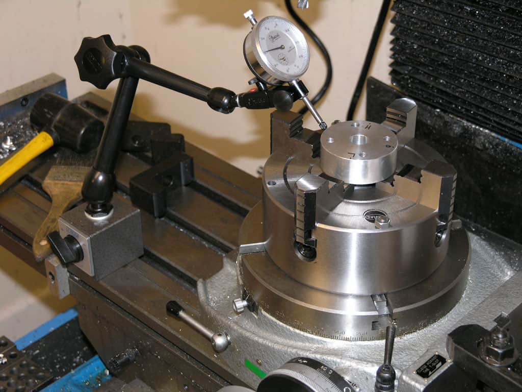
First, you want to make sure your part is properly centered on the table. To do that, I clamp the table down on the mill table (no special place is needed), put my Indicol indicator holder on the mill spindle, and find some round feature on the part to indicate on. For example, on the plate milling fixture above, indicate on the round boss, or on the center hole. Spin the table and bump the part in until spinning the table doesn’t move the indicator.
Second, locate the center of rotation directly under the mill spindle. You can simply use the X and Y table handwheels to do this. Use that Indicol to indicate off of a circular feature you want centered under the spindle. Turn the indicol around on the spindle and adjust the handwheels until the indicator stays put relative to the spindle position. A Blake Coaxial indicator will make this last even simpler.
When you’re rounding partially by cranking a part around on the rotary table, it’s really easy to go a little too far and screw things up. The answer is to drill the end points to make the exact stopping point on the rotab a lot less sensitive:
Centering with a Blake indicator is really fast, but what if you don’t have a Blake, or worse, what if your mill is too small to accomodate one? Here is a nice solution I found on a German site. This fellow has made an ER collect fixture for his rotary table, and has taken care that when installed on the table, the axis of the collet is aligned with the table’s axis. He can then place a dowel or other straight pin in the collet and line up until it will go into a similarly sized collet on the spindle. Nice trick! It’s similar to how Widgitmaster showed me to align a drill chuck on a QCTP to the lathe centerline with a dowel pin held in the lathe chuck.

I usually get a good many arguments started about rotary table setups. I worked in a large forge die shop, and I still do the setups the way we were shown in that shop. Probably 95% of the time you used a rotary table on a rotary head milling machine, so getting stuff on center was step #1.
The first thing to be pointed out is that the center hole and OD of the table aren"t necessarily on the axis of rotation. Easy to check, take the worm out of engagement and pull the table around by hand with an indicator zeroed on the center hole. Just like indicating a part in a four jaw.
If it is on center, that"s great. If not, you can eyeball your part on center and lightly clamp while you indicate it in by pulling the table around by hand and tapping it. If you don"t have a concentric hole or OD to use an indicator on, a center punch mark and a pump center can be used.
Once the part is on the center of the rotary tables axis, it"s a simple matter to center it under the machine spindle by locking the table and rotating the machine spindle and indicating like you would normally.

rotary filing—that is, running a circular cutter withfile-like teeth in the headstock of alathe.Rotary filling and later,true milling were developed to reduce time and effort

The rotary table is simply a round flat surface that can be rotated. What makes it interesting is that the table is driven round using a worm and wormwheel arrangement. This means that if a workpiece is mounted on the table it can be machined as it rotates.
On a rotary table the ratio between the worm and wheel is often about 40:1 on a small table but increases with the size of the table. For example a 360mm (12-inch) table might have a ratio of 120:1.
Rotary tables are calibrated round the edge in degrees and have a handle which turns the worm and which, in turn, will rotate the table by 360º divided by the ratio of the worm and wheel. For example, a 360mm (12-inch) table with a 120:1 worm and wheel will rotate by 3º per turn. The handle mechanism has a rotating dial and a Vernier so the angle, on a larger rotary table, can be measured to a few minutes.
Naturally any worm and wheel arrangement on a rotary table is likely to have some backlash. Sometimes this can be compensated for by adjusting the distance between the worm and wheel. Usually any backlash can be ignored if the movement, when machining, is always one way.
The same mechanism can sometimes be used to disengage the worm from the wormwheel. This is useful on large rotary tables because it enables the user to turn the wheel quickly to get from one position to another. (It is not possible to machine the workpiece whilst doing this.)
All rotary tables have a hole in the middle of the table. This is usually a parallel-sided hole but some, especially on smaller rotary tables it is tapered.
This hole can be used to take spigots that can be used to align the rotary table or align the workpiece on the table. Sometimes it is possible to fit a bolt through this hole using various spacers, washers, etc to hold the workpiece on the rotary table.
It is possible the get a device that has a taper on one end that is designed to fit the taper as found on some small rotary tables. The other end has a thread that is designed to fit the backplate as used on the chucks used on some lathes.
All rotary tables can be mounted in the horizontal position on the milling table. Some are designed so they can also be mounted vertically without any other hardware.
Most have slots in the base so they can be bolted to the milling table. Some do not but have a flange so that they can be clamped to the milling table.
It is possible to buy rotary tables that have the facility to tilt the table built in to them. Some even can be tilted at any angle in either or both of two planes at right angles. But all of this adds significantly to the height and weight of the rotary table.
The usefulness of being able to tilt in two planes is very limited and would probably not justify the space it would take up. But a rotary table that tilts in one plane can be useful. This setup can easily be emulated by fitting a rotary table to a tilting table.
Most rotary tables have some means of locking the table at any particular position. Very often an operation is done whilst the table is being rotated in which case the force of the cutter cancels any backlash. However when an operation such as drilling is being done at a particular point then the table should be locked.
Very often a cut needs to be made between two points at the ends of a particular arc. Usually it is not possible to make the cut in one go but several passes are needed. In this case it is useful to have two stops so each cut will start and stop at exactly the same points. This is very useful for preventing mistakes.
The fig. shows a stop. The movable part clamps to the top of the rotary table’s table. Two of these are needed. The fixed part has been fitted to the hole normally used for the locking mechanism as shown in the previous fig.
It will be noticed that the same hole on the rotary table is used for both locking and for a stop. But, of course, in practice, it will, at any one time, only be needed for one function or the other.
For milling any particular workpiece on a rotary table one has to allow for the space around the workpiece for the clamps used to hold it. For example a 200mm rotary table might hold a workpiece that had to have 120mm hole cut into it. It will be shown later how to effectively extend the diameter of a rotary table. It is often desirable to get the largest rotary table that will fit the milling machine table. However larger rotary tables can be very heavy.
With a large milling machine the practical limit is probably the largest you can lift safely. It is possible to have some sort of lifting gear but this all takes time. It is worth looking carefully before buying because for a given diameter, different makes or different methods of construction can cause a rotary table to vary dramatically in weight.
There will usually be enough space between to milling table and the cutting tool to fit a rotary table to do any required job. But there is always the height of the workpiece to consider. If other devices are to be mounted on the rotary table then the space rapidly disappears.
Most rotary table are set up as shown above to be rotated by a certain number of degrees. This is done using the calibrations on the table marked in degrees.
If it is necessary, when using a rotary table to divide a circle into a number of equal sectors then it is necessary to divide 360º by the number of sectors required. On a small rotary table, the table might only be calibrated to 5°. On larger ones they might be calibrated to individual degrees round the edge but will have a vernier arrangement on the handle so they can be set to a certain number of minutes. This gives us the angle between the sectors. Each time we move from one sector to the next we have to add the angle per sector onto the last angle. For any but the simplest numbers, the chances of getting this right are not great.
It is possible to have dividing plates fitted to a rotating table, as shown above, but this is unusual. But since dividing plates are always fitted to dividing heads these will be covered under dividing heads.
It is quite common to need to be able to divide a circle into so many parts. With dividing plates this is easy and is covered elsewhere. for a rotary table using just degrees and minutes a circle can be divided by one of the following methods.
A calculate the angle in your head or using a calculator for the origin for each sector and write them down. Most simple calculators will give decimal angles whereas the rotary table is marked in degrees and minutes.
B use a spreadsheet to produce a list of angles. These will probably be decimal angles. But is then quite easy to turn decimal degrees into degrees and minutes.
C Use tables showing the angles for each position for a circle divided up to 200 sectors can be found in Appendix C. These are in degrees and minutes.
D use the table for the first 200 sectors that can be found in “Tables for [the] Cooke Optical Dividing Head” published by Cooke, Troughton and Simms.

Here is what I like to use as a test indicator holder. It can allow you to indicate in something without removing the tool. They have several options for in spindle or spindle nose clamp styles. eBay does have some cheaper import version that work ok, but once you have use the Indicol quality, there is a big difference. You will need to buy the test indicator as a seperate item. There are a lot on the market. I have had my B&S(brown and Sharp) "Best Test" indicator for almost 30 years and one repair. Reasonably rugged and very reliable. Sticky indicators like some imports do you no good. If the needle pointer does not move, it is inviting a false sense of security.
The whole premise is to use the spindle bearings to sweep an indicator around the surface you wish to align it to. It is much easier in concert with a DRO, but dials will get you there too.
As long as you do not move the table, you could indicate the part in by knocking it around until it sets in the same location. You could also spin the table itself and knock the part around to find its true center on the rotation of the table bearings. Some of the cheaper import rotary tables may not have the spindle bore as reliably on center as what they will rotate on their shaft.
The same indicator setup can check for spindle tram also. This will need to be checked periodically anyways to verify the spindle is perpendicular to the table surface. If the head is tilted and you indicate in a feature. If the point that it is indicated in at changes in height, so to will the location of the features you intend to machine in relation to that reference. The longer the tool bit is away from the indicated origin, the further off location the new feature will be. Where this is seen is when the part is indicated in at one level, but the distance between the spindle and work needs more room for the tool. So when the table drops away, the point of origin in relation the spindle center (being at an angle) is out lost in space now. The new feature(s) can be found way off location even though the table was moved correctly during the setup. Best advice is to keep this in mind if the knee or head will be moved in a Z axis, always check the tram first. Especially after a crash, broken cutter or large unexpected force at the cutter.
The same holds true for vises parallel to an axis. For critical work, always check the solid jaw for axis alignment. If it is at an angle and a feature is indicated in on one end of the jaws, it might not be at the other end. More or less exponentially to the angle it is off over XX distance from the origin.
Main objective here is to use as much of the machines built in geometry to maintain pure geometry on the part as the machines is capable of. A test indicator is the best way to obtain this level of precision.
The crosslide table all depends on where the slides are...above the point of rotation or below. Below is pretty much the cheap line and really is redundant putting on a mill as you already have 2 axis there. Now, slides above the pivot point allows you to position your part any where on table, center it above the pivot using the slides (U & V axis?) all with out tapping it about like a rotary table w/o slides. Also, you can then offset a part to center a desired radius elsewhere...example: you need to mill a 4" square hole with r.535 in corners. On a plain rotary table you would need to relocate the part for each corner...with topslides you use the U & V axis to position the center of R.535 over the pivot and turn the corner. This works for all kinds of stuff...milling angles off the X&Y that come tang to a rad, or even milling multiple circles or countours on a single pc w/o remounting and locating the pc. Think of 3 O-ring grooves on a hydraulic cover, or the snowman shape in a gearpump hsg. These can get confusing as now you have a manual machine with C,U,V,W,X,Y,&Z axis....wow.
The best has to be Advance 15X15. I know this unit cost $4500 15 years ago.Troyke made them also but I don"t know of others. Palmgren I thought made the bottom slide type. Alas, the 2axis CNC retros can outrun it and these are rapidly becoming dinosaurs.

Adding a 4th axis rotary table to a milling machine provides several advantages to your job shop. Having another axis to work with gives milling machine users more precision and accuracy without having to change part positions.
Also, an additional axis would prove to make any milling machine more diverse in the work it is capable of doing. Lathe machines introduce the aspect of a rotating part, so a rotary table would add the same benefits provided. A 4th axis rotary table, in general, can provide more precision and ease to a complex design, reducing time and costs for the production of a certain piece.
A 4th axis rotary table serves to add a rotating axis to the desired piece being shaped. Similar to a lathe’s rotating head-stock, the rotary table holds the piece and moves it at exact intervals of revolutions.
Because it can move in precise degrees of motion, machinists can easily calculate correct positions, just as they do with the other three axes of motion on the machine. Once all 4 axes are used, making grooves or holes in the piece is much easier than without the rotary table. This saves time by discarding the task of removing and resetting the piece in another position. Having the ability to move the piece in determined intervals and precision in multiple axes is important for more complex machine work.
Just like with the other three axes of motion, the 4th axis can be adjusted for specific amounts of distances to accurately tell what position you are at in relation to the dimensions of the piece.
Also, the scales used to measure its motion can save time and resources by reducing the amount of mistakes that could result in major delays. A 4th axis rotary table can be integrated into a milling machine’s control in order to set the positions needed. This makes accurately machining multiple pieces faster and easier to accomplish.
With a full 4th axis, your milling machine can handle a much more diverse set of jobs. For example, machining parts with holes in which mill must work with a circular pattern with equal distances is certainly possible with 360 degree movements. Arc cuts, grooves, and other complex curves are included with the benefits of a 4th axis rotary table. Cutting out the teeth of gear parts is another possible application.
A 4th axis rotary table extends the degree of motion necessary for complex work needed by any skilled machinist. With quality material, a machinist can create intricate parts and expand the types of orders your job shop can take on.
CNC Indexing & Feeding Technologies offers a wide selection of 4th axis TJR rotary tables. Contact us today to learn about our high quality CNC accessories.

Lagun’s BM RT is a bed type mill with C-Axis rotation and equipped with a rotary table. With a compact and robust design, this milling machine is ideal for machining bulky workpieces on all 5 sides.
Lagun’s BM RT mill is built with a modular configuration, which means all models in this spectacular line have interchangeable slides, rams and columns. This design method endows each machine with enhanced rigidity, precision and ergonomic working comfort for the operator.
Additionally the sturdy, oversized mill bed comes with reinforced ribbing, fortifying its stability during heavy milling. The hardy table, measuring at 63” x 47” (1600mm x 1200mm), column, slide and ram systems have been studied and as a result designed with roller/shoes that exceed the manufacturing requirements. Designed to be as close to the column as possible, the mills ram placement ensures a sturdy column-slide-ram assembly. This results in a rigid and light slide for vertical movement. To correct any ram deflection during cross movement they come equipped with special wedges.
*Note: Interested in more bed type milling machines? Take a look at our BM-C and BM-BL bed mills. Or browse all machining centers offered by Lagun Engineering here.

VEVOR is a leading brand that specializes in equipment and tools. Along with thousands of motivated employees, VEVOR is dedicated to providing our customers with tough equipment & tools at incredibly low prices. Today, VEVOR has occupied markets of more than 200 countries with 10 million plus global members.
VEVOR is a leading brand that specializes in equipment and tools. Along with thousands of motivated employees, VEVOR is dedicated to providing our customers with tough equipment & tools at incredibly low prices. Today, VEVOR has occupied markets of more than 200 countries with 10 million plus global members.
The mill rotary table is one of the main accessories of milling machine. As a precision work positioning device, it is widely used for indexing drilling, milling, circumferential cutting, boring, etc. The rotary turn table for milling machine is made from casting with high quality, can work with a set of dividing plate.
Both vertical and horizontal with two functions. Circle cutting, indexing drilling, milling and more complicated work are possible when the vertical position of the table is used together with the tail part.
Three dividing plate set(Plate "A" - 15, 16, 17, 18, 19, 20 Plate "B" - 21, 23, 27, 29, 31, 33 Plate "C" - 37, 39, 41, 43, 47, 49). A set of wrench and screws are free for you with your installation.

A mill generates straight lines - the cutter rotates and the job moves in straight lines - so slots grooves etc.(and it can be a drill - plunge cutting.) They can also generate flat or nearly flat surfaces as well
Having said that, if you have the right attachment you can convert your lathe into a mill - won"t be as rigid nor as flexible but in smaller sizes of task it will get the job done.
A rotary table goes on a milling table, and allows the work to be rotated under control, normally of a worm and wheel. Cutting radial slots and parts of a circle. Depending on the table, there are also adaptors which allow gears to be cut, or specific numbers of holes to be drilled, usually but not always equally spaced. Rotary tables will normally be graduated in degrees (and division thereof) of arc.
Another benefit of using a vertical milling machine is the relative ease with which you can drill series of holes in straight lines - or if you have one with a digital readout (DRO), holes in a complex arrangement as well. This is also perfectly possible without the DRO, but it really does make it a lot easier. So a milling machine can also double up as a very posh pedestal drill...
And as I hinted above, milling machines do come in two basic varieties - horizontal and vertical. Most people regard vertical milling machines as being generally more useful, and they are generally easier to set up, but horizontal machines also have their uses. Some machines are regarded as "universal" - they can run as either.
I would concur with Steve about the use of a vertical mill, with a DRO, as a drilling machine. I hardly ever use my drilling machine; using the vertical mill is just so much more convenient and accurate. And it makes drilling bolt patterns a breeze with the DRO. No more spotting through to one component from another; just drill the two patterns separately and they should fit together.
Generally the horizontal mill is seen as a production machine tool, and is less flexible than a vertical mill. However, for a given size a horizontal mill will most likely be heavier, more rigid and more powerful than a vertical mill. So, if you need to move a lot of metal a horizontal mill will do the job much faster.
By the way, a universal mill is not one that has both vertical and horizontal capability. It specifically refers to a horizontal mill that has a swivelling table so that, with the aid of a suitable dividing head, it can be used to machine spiral features, such as flutes on a custom cutter, or a helical gear.
They can divide up lengths into divisions. So if you want to drill four (or 44) holes in a 6" length, give it the parameters and it will do the divison for you and provide the co-ordinates for each hole automatically.
They can give you an angular offset - so if you want your row of 44 holes to slant off by 37.25deg you give it those parameters and it will give you the co-ordinates for each hole.
They can divide up circles, so it can be a dividing head - tell it the number of holes radius or diameter, start position and it will give you the co-ordinates.
You can feed in a number of points, co-ordinated from a start point. So if you have to drill a cylinder block, a valve chest and chest cover, on say 2 identical cylinders, which is 6 sets of holes all to match - you can make a jig, or you can put your DRO into the right mode and it wil remember all the hole positions, and you just wind down to zero for each
There are other functions like milling in 3d, milling squares and variations on squares, and I"m sure some I haven"t mentioned and most of us wouldn"t think of or need
Wonderful things, and save a lot of number crunching and repositioning of work and counting feedscrew turns. Great aid to accuracy and sanity. Some say they are not essential for milling, and thats true, since lots of people have done a lot of very good work without, but they are a seriously nice addition.
Must admit having bought a rotary table I have only used it a couple of times to mill slots in a collet (120 degrees apart) and flats on a bolt head (60 degrees apart)
1. Should the graduations on the hand wheel align with the marks on the rotating table, by which I mean when the hand wheel has a mark in line with the reference mark on the body the line for the degree on the rotary table is not aligned with the reference mark on the body. If "yes" is there any way of adjusting this?
By the way, a universal mill is not one that has both vertical and horizontal capability. It specifically refers to a horizontal mill that has a swivelling table so that, with the aid of a suitable dividing head, it can be used to machine spiral features, such as flutes on a custom cutter, or a helical gear.
I was going to say a bit more than the cursory sentence at the end of what I wrote - but I got dragged away! Hence the rather equivocal and badly-formed comment...
But yes, it"s the table that is the universal bit, hence them being correctly referred to as universal table milling machines, rather than just "universal".
Hi Steve, I guess what you ment is that there are horizonal milling machines that also have provisons with the suitable attachments (often an opional extra) to become a vertical milling machine,
I think for the ME vertical milling machines are more vesitile, but horizontal ones do have some avantages. In the ideal workshop you would have both, but of course budget and space prevail.
Rotary tables can do all the things that have been said, and like mgj says can do things you haven"t even though of untill a job crops up and you scheme a way of doing it. Many of them are designed to be used in the horizontal plain and the vertical plain. A small one can be used on the cross slide of your lathe in the vertical plain for instance and be used for drilling holes in discs or cylinder blocks ect. especially if it has the option of fitting dividing plates to it.
Wasn"t there a well made little machine that used to be advertised Sharp was it. That had horizontal and vertical spindles.It called itself a universal, but didn"t have the pivoting table.
Pivoting table type mills would reallly need to be on the big side, simply because the dividing heads with the spiralling attachment driven off the feedscrew tends to be a bit large. You can get away without turning the table a long as the lead on the spiral is not too great, and more so if the thread is rounded. The result would be an approximation, but for most purposes it would be good enough. bit academic though - not a facility most would use. For most of us, it would only be used for setting up say ftapered fluted columns, and there are other ways of doing that.
Scheming a way of doing it -I have a 13" 6DP gear to cut for the 4" Little Samson. Someone does some 80mm thick cast iron slab, so a chunk of that will become a raising block for the dividing head which isn"t designed for that size of work, but its the principle.
For Colin a dividing head is another sort of rotary table. RT tend to be optimised for continuous movement- curved slots and surfaces. Dividing heads are optimised to provide definite stops for things like gear teeth or cutting hexagons or any other gons for that matter. (Of course with adaptors each can be either, but I think thats a fair description.)
waht is for sure, you need some means of dividing fairly ealry on in your career. You don"t need a full blown dividing head with all its worm gears etc, but some form of simple adaptor for basic indexing which gives the common divisions - 2,4,6,8,12 holes becomes very useful very quickly.
Hi, I don"t know what makes a milling machine truely universal. I have a brocher that my old company I used to work for chucked out when they got rid of a Parkson 1NA Universal Miller, made by J. Parkson & Son (Shipley) Ltd,.
Looking through this brocher it seems it really was universal. As well as having a table that swiveled at 45 degree each side of centre, it had various add on bits of kit. Some of the kit included vertical spindle milling component, slotting component, cam milling component, feed reducing equipment, power driven rotary table, a universal dividing head which could be used in conjunction with universal milling components styles A & B which could cut helical gears and worms without the table being swiveled. The two milling components could also cut racks held in a jig. The universal deviding head could be used in conjuction with the feed reducing equipment to cut scew theads or spirals of short, single or mulitiple lead, or similar work.
I"m in the same boat as you. For my traction engine I need to cut 6DP gears with ODs of 10.833" and 11.833", and 5DP final drive gears that are 14.8" OD. I"ve got 16" maximum from table to spindle centreline on my horizontal mill. So the 6DP gears will go under, with the use of 1" riser blocks for the dividing head and tailstock.
However, whichever way you look at it, the final drive gears will not go under the spindle with a cutter in place. If I had the plain version of the mill rather than the universal, I would have 19" from table to spindle, and no problem.
I"m contemplating three options. One, use the rotary table with the gear in the same plane as the table. Fortunately the gears have 72 teeth, so 5 degrees per tooth for simplicity. Two, similar to one, but use the dividing head with the spindle vertical. Three, make an undercutting attachment as per the picture:
By the way, a universal mill is not one that has both vertical and horizontal capability. It specifically refers to a horizontal mill that has a swivelling table so that, with the aid of a suitable dividing head, it can be used to machine spiral features, such as flutes on a custom cutter, or a helical gear.
Could the Swiss Aciera mill on the cover of MEW 171 be an example of your definition? However, it appears that some dyslexia has crept in and the machine is labelled as an Aceria both on the cover and in Roger Trewinnard"s Re-furbishing article commencing on page 40. I could be hopelessly incorrect but lathes.co.uk does not list Aceria.
Hi Steve, I guess what you ment is that there are horizonal milling machines that also have provisons with the suitable attachments (often an opional extra) to become a vertical milling machine,
We haven"t developed the concept fully anyway. For Colin"s benefit we could also mention that there are different types of vertical mill, certainly in terms of turret, knee, round column vs Dovetail, CNC and all sorts of other details, I"m sure. Once you have your head around the basic principles of why milling machines are a good idea, then the scope of the subject is definitely the next thing to consider, isn"t it?
As for the "good idea to have both" thing - well, how could I not agree? I"m very slowly restoring a Tom Senior M1 to its former state of glory (or something along those lines), and it has the knuckle head as well, so I"ll have just that.
With a vertical mill I have 2 extra bits of space. I have a lot more height, but also I can put the dividing head to one side of the spinde CL, so I have the space around the circle to give me room.
I"ll cut on the Y axis moving the work front to back. But that means I have to hang a bit of the dividing head over the edge of the table. Since the DH has a 5" centre height, I can use the raising block as a mount
When I did the 3" engines final drive on a GHT VDH and a Dore Westbury, - that was about 8" dia and much more than a VDH was ever intended for. Again I cut on the Y axis, but hung the whole gear over the edge of the table. Used a C clamp to lock it, so the clamp and table took the force of the cut , and the VDH did the indexing.
Will a scale in degrees around the edge of the table automatically line up with the scale on the handwheel. No - unless you hav some kind of resettable collar on the handwheel. In fact the scale round the edge, I don"t think I have ever used.
The handwheel - all depends on the ratio between the worm and wheel. so you have degees, and minutes which are 60ths of a degree, and probalby a vernier reading typically to 2 or 4 seconds of arc which are 60ths of a minute. Normally off the calculator you will get an answer in decimals of a degree which you will have to convert.
So if you get an answer of say 7.46 deg. .46x60 = 27.6 minutes. The remainder you convert as well. so .6x60 = 36 seconds exactly. So 7.46 deg = 4 deg 27min 36 sec. I wish they would calibrate the scales decimally!
I got two of my 6DP involute cutters, and all of the required 5DP cutters, from a surplus store in America via Ebay. That left me still needing a 6DP No.2 cutter. Personally I haven"t found any of the usual UK advertisers to be particularly helpful. After a fruitless trawl around every stand at last years" Midlands ME show that looked like it might know what an involute cutter might be, I finally bought a new 6DP No.2 cutter from Victor Machinery Exchange in New York. It was listed as an "import" which almost certainly means it was made in China. Total cost including shipping, VAT and inport duty was about £100.
I would exclude RDG from the list of unhelpful suppliers. I have bought some 18DP cutters from them in the past, and have been pleased with them. However, all their cutters are (annoyingly) 14.5°PA, and I"m committed to 20°PA.
Hi John, sorry I"d forgot you asked about the graduations on the handwheel. I have a Vertex HV6 and I have looked on thier website (below) and it says that the coller is graduated in steps of 1 minute and the vernier scale makes settings down to 10 secounds possible. The ratio of the table is 90:1 and the coller also has 0, 1, 2 and 3 quarted making the 4 degrees that mgj metioned, there is also a 30 midway between each of the above mentioned digits. (see pic below) The vernier has devisions of 60-0-60 in 7 graduations. I have not used this facility myself. but the coller is moveable by loosening the grub screw that can be seen, tuning to the desiered position and then tightening the screw. Once you have a reference mark alined and then turning the table noting how many dregrees, mins and secs you require, it can be done by counting the degrees by the four numbers X the number of rotations of the handwheel, plus the number of minutes on the graduations and then lining up one of the graduation marks to the number of seconds required on the vernier scale. I hope I"ve got that correct and it makes sense, yours may be slightly different, but the proceedure should be much the same.http://www.vertex-tw.com.tw/products/products_list.php?language=_eng&cid=10
Hi, further to my previous post above, my table must be an older version than the one described on the website, as studying it in more detail, the graduations on mine are in 2 minute steps, hence the 30 markings denoting half a degree. The vernier steps are of 20 seconds, therefore setting the table to 10 seconds is approximation by setting the wheel graduations between the appropreate vernier graduations.
My Vertex rotary table (8 inch size) has an adjustable fiducial for the scale on the table part, so you can set the Vernier part on an exact mark and then adjust the fiducial to also be on a mark as well, avoiding ambiguity.

PO Box, APO/FPO, Africa, Alaska/Hawaii, Albania, American Samoa, Andorra, Armenia, Azerbaijan Republic, Bangladesh, Bhutan, Bosnia and Herzegovina, Brazil, Brunei Darussalam, Cambodia, Central America and Caribbean, China, Cook Islands, Ecuador, Falkland Islands (Islas Malvinas), Fiji, French Guiana, French Polynesia, Greenland, Guam, Jordan, Kazakhstan, Kiribati, Kyrgyzstan, Liechtenstein, Macedonia, Marshall Islands, Micronesia, Moldova, Monaco, Mongolia, Montenegro, Nauru, Nepal, New Caledonia, Niue, Norway, Pakistan, Palau, Papua New Guinea, Russian Federation, San Marino, Solomon Islands, Svalbard and Jan Mayen, Taiwan, Tajikistan, Tonga, Turkmenistan, Tuvalu, Ukraine, Uzbekistan, Vanuatu, Vatican City State, Venezuela, Vietnam, Wallis and Futuna, Western Samoa, Yemen


 8613371530291