
using a rotary table on a mill factory

Years ago, before I learned CNC, I owned a Phase II 8″ horizontal/vertical rotary table that I purchased from Kap Pullen’s Getmachinetools.com store. He has them at a good price, BTW, and he’s a darned nice fellow to deal with as well as being a frequent HSM contributor. Anyway, its a nice little table, but I hadn’t done a whole lot with it for quite a while after purchasing it. As is so often the case, one day, a project landed on my doorstep and I was glad to have it.
Before I could get started, however, I had to make some accessories for it. Basically, I needed some T-Nuts to fit the table, as well as a little fixture that makes it easy to hold a plate up off the table through a hole in the center so you can machine it. The latter, what I call a “plate machining fixture”, was inspired by something similar I saw the Widgitmaster of CNCZone fame using to make Dremel clamps for his mini-router:
The Plate Maching Fixture and 3 Homemade T-Nuts. T-Nuts are easy to make: square a block to the proper dimensions, mill the side reliefs, drill, and tap. These are much smaller than the mill’s Bridgeport standard T-slots, so I made them myself and I’m using 1/4-20 bolts with them. They’re made of mild steel.
I turned the round spigot using the 4-jaw on the lathe. I’m making the fixture out of MIC-6 aluminum plate, which is pre-ground very flat on the sides. This is a 5 inch by 3 inch piece. I’ve clamped it to the rotab using my T-nuts and the regular mill clamps and step blocks. It is sitting on parallels to make sure I don’t cut into the table. You can also see how I’ve clamped the rotary table to the mill table using a big cast iron V-block I have. You can never have to many blocks with precision faces hanging around!
Having a 4-jaw chuck on your rotary table is mighty handy! Because it’s a 4-jaw, you can dial in the workpiece by adjusting the jaws until it is perfectly concentric with the table’s axis of rotation. The best way is to make an adapter plate that attaches to the back of the chuck in the same way that your lathe does so you can exchange lathe tooling with the rotab. Here is an example:
For the example, the chuck is threaded onto the adaptor plate, and then the holes in the adapter plate’s flange are used to bolt down to T-nuts on the table.
In my case, I bought a 4-jaw from Shars brand new, and simply drilled some through-holes in the chuck to mount to the table directly without an adapter plate:
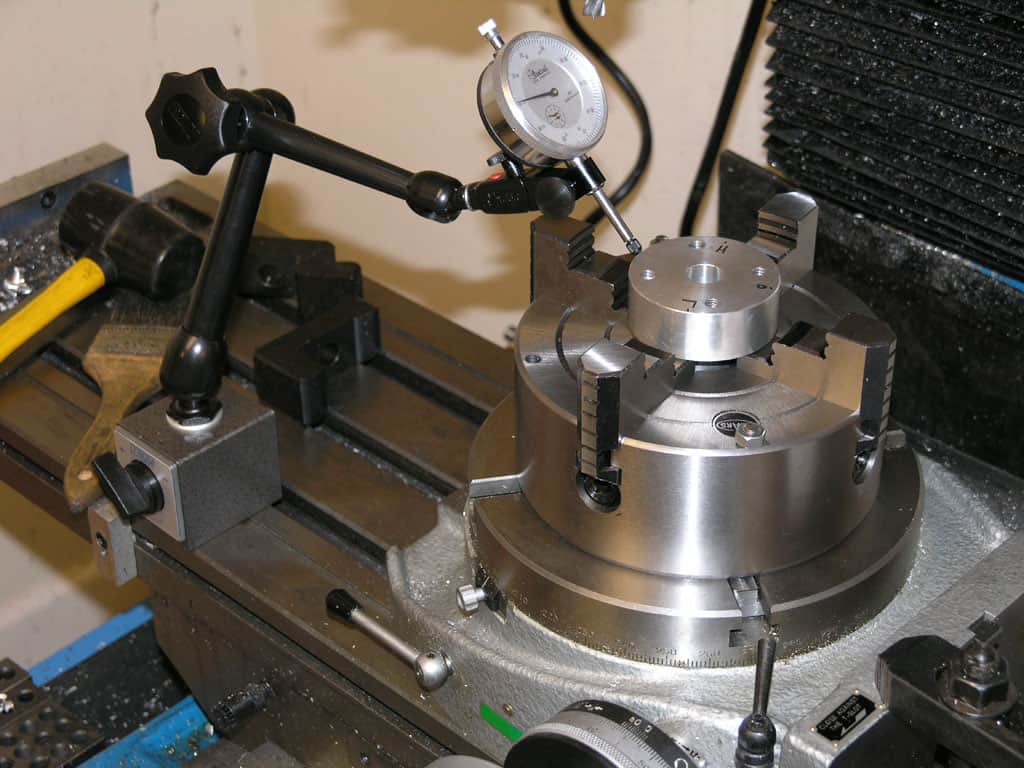
First, you want to make sure your part is properly centered on the table. To do that, I clamp the table down on the mill table (no special place is needed), put my Indicol indicator holder on the mill spindle, and find some round feature on the part to indicate on. For example, on the plate milling fixture above, indicate on the round boss, or on the center hole. Spin the table and bump the part in until spinning the table doesn’t move the indicator.
Second, locate the center of rotation directly under the mill spindle. You can simply use the X and Y table handwheels to do this. Use that Indicol to indicate off of a circular feature you want centered under the spindle. Turn the indicol around on the spindle and adjust the handwheels until the indicator stays put relative to the spindle position. A Blake Coaxial indicator will make this last even simpler.
When you’re rounding partially by cranking a part around on the rotary table, it’s really easy to go a little too far and screw things up. The answer is to drill the end points to make the exact stopping point on the rotab a lot less sensitive:
Centering with a Blake indicator is really fast, but what if you don’t have a Blake, or worse, what if your mill is too small to accomodate one? Here is a nice solution I found on a German site. This fellow has made an ER collect fixture for his rotary table, and has taken care that when installed on the table, the axis of the collet is aligned with the table’s axis. He can then place a dowel or other straight pin in the collet and line up until it will go into a similarly sized collet on the spindle. Nice trick! It’s similar to how Widgitmaster showed me to align a drill chuck on a QCTP to the lathe centerline with a dowel pin held in the lathe chuck.

rotary filing—that is, running a circular cutter withfile-like teeth in the headstock of alathe.Rotary filling and later,true milling were developed to reduce time and effort
The crosslide table all depends on where the slides are...above the point of rotation or below. Below is pretty much the cheap line and really is redundant putting on a mill as you already have 2 axis there. Now, slides above the pivot point allows you to position your part any where on table, center it above the pivot using the slides (U & V axis?) all with out tapping it about like a rotary table w/o slides. Also, you can then offset a part to center a desired radius elsewhere...example: you need to mill a 4" square hole with r.535 in corners. On a plain rotary table you would need to relocate the part for each corner...with topslides you use the U & V axis to position the center of R.535 over the pivot and turn the corner. This works for all kinds of stuff...milling angles off the X&Y that come tang to a rad, or even milling multiple circles or countours on a single pc w/o remounting and locating the pc. Think of 3 O-ring grooves on a hydraulic cover, or the snowman shape in a gearpump hsg. These can get confusing as now you have a manual machine with C,U,V,W,X,Y,&Z axis....wow.
The best has to be Advance 15X15. I know this unit cost $4500 15 years ago.Troyke made them also but I don"t know of others. Palmgren I thought made the bottom slide type. Alas, the 2axis CNC retros can outrun it and these are rapidly becoming dinosaurs.

I usually get a good many arguments started about rotary table setups. I worked in a large forge die shop, and I still do the setups the way we were shown in that shop. Probably 95% of the time you used a rotary table on a rotary head milling machine, so getting stuff on center was step #1.
The first thing to be pointed out is that the center hole and OD of the table aren"t necessarily on the axis of rotation. Easy to check, take the worm out of engagement and pull the table around by hand with an indicator zeroed on the center hole. Just like indicating a part in a four jaw.
If it is on center, that"s great. If not, you can eyeball your part on center and lightly clamp while you indicate it in by pulling the table around by hand and tapping it. If you don"t have a concentric hole or OD to use an indicator on, a center punch mark and a pump center can be used.
Once the part is on the center of the rotary tables axis, it"s a simple matter to center it under the machine spindle by locking the table and rotating the machine spindle and indicating like you would normally.
Here is what I like to use as a test indicator holder. It can allow you to indicate in something without removing the tool. They have several options for in spindle or spindle nose clamp styles. eBay does have some cheaper import version that work ok, but once you have use the Indicol quality, there is a big difference. You will need to buy the test indicator as a seperate item. There are a lot on the market. I have had my B&S(brown and Sharp) "Best Test" indicator for almost 30 years and one repair. Reasonably rugged and very reliable. Sticky indicators like some imports do you no good. If the needle pointer does not move, it is inviting a false sense of security.
The whole premise is to use the spindle bearings to sweep an indicator around the surface you wish to align it to. It is much easier in concert with a DRO, but dials will get you there too.
As long as you do not move the table, you could indicate the part in by knocking it around until it sets in the same location. You could also spin the table itself and knock the part around to find its true center on the rotation of the table bearings. Some of the cheaper import rotary tables may not have the spindle bore as reliably on center as what they will rotate on their shaft.
The same indicator setup can check for spindle tram also. This will need to be checked periodically anyways to verify the spindle is perpendicular to the table surface. If the head is tilted and you indicate in a feature. If the point that it is indicated in at changes in height, so to will the location of the features you intend to machine in relation to that reference. The longer the tool bit is away from the indicated origin, the further off location the new feature will be. Where this is seen is when the part is indicated in at one level, but the distance between the spindle and work needs more room for the tool. So when the table drops away, the point of origin in relation the spindle center (being at an angle) is out lost in space now. The new feature(s) can be found way off location even though the table was moved correctly during the setup. Best advice is to keep this in mind if the knee or head will be moved in a Z axis, always check the tram first. Especially after a crash, broken cutter or large unexpected force at the cutter.
The same holds true for vises parallel to an axis. For critical work, always check the solid jaw for axis alignment. If it is at an angle and a feature is indicated in on one end of the jaws, it might not be at the other end. More or less exponentially to the angle it is off over XX distance from the origin.
Main objective here is to use as much of the machines built in geometry to maintain pure geometry on the part as the machines is capable of. A test indicator is the best way to obtain this level of precision.
Lagun’s BM RT is a bed type mill with C-Axis rotation and equipped with a rotary table. With a compact and robust design, this milling machine is ideal for machining bulky workpieces on all 5 sides.
Lagun’s BM RT mill is built with a modular configuration, which means all models in this spectacular line have interchangeable slides, rams and columns. This design method endows each machine with enhanced rigidity, precision and ergonomic working comfort for the operator.
Additionally the sturdy, oversized mill bed comes with reinforced ribbing, fortifying its stability during heavy milling. The hardy table, measuring at 63” x 47” (1600mm x 1200mm), column, slide and ram systems have been studied and as a result designed with roller/shoes that exceed the manufacturing requirements. Designed to be as close to the column as possible, the mills ram placement ensures a sturdy column-slide-ram assembly. This results in a rigid and light slide for vertical movement. To correct any ram deflection during cross movement they come equipped with special wedges.
*Note: Interested in more bed type milling machines? Take a look at our BM-C and BM-BL bed mills. Or browse all machining centers offered by Lagun Engineering here.
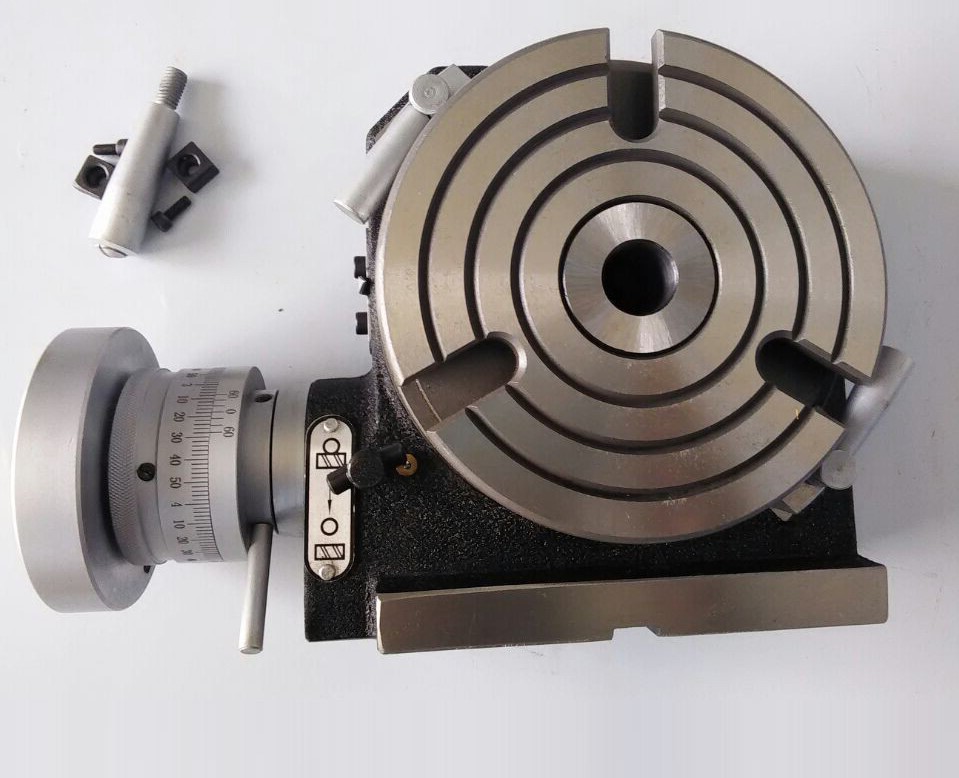
The reverse rotary table is perfect for using on the tilting angle table. The reverse mount allows access to the handwheel from the front of the machine (see photo below). If you used a standard rotary table in the previously described set-up, the handwheel would be mounted facing the backside of the X-axis.
NOTE: When the worm housing is reversed to the opposite side, a clockwise rotation of the handwheel or stepper motor will result in a counter-clockwise rotation of the rotary table.
The rotary tables can hold more weight when they are not under a continual load. Click on the Video tab above to see examples of different weights and uses for our rotary tables.

Rotary Tables└ Workholding Supplies└ Workholding & Toolholding└ CNC, Metalworking & Manufacturing└ Business & IndustrialAll CategoriesAntiquesArtBabyBooks & MagazinesBusiness & IndustrialCameras & PhotoCell Phones & AccessoriesClothing, Shoes & AccessoriesCoins & Paper MoneyCollectiblesComputers/Tablets & NetworkingConsumer ElectronicsCraftsDolls & BearsMovies & TVEntertainment MemorabiliaGift Cards & CouponsHealth & BeautyHome & GardenJewelry & WatchesMusicMusical Instruments & GearPet SuppliesPottery & GlassReal EstateSpecialty ServicesSporting GoodsSports Mem, Cards & Fan ShopStampsTickets & ExperiencesToys & HobbiesTravelVideo Games & ConsolesEverything Else

Whether you use mills, presses or lathes, machine tools are often only as useful as the accessories that come with them. Take care of repair tasks and add extra functionality with the machine tools accessories at Alibaba.com. If you need new milling machine rotary table or are seeking to replenish your component stocks, our wholesale store is the ideal place to look. We stock accessories for every type of machine tool, with multiple options in most cases. So add resilience to your operations and be ready for any production challenge with the machine tools accessories in our store.
Machine tools come in all shapes and sizes, and so do the accessories that make them tick. For instance, CNC and manual lathes can be customized with jaw chucks, shanks, woodworking knives, drill chucks, rotary chucks, clamps, and turning tools. Add brushes and sanding discs, and turn your machine tool into a multi-purpose machining center. Add a range of cutting tools to milling machines, pick the right drum sanders for your drills, or add a lathe dog to make turning much easier. There are accessories for hydraulic presses, add-ons like drag chains, and many other machine tools accessories. And if you need replacement milling machine rotary table, Alibaba has everything you need.
Our machine tools catalog is packed with accessories. Search the listings for your preferred tool and zero in on accessories that can enhance its functionality. From control handles to tool holders, thread holders and saw blades, the whole panorama of machine tools accessories is here and ready to order. There"s no better way to add extra stocks and renovate machinery when the time comes. When new milling machine rotary table are required, head to the Alibaba wholesale store and give your machinery a new lease of life.

Thanks to Martin Power and Robert from Kitagawa Europe, I have another guest blog. Robert looks at rotary tables and how the small manual rotary table you might have for your drill press or milling table compairs with it’s bigger brother in the industrial world. For the model engineer, the rotary table would be for cutting curved slots say for an expansion link or rounding the ends of con rods. In industry there is a much wider range of tasks for the rotary table.
Those of you that have converted your shed or garage into a workshop will probably already know what a rotary table is may even have installed one. Even if you haven’t got your own personal workshop; there is a good chance that you have at some time used or at least come into contact with a rotary table. This will most likely have occurred in the school environment when in a Design and Technology class – or similar subject. The rotary table is of course a clamping mechanism that is used in the shaping of metal parts or components, in conjunction with various machines, including lathes, drill presses and milling machines.
In its most basic operation a rotary table is used to hold the object piece firmly in position whilst holes are made in an evenly spaced fashion. The image above shows such a task being carried out on a rotary table which has been mounted on a drill press. There are however much more advanced rotary tables available on the market, which are used in various manufacturing industries.
The photo above shows Kitagawa’s popular GT200 model, which is ideal for heavy machining. The complexity, accuracy and performance levels of such machines make their shed based cousins look like mere toys.
The top end rotary tables are commonly used in the manufacture of components that are used in cars, trains, planes and boats. Every time you travel somewhere in a vehicle you will be making use of metal work that has been created by a rotary table. It is of course important that every component of a vehicle is made precisely to ensure the safety of those using it. In order to deliver this precision, computer numerically controlled (CNC) rotary tables are used in the manufacturing world.
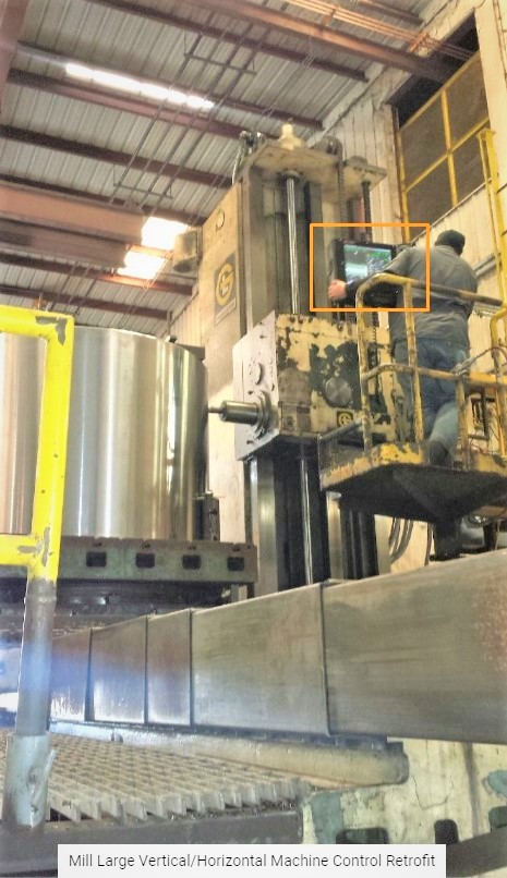
Rather than positioning and turning the rotary table manually; a CNC driven model operates using pre-programmed commands which are entered into a control module such as the one above. The rotary table is also able to communicate with the other end of the metalworking machine that holds the shaping tools. As a result both are able to work in unison; bringing precision and safety.
Whilst rotary tables play a key role in the manufacture of parts in the transport industry, it by no means the extent of their reach. Their usefulness stretches to many other areas of business, from construction to pipe laying. In order to fulfil their role in so many different environments it is important that rotary tables are both adaptable and available in various sizes and configurations.
In the example above we see a rotary table that has a huge through-hole capacity of 345mm. This allows long bar and tube shaped workpieces to be clamped effectively and is ideal for producing pipes to be used to move gas, water and oil. For such tasks, the standard three and four jawed chucks, such as the one below, are not suitable.
Such a clamping solution cannot deliver a suitable torque to hold the piece in place whilst it is being shaped. The result will be that shaping tools will deflect from their target, thus compromising the quality of the final component. Instead a collet chucks as shown below is more suitable for use when manufacturing pipes and bars.
The circular shape of the collet chuck allows pressure to be applied evenly to the outer surface of the workpiece. This allows larger gripping torque to be applied and also reduces the likelihood of surface damage to the workpiece that could otherwise be caused by standard jawed chucks. The clamping pressure is applied by tightening accompanying sleeve over the outside of the collet chuck.
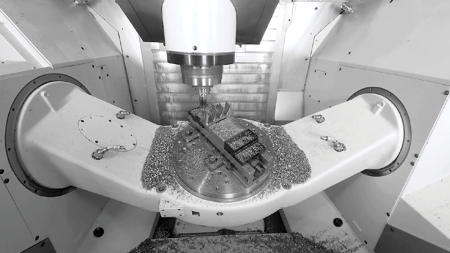
The final main difference between manufacturing rotary tables and those used in schools and hobby workshops centres on the ability to choose tilting options. Standard rotary tables allow for the workpiece to be positioned along 3 axis in relation to the shaping tool. In contrast many models used in manufacturing include a manual or CNC tilting device that enables the workpiece to be positioned on a 4th and 5th axis. The image below shows a rotary table with tilting capabilities being use alongside a drill press.
As you can see, the machining tool is now able to approach the workpiece from different angles than would otherwise be possible. This allows for more much complex items to be produced, such as flute shaped ones.

A cookie is a small text file that a website saves on your computer or mobile device when you visit the site. It enables the website to remember your actions and preferences (such as login, language, font size and other display preferences) over a period of time, so you don’t have to keep re-entering them whenever you come back to the site or browse from one page to another.
When using a rotary table on a Milling Machine, whether to mill an arc or drill holes in some circular pattern, there are two things that must be done to set up the workpiece. First, the workpiece must be centered on the rotary table. Second, the rotary table must be centered under the spindle. Then the mill table can be moved some appropriate distance and you can start cutting.
You could center the table under the spindle first, by indicating off the hole in the center of the table. Then you could mount the workpiece on the table and indicate off the workpiece. There are two problems with this approach. First, you are assuming that the hole in the table is true and centered. That may or may not be true. Second, this approach risks a sort of accumulation of errors, as you’re measuring from two different features (the rotary table’s hole and some feature on the workpiece). First center the workpiece on the rotary table, and then center the rotary table under the spindle.
To center the workpiece on the rotary table, spin the rotary table and watch for deflection of the indicator pointer. Adjust the position of the mill table(X and Y) as required, until the needle no longer deflects.
You dial in a rotary table by placing a dial test indicator in a chuck or collet in the spindle, which is then rotated by hand with the indicator tip in contact with the hole of the rotary table. If your machine can be taken out of gear, it helps to do so, so the spindle swings freely. It’s obviously easier to use a drill chuck than a collet, too, so you have something that you can turn easily. Make your adjustments using the saddle and table hand wheels.
Once you have center located (the indicator will read the same as you rotate the spindle, it’s a very good idea to set both of your dials at “0”, instead of marking some random location. Make sure you have backlash set properly, too. Set the dial is reading in a positive direction so it’s easy to count off any changes, and you never have to remember which way you had chosen to set backlash. I also always mark the table and saddle with a wax pencil so I know where center is located. That tells you when to stop turning the handle when “0” comes around if you want to get the table back to center to load another part.
Once you have located center of the table and have set dials and locked the table and saddle, you usually have some feature on your part that you desire to be centered. In some cases it may be a hole, in others it may be the outside edge of the circular part. In a case like either of these, it’s common practice to use the same indicator and swing it inside the hole or the perimeter of the part. The perimeter may require you to get around clamps, which can usually be accomplished by using the quill to move the indicator up far enough to clear them. When you dial in parts to a table that has already been located, you tap the part around, you do not make adjustments with the saddle or table handles. Tap the part after you’ve snugged up the clamps slightly, so it doesn’t move about wildly. You can achieve virtually perfect location that way, certainly as close as the machine is capable of working.
After the workpiece is centered on the rotary table, you now turn the spindle by hand, so the indicator tip sweeps the inside of the hole. Adjust the position of the mill table as required until no needle deflection is noted.


 8613371530291