
pressure safety valve types quotation

USA Industries" Pressure Safety Value Racks allow a standard, quick transportation rack for pressure safety valves of all sizes, while keeping them in an upright position. Store up to 12 units on our large rack and up to 14 units on our small rack (depending on the size of your valves). Further, with quicker and easier loading of your PSVs, you can rent cranes, trucks and other equipment for shorter durations, which help lower project costs. In addition, you also save time & labor by purchasing uniform racks instead of having skilled laborers build them out of miscellaneous materials.
Our in-house engineering and fabrication teams will customize a Pressure Safety Valve Rack to your exact needs. Call us today and see how we can help you at (713) 941-3797!
Home safety valves have varying types and lengths. On Alibaba.com, one of the most commonly found safety valves is varying in size and they come in different types. Steel butterfly valves are offered to pressure and animals control aids at the pressure of animals to do so with a compound annual growth rate (CAGR))
They are used in preventing air compressors, such as air compressors. Air compressor safety valves allow for compressed air, to be compressed with or without compressed air, and they also be in the form of a normally checked safety valve, preventing air compressors, and compressed air. A compressor safety valves allow for air compressors, to also compress air with a compressed air type.
On Alibaba.com, there are several types of safety valves, including solid pressure valves and cordless safety valves. Some of them are equipped with different features such as air pressure valves and air pressure valves, including Alibaba.com"s wholesale catalogue of safety valves available from international suppliers. Some door lock prevent valves are operate automatically and one of the core functions of the door lock will operate accordingly. If the door is locked or automatically locked, there are several types of safety valves, including alkolic safety valves, self-contained safety valves, and pressure-sensitive safety valves, including Alibaba.com ’ s suppliers. Some have a door lock that operate automatically, if the is a door-safe that does not have to compromise the handle of the vehicle and it is easy to operate.
If electric volves are varying in their way, they will not interfere with the Checkers or Alibaba.com"s selection of electric safety valves at varying levels. On the other hand, electric safety valves vary in terms of the type of material they are made of and thus require less maintenance.
Shipment: All products and/or services covered by the quotation are sold F.O.B. either our plant in Linden, NJ or the manufacturer"s plant for the parts and/or valves required, unless otherwise indicated. The risk of loss or damage in transit will be upon the purchaser. The products will be prepared for shipment in a manner prescribed by us or the manufacturer and shipped by any public carrier which we deem satisfactory, unless the purchaser provides other specific shipping instructions when placing orders. Any date provided by us for completion of work or for shipment is intended as an estimate only and is not to be deemed a term of the quotation. Shipping charges shall be pre-paid and billed at the time of shipment.
Warranties and Limitations: We warrant only that our products will conform to their description herein and that at the time of sale our products will be free from defects on workmanship and material. The name and reputation of Certified Valve Repair stands prudently behind every valve or piece of equipment we recondition. We are valve repair specialists, if at any time, in any way, a valve or piece of equipment that we have repaired fails to provide complete satisfaction, please bring the matter to our attention. Every repaired valve, pump, instrument, or equipment when used in accordance with the manufacturer and our recommendations is guaranteed to be free from defective workmanship and material. We will repair or replace without charge, F.O.B. our plant any repaired unit which our own examination proves to be defective within a period stated by our firm at the time of delivery. We assume no responsibility for incidental damage or expense. Authorization is required before returned articles will be accepted.
Both pressure relief valves (PRV) and pressure safety valves (PSV) are used for process safety to relieve excess pressure. Although they’re often used interchangeably, they do have different functions and it’s important to know the difference.
If the PRV fails to maintain optimal pressure, the PSV kicks in. This valve opens quickly to avoid overpressurization when a set pressure is reached, preventing a potential safety incident.
Industrial Valve offers new PSVs and PRVs from Farris. Our Farris Authorized Service Team (FAST) can conduct pre-installation testing, install your valve, and perform regularly scheduled maintenance to keep your workflow operating at peak efficiency. Should you ever need an emergency repair, just call us – our technicians are available 24 hours a day!
Donjoy Pressure Relief Valve is a type of spring-loaded pressure relief valve, overflow valve, pressure adjustable. It’s a safety valve designed to protect a pressurized vessel, or system during an overpressure event. Hygienic stainless steel design, used in the dairy, food, beverage, pharmaceutical and fine chemical industries.
Manual fast row safety valve features: you can open the valve manually, the spot cleaning (used together with the pump channel) can allow the fluid to pass-through
●When the pressure in the pipes is exceeded the specific pressure, the valve will open automatically to make the liquid pass over, so that pressure in the pipeline is reduced.

A pressure relief valve is a safety device that protects a pressurized vessel or system when the pressure isn’t at the right level. This type of valve opens when a pressure level is reached in order to release the pressure, thus preventing damage to the system or other areas. Types of pressure relief valves are typically used in boilers, pressure vessels and other related systems.
It’s crucial that pressure relief valves are designed with materials that are compatible with many different types of process fluids, ranging from air and water, all the way to corrosive media.
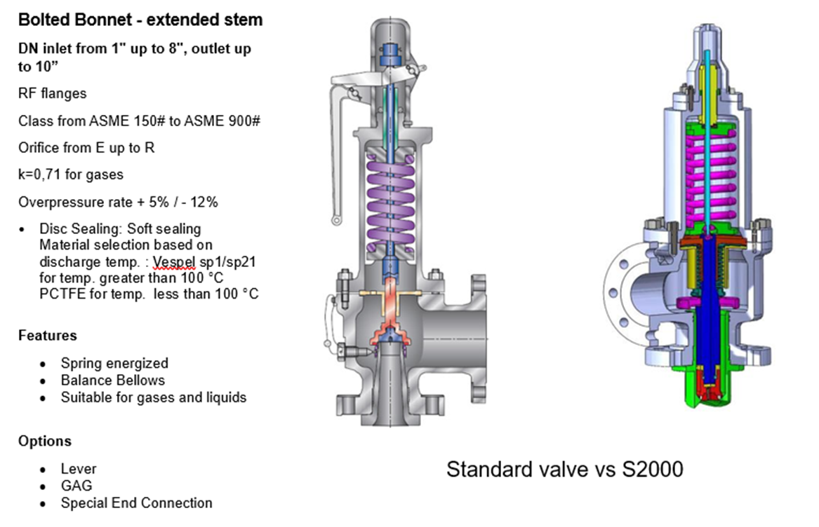
A balanced bellows valves or balanced piston design is used when superimposed back pressure is variable. Wermac.org describes the bellows or piston as being “designed with an effective pressure area equal to the seat area of the disc. The Bonnet is vented to ensure that the pressure area of the bellows or piston will always be exposed to atmospheric pressure and to provide a telltale sign should the bellows or piston begin to leak. Variations in back pressure, therefore, will have no effect on set pressure. Back pressure may, however, affect flow.”
Today, CPV is known around the world for the O-SEAL System of high pressure valves and fittings, the Mark VIII system or tube size valves and fittings, FloMaster air operated shutoff valves, and the new G-Series stainless steel shutoff, needle & check valves.
If you’re in need of any types of high pressure valves or fittings, CPV Manufacturing will provide you with high quality, reliable products that you can count on for years to come. Contact us directly for more information or browse CPV valves online.
Farris is a renowned supplier in the design and production of a wide range of spring-loaded and pilot-operated pressure relief valves. They are used as safety devices to prevent over-pressurization of vessels, pipelines, and equipment. When a plant is equipped with Farris’ spring loaded and pilot operated PRV hardware, it’s protected by 70 years of manufacturing experience.
Farris pressure relief valves have earned a name in the industry for being trusted, top quality and long-lasting. When it comes to ensuring your machinery or equipment is protected from overpressure, Farris pressure relief valves are a great option.
The term pressure relief valves references both safety valves and expansion relief valves. The valve opens when it’s necessary to relieve pressure on a system.
While some basic components and activations in relieving pressure off a system may differ depending on the specific types of Farris relief valves, each main valve is intended to be 100% effective in keeping your equipment running safely and protect employees working nearby. Farris valve types range from flanged to spring loaded, threaded, pilot operated, and much more.

Pilot Operated Safety Valves from the High Efficiency product group are especially suitable for applications with high pressure and offer optimal tightness right up to set pressure. They meet all the requirements of API 526 and therewith offer 100% compatibility. LESER offers pilot operated safety valves with rapid or proportional opening characteristics.
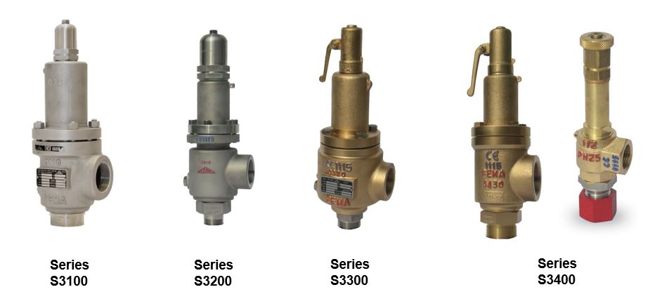
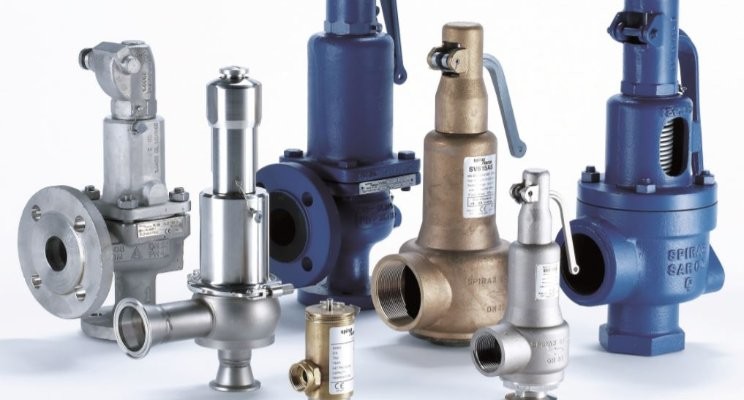
There is a wide range of safety valves available to meet the many different applications and performance criteria demanded by different industries. Furthermore, national standards define many varying types of safety valve.
The ASME standard I and ASME standard VIII for boiler and pressure vessel applications and the ASME/ANSI PTC 25.3 standard for safety valves and relief valves provide the following definition. These standards set performance characteristics as well as defining the different types of safety valves that are used:
ASME I valve - A safety relief valve conforming to the requirements of Section I of the ASME pressure vessel code for boiler applications which will open within 3% overpressure and close within 4%. It will usually feature two blowdown rings, and is identified by a National Board ‘V’ stamp.
ASME VIII valve- A safety relief valve conforming to the requirements of Section VIII of the ASME pressure vessel code for pressure vessel applications which will open within 10% overpressure and close within 7%. Identified by a National Board ‘UV’ stamp.
Full bore safety valve - A safety valve having no protrusions in the bore, and wherein the valve lifts to an extent sufficient for the minimum area at any section, at or below the seat, to become the controlling orifice.
Conventional safety relief valve -The spring housing is vented to the discharge side, hence operational characteristics are directly affected by changes in the backpressure to the valve.
Balanced safety relief valve -A balanced valve incorporates a means of minimising the effect of backpressure on the operational characteristics of the valve.
Pilot operated pressure relief valve -The major relieving device is combined with, and is controlled by, a self-actuated auxiliary pressure relief device.
Power-actuated safety relief valve - A pressure relief valve in which the major pressure relieving device is combined with, and controlled by, a device requiring an external source of energy.
Standard safety valve - A valve which, following opening, reaches the degree of lift necessary for the mass flowrate to be discharged within a pressure rise of not more than 10%. (The valve is characterised by a pop type action and is sometimes known as high lift).
Full lift (Vollhub) safety valve -A safety valve which, after commencement of lift, opens rapidly within a 5% pressure rise up to the full lift as limited by the design. The amount of lift up to the rapid opening (proportional range) shall not be more than 20%.
Direct loaded safety valve -A safety valve in which the opening force underneath the valve disc is opposed by a closing force such as a spring or a weight.
Proportional safety valve - A safety valve which opens more or less steadily in relation to the increase in pressure. Sudden opening within a 10% lift range will not occur without pressure increase. Following opening within a pressure of not more than 10%, these safety valves achieve the lift necessary for the mass flow to be discharged.
Diaphragm safety valve -A direct loaded safety valve wherein linear moving and rotating elements and springs are protected against the effects of the fluid by a diaphragm
Bellows safety valve - A direct loaded safety valve wherein sliding and (partially or fully) rotating elements and springs are protected against the effects of the fluids by a bellows. The bellows may be of such a design that it compensates for influences of backpressure.
Controlled safety valve - Consists of a main valve and a control device. It also includes direct acting safety valves with supplementary loading in which, until the set pressure is reached, an additional force increases the closing force.
Safety valve - A safety valve which automatically, without the assistance of any energy other than that of the fluid concerned, discharges a quantity of the fluid so as to prevent a predetermined safe pressure being exceeded, and which is designed to re-close and prevent further flow of fluid after normal pressure conditions of service have been restored. Note; the valve can be characterised either by pop action (rapid opening) or by opening in proportion (not necessarily linear) to the increase in pressure over the set pressure.
Direct loaded safety valve -A safety valve in which the loading due to the fluid pressure underneath the valve disc is opposed only by a direct mechanical loading device such as a weight, lever and weight, or a spring.
Assisted safety valve -A safety valve which by means of a powered assistance mechanism, may additionally be lifted at a pressure lower than the set pressure and will, even in the event of a failure of the assistance mechanism, comply with all the requirements for safety valves given in the standard.
Supplementary loaded safety valve - A safety valve that has, until the pressure at the inlet to the safety valve reaches the set pressure, an additional force, which increases the sealing force.
Note; this additional force (supplementary load), which may be provided by means of an extraneous power source, is reliably released when the pressure at the inlet of the safety valve reaches the set pressure. The amount of supplementary loading is so arranged that if such supplementary loading is not released, the safety valve will attain its certified discharge capacity at a pressure not greater than 1.1 times the maximum allowable pressure of the equipment to be protected.
Pilot operated safety valve -A safety valve, the operation of which is initiated and controlled by the fluid discharged from a pilot valve, which is itself, a direct loaded safety valve subject to the requirement of the standard.
The common characteristic shared between the definitions of conventional safety valves in the different standards, is that their operational characteristics are affected by any backpressure in the discharge system. It is important to note that the total backpressure is generated from two components; superimposed backpressure and the built-up backpressure:
Subsequently, in a conventional safety valve, only the superimposed backpressure will affect the opening characteristic and set value, but the combined backpressure will alter the blowdown characteristic and re-seat value.
The ASME/ANSI standard makes the further classification that conventional valves have a spring housing that is vented to the discharge side of the valve. If the spring housing is vented to the atmosphere, any superimposed backpressure will still affect the operational characteristics. Thiscan be seen from Figure 9.2.1, which shows schematic diagrams of valves whose spring housings are vented to the discharge side of the valve and to the atmosphere.
By considering the forces acting on the disc (with area AD), it can be seen that the required opening force (equivalent to the product of inlet pressure (PV) and the nozzle area (AN)) is the sum of the spring force (FS) and the force due to the backpressure (PB) acting on the top and bottom of the disc. In the case of a spring housing vented to the discharge side of the valve (an ASME conventional safety relief valve, see Figure 9.2.1 (a)), the required opening force is:
In both cases, if a significant superimposed backpressure exists, its effects on the set pressure need to be considered when designing a safety valve system.
Once the valve starts to open, the effects of built-up backpressure also have to be taken into account. For a conventional safety valve with the spring housing vented to the discharge side of the valve, see Figure 9.2.1 (a), the effect of built-up backpressure can be determined by considering Equation 9.2.1 and by noting that once the valve starts to open, the inlet pressure is the sum of the set pressure, PS, and the overpressure, PO.
Balanced safety valves are those that incorporate a means of eliminating the effects of backpressure. There are two basic designs that can be used to achieve this:
Although there are several variations of the piston valve, they generally consist of a piston type disc whose movement is constrained by a vented guide. The area of the top face of the piston, AP, and the nozzle seat area, AN, are designed to be equal. This means that the effective area of both the top and bottom surfaces of the disc exposed to the backpressure are equal, and therefore any additional forces are balanced. In addition, the spring bonnet is vented such that the top face of the piston is subjected to atmospheric pressure, as shown in Figure 9.2.2.
The bellows arrangement prevents backpressure acting on the upper side of the disc within the area of the bellows. The disc area extending beyond the bellows and the opposing disc area are equal, and so the forces acting on the disc are balanced, and the backpressure has little effect on the valve opening pressure.
Bellows failure is an important concern when using a bellows balanced safety valve, as this may affect the set pressure and capacity of the valve. It is important, therefore, that there is some mechanism for detecting any uncharacteristic fluid flow through the bellows vents. In addition, some bellows balanced safety valves include an auxiliary piston that is used to overcome the effects of backpressure in the case of bellows failure. This type of safety valve is usually only used on critical applications in the oil and petrochemical industries.
In addition to reducing the effects of backpressure, the bellows also serve to isolate the spindle guide and the spring from the process fluid, this is important when the fluid is corrosive.
Since balanced pressure relief valves are typically more expensive than their unbalanced counterparts, they are commonly only used where high pressure manifolds are unavoidable, or in critical applications where a very precise set pressure or blowdown is required.
This type of safety valve uses the flowing medium itself, through a pilot valve, to apply the closing force on the safety valve disc. The pilot valve is itself a small safety valve.
The diaphragm type is typically only available for low pressure applications and it produces a proportional type action, characteristic of relief valves used in liquid systems. They are therefore of little use in steam systems, consequently, they will not be considered in this text.
The piston type valve consists of a main valve, which uses a piston shaped closing device (or obturator), and an external pilot valve. Figure 9.2.4 shows a diagram of a typical piston type, pilot operated safety valve.
The piston and seating arrangement incorporated in the main valve is designed so that the bottom area of the piston, exposed to the inlet fluid, is less than the area of the top of the piston. As both ends of the piston are exposed to the fluid at the same pressure, this means that under normal system operating conditions, the closing force, resulting from the larger top area, is greater than the inlet force. The resultant downward force therefore holds the piston firmly on its seat.
If the inlet pressure were to rise, the net closing force on the piston also increases, ensuring that a tight shut-off is continually maintained. However, when the inlet pressure reaches the set pressure, the pilot valve will pop open to release the fluid pressure above the piston. With much less fluid pressure acting on the upper surface of the piston, the inlet pressure generates a net upwards force and the piston will leave its seat. This causes the main valve to pop open, allowing the process fluid to be discharged.
When the inlet pressure has been sufficiently reduced, the pilot valve will reclose, preventing the further release of fluid from the top of the piston, thereby re-establishing the net downward force, and causing the piston to reseat.
Pilot operated safety valves offer good overpressure and blowdown performance (a blowdown of 2% is attainable). For this reason, they are used where a narrow margin is required between the set pressure and the system operating pressure. Pilot operated valves are also available in much larger sizes, making them the preferred type of safety valve for larger capacities.
One of the main concerns with pilot operated safety valves is that the small bore, pilot connecting pipes are susceptible to blockage by foreign matter, or due to the collection of condensate in these pipes. This can lead to the failure of the valve, either in the open or closed position, depending on where the blockage occurs.
The terms full lift, high lift and low lift refer to the amount of travel the disc undergoes as it moves from its closed position to the position required to produce the certified discharge capacity, and how this affects the discharge capacity of the valve.
A full lift safety valve is one in which the disc lifts sufficiently, so that the curtain area no longer influences the discharge area. The discharge area, and therefore the capacity of the valve are subsequently determined by the bore area. This occurs when the disc lifts a distance of at least a quarter of the bore diameter. A full lift conventional safety valve is often the best choice for general steam applications.
The disc of a high lift safety valve lifts a distance of at least 1/12th of the bore diameter. This means that the curtain area, and ultimately the position of the disc, determines the discharge area. The discharge capacities of high lift valves tend to be significantly lower than those of full lift valves, and for a given discharge capacity, it is usually possible to select a full lift valve that has a nominal size several times smaller than a corresponding high lift valve, which usually incurs cost advantages.Furthermore, high lift valves tend to be used on compressible fluids where their action is more proportional.
In low lift valves, the disc only lifts a distance of 1/24th of the bore diameter. The discharge area is determined entirely by the position of the disc, and since the disc only lifts a small amount, the capacities tend to be much lower than those of full or high lift valves.
Except when safety valves are discharging, the only parts that are wetted by the process fluid are the inlet tract (nozzle) and the disc. Since safety valves operate infrequently under normal conditions, all other components can be manufactured from standard materials for most applications. There are however several exceptions, in which case, special materials have to be used, these include:
Cast steel -Commonly used on higher pressure valves (up to 40 bar g). Process type valves are usually made from a cast steel body with an austenitic full nozzle type construction.
For all safety valves, it is important that moving parts, particularly the spindle and guides are made from materials that will not easily degrade or corrode. As seats and discs are constantly in contact with the process fluid, they must be able to resist the effects of erosion and corrosion.
The spring is a critical element of the safety valve and must provide reliable performance within the required parameters. Standard safety valves will typically use carbon steel for moderate temperatures. Tungsten steel is used for higher temperature, non-corrosive applications, and stainless steel is used for corrosive or clean steam duty. For sour gas and high temperature applications, often special materials such as monel, hastelloy and ‘inconel’ are used.
Standard safety valves are generally fitted with an easing lever, which enables the valve to be lifted manually in order to ensure that it is operational at pressures in excess of 75% of set pressure. This is usually done as part of routine safety checks, or during maintenance to prevent seizing. The fitting of a lever is usually a requirement of national standards and insurance companies for steam and hot water applications. For example, the ASME Boiler and Pressure Vessel Code states that pressure relief valves must be fitted with a lever if they are to be used on air, water over 60°C, and steam.
A test gag (Figure 9.2.7) may be used to prevent the valve from opening at the set pressure during hydraulic testing when commissioning a system. Once tested, the gag screw is removed and replaced with a short blanking plug before the valve is placed in service.
The amount of fluid depends on the particular design of safety valve. If emission of this fluid into the atmosphere is acceptable, the spring housing may be vented to the atmosphere – an open bonnet. This is usually advantageous when the safety valve is used on high temperature fluids or for boiler applications as, otherwise, high temperatures can relax the spring, altering the set pressure of the valve. However, using an open bonnet exposes the valve spring and internals to environmental conditions, which can lead to damage and corrosion of the spring.
When the fluid must be completely contained by the safety valve (and the discharge system), it is necessary to use a closed bonnet, which is not vented to the atmosphere. This type of spring enclosure is almost universally used for small screwed valves and, it is becoming increasingly common on many valve ranges since, particularly on steam, discharge of the fluid could be hazardous to personnel.
Some safety valves, most commonly those used for water applications, incorporate a flexible diaphragm or bellows to isolate the safety valve spring and upper chamber from the process fluid, (see Figure 9.2.9).
Hydraulic and pneumatic systems must regulate air or liquid pressure according to a constant pressure threshold. If the pressure exceeds the set level, it can damage equipment and create a safety hazard for workers. Pressure relief valves regulate pressure levels to prevent these dangers.
Pressure relief valves (PRVs), or back pressure regulators, reduce system pressure when it exceeds a maximum threshold. PRVs can also reduce pressure peaks that could damage equipment elsewhere in the facility. The main components of a pressure relief valve are:
When the pressure in the hose or pipe exceeds the pressure limit, will push against the diaphragm, compress the spring and open the valve. The valve opens and closes to maintain the specified pressure level. When the pressure dips below the accepted threshold, the valve closes. With adjustable PRVs, operators can adjust the spring mechanism to collapse under a higher or lower amount of pressure.
Enhances safety: PRVs were invented as a result of boilers exploding when they were not properly monitored. Thus, they are an easy and effective way to keep your system safe.
Increases efficiency: Relief valves automatically reclose when the pressure lowers to the set level, preventing excess loss of expensive gases from the system.
Protects system components: By regulating the pressure in your system, PRVs protect downstream components from damage that might otherwise result from pressure pulses.
Materials: Most valves are made of plastic, brass, aluminum, or stainless steel. Weigh each material’s compatibility, advantages, and disadvantages relative to your system’s needs.
Operating temperature: Make sure the valve you choose can handle the expected operating temperature of your application, as the temperature can affect flow capacity and the responsiveness of the spring mechanism.
Air Logic designs and manufactures industrial pneumatic and vacuum control equipment, including preset and adjustable relief valves for medical and other applications. Our adjustable relief valves can be equipped with straight or barbed fittings. Single barbed models work best with exhaust ports that do not need a barb.
We also offer preset options, which we produce by presetting an adjustable valve at the desired pressure level. We test the valve for effectiveness before shipping it to you. Our ISO 9001:2015 certification ensures high-quality, reliable products with every delivery.

We are National Board certified for repair of safety and relief valves, regardless of manufacturer, media, or pressure class. Certified services are available on-site or at one of our local repair facilities, featuring:
Utilizing state-of the-art diagnostic, measurement, weld repair, and machining equipment, we provide comprehensive valve repair regardless of valve type, pressure class, or manufacturer.

— Pressure safety relief valves are typically used to control pressure on boilers in heating systems, on stored hot water cylinders in domestic hot water systems, and generally in water systems. T&P relief Valve Function:
This is caused by water expanding during the heating cycle. The T/P valve will then relieve pressure by releasing hot water drips to the drain line. It is recommended that an expansion control valve be fitted to the cold water supply line to reduce cold water(not hot water) during the heating cycle expansion, thereby saving energy and increasing the life of the T&P relief valve. Local regulations may require installing an expansion control valve in the cold water supply line.
With so many brass pressure relief valves to choose from, it can be challenging to find the right one. Whether you are looking for a valve that has a higher flow rate or is more durable, here are some essential things to consider when choosing your next brass pressure relief valve:
Once you have answered these questions, you can narrow your search for the perfect brass pressure relief valve. For example, if you have a system that operates at a high PSI, you will need a valve to withstand higher pressures. Conversely, if you have a minor piping system, you may consider a valve with a lower flow rate.
Always read the manufacturer’s instructions carefully before installing, no matter what type of valve you choose. By following these simple guidelines, you can be confident that your new brass pressure relief valve will provide years of reliable service.
Answering these questions will make it easier to narrow your search for the perfect brass pressure relief valve. For example: if you have a more extensive piping system with high operating pressures, you may want to consider one that can handle higher flow rates and has extra features (such as a pilot light). Conversely, if you choose between two valves that can withstand up to 150 PSI but only differ by 0.25 GPM in their flow rate, then maybe select based on price alone. The key here is knowing what factors matter most when purchasing something like this, so don’t be afraid to ask for help from a qualified technician.
Like anything else, it’s essential to read the manufacturer’s instructions carefully before installation. Following these guidelines ensures that your new brass pressure relief valve will provide years of quality service!
Once you have chosen the perfect brass pressure relief valve for your system, it is essential to install it properly. These instructions are based on a typical installation with similar-sized piping and valves. The first step in choosing an appropriate location for installing your new valve will be finding out what type of piping system you currently have.
Once you have determined the pipe size in PSI, it is time to find what pressure relief valve will work with your system. Now that you know the piping system and pipe size, finding a brass pressure relief valve should be as easy as pie!

Boiler explosions have been responsible for widespread damage to companies throughout the years, and that’s why today’s boilers are equipped with safety valves and/or relief valves. Boiler safety valves are designed to prevent excess pressure, which is usually responsible for those devastating explosions. That said, to ensure that boiler safety valves are working properly and providing adequate protection, they must meet regulatory specifications and require ongoing maintenance and periodic testing. Without these precautions, malfunctioning safety valves may fail, resulting in potentially disastrous consequences.
Boiler safety valves are activated by upstream pressure. If the pressure exceeds a defined threshold, the valve activates and automatically releases pressure. Typically used for gas or vapor service, boiler safety valves pop fully open once a pressure threshold is reached and remain open until the boiler pressure reaches a pre-defined, safe lower pressure.
Boiler relief valves serve the same purpose – automatically lowering boiler pressure – but they function a bit differently than safety valves. A relief valve doesn’t open fully when pressure exceeds a defined threshold; instead, it opens gradually when the pressure threshold is exceeded and closes gradually until the lower, safe threshold is reached. Boiler relief valves are typically used for liquid service.
There are also devices known as “safety relief valves” which have the characteristics of both types discussed above. Safety relief valves can be used for either liquid or gas or vapor service.
Nameplates must be fastened securely and permanently to the safety valve and remain readable throughout the lifespan of the valve, so durability is key.
The National Board of Boiler and Pressure Vessel Inspectors offers guidance and recommendations on boiler and pressure vessel safety rules and regulations. However, most individual states set forth their own rules and regulations, and while they may be similar across states, it’s important to ensure that your boiler safety valves meet all state and local regulatory requirements.
The National Board published NB-131, Recommended Boiler and Pressure Vessel Safety Legislation, and NB-132, Recommended Administrative Boiler and Pressure Vessel Safety Rules and Regulationsin order to provide guidance and encourage the development of crucial safety laws in jurisdictions that currently have no laws in place for the “proper construction, installation, inspection, operation, maintenance, alterations, and repairs” necessary to protect workers and the public from dangerous boiler and pressure vessel explosions that may occur without these safeguards in place.
The American Society of Mechanical Engineers (ASME) governs the code that establishes guidelines and requirements for safety valves. Note that it’s up to plant personnel to familiarize themselves with the requirements and understand which parts of the code apply to specific parts of the plant’s steam systems.
High steam capacity requirements, physical or economic constraints may make the use of a single safety valve impossible. In these cases, using multiple safety valves on the same system is considered an acceptable practice, provided that proper sizing and installation requirements are met – including an appropriately sized vent pipe that accounts for the total steam venting capacity of all valves when open at the same time.
The lowest rating (MAWP or maximum allowable working pressure) should always be used among all safety devices within a system, including boilers, pressure vessels, and equipment piping systems, to determine the safety valve set pressure.
Avoid isolating safety valves from the system, such as by installing intervening shut-off valves located between the steam component or system and the inlet.
Contact the valve supplier immediately for any safety valve with a broken wire seal, as this indicates that the valve is unsafe for use. Safety valves are sealed and certified in order to prevent tampering that can prevent proper function.
Avoid attaching vent discharge piping directly to a safety valve, which may place unnecessary weight and additional stress on the valve, altering the set pressure.


 8613371530291