
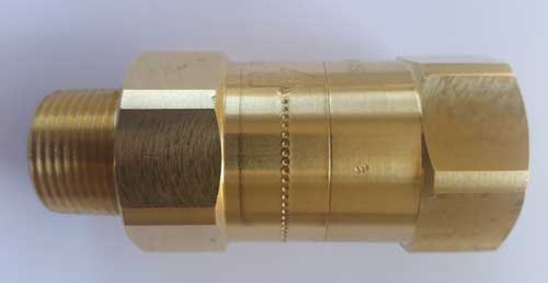
air safety valve free sample

Pressure relief valve is related to Microchek.com. We offer competitive pricing and reliability because we are the manufacture. Parts are molded and assembled in the U.S. The Microchek system incorporates this cartridge and a wide selection of end pieces to accommodate most connection requirements. The Microchek valve is a cartridge check valve incorporating an innovative guided poppet design. Relief valves are used to hold a fluid circuit or reservoir at a positive or negative pressure. We can select valves that fall into a specific cracking pressure range if needed. The Microchek valve has a low pressure drop and can be specified with a wide variety of cracking pressures.
The Microchek valve is a cartridge check valve incorporating an innovative guided poppet design. Relief valves are used to hold a fluid circuit or reservoir at a positive or negative pressure. We want the opportunity to help you solve your flow control applications and we can build special configurations.
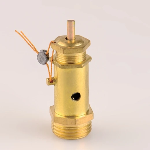
An OSHA COMPRESSED AIR SAFETY SHUT-OFF VALVES should be placed immediately after the air control shut off valve and before the hose on a compressor, and after each discharge port that a hose is connected to.
Before starting the compressor the air control valve should be closed completely. When the compressor unloads, open the air shut off control valve very slowly. Full port ball valves tend to work better than gate or butterfly type valves.
The air shut off control valve must be fully open for the OSHA COMPRESSED AIR SAFETY SHUT-OFF VALVES to work. Some portable air compressor manufacturers recommend start-up with the air control valve slightly open. In this case you may have to close the valve and reopen it slowly to the full open position, or wait for the safety shut-off valve to reset itself.
If the OSHA COMPRESSED AIR SAFETY SHUT-OFF VALVES fails to operate despite meeting all condi-tions, check the hose line for obstructions or a hose mender restricting normal air flow.
• Turn on air supply slowly (to avoid tripping OSHA safety valve). Prior to fully reaching operation conditions, the OSHA COMPRESSED AIR SAFETY SHUT-OFF VALVES should suddenly activate and stop air flow.
• If the OSHA COMPRESSED AIR SAFETY SHUT-OFF VALVE is not activated the unit should be disconnected and the lower flow range OSHA COMPRESSED AIR SAFETY SHUT-OFF VALVES should be used. This means you need to use a different valve with a lower scfm range.
• At temperatures below 40°F ensure that OSHA COMPRESSED AIR SAFETY SHUT-OFF VALVES are not subject to icy conditions which may prevent proper functioning.

We take great pride in supplying valves and tube fittings for automobile industry,Textile,Molds, electric power and other industries, and exports to the countries like United States, Japan, Europe etc. Please be aware that our production lead times depend on specific items and quantities. Our success has been based on our understanding of the demands. That"s Why we always ensure that every order requirements are met.
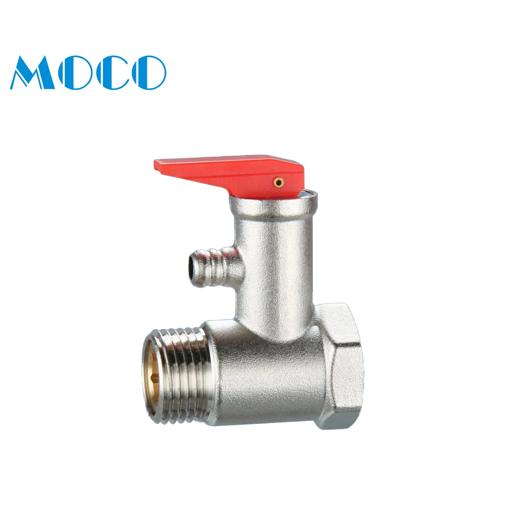
3) For this type of relief valve , we can setting the pressure grade before sales , we can setting 5kg pressure or 8 kg pressure according to your needed .
3) For this type of relief valve , we can setting the pressure grade before sales , we can setting 5kg pressure or 8 kg pressure according to your needed .
3) For this type of relief valve , we can setting the pressure grade before sales , we can setting 5kg pressure or 8 kg pressure according to your needed .
For final order . we can do air transfer and sea shipping . our factory are close to airport and seaport . usually transfer 1-5 ton goods to port cost 200 $ .
In addition to our cooper parts mainly used in pneumaic and hydraulic fidlds , we have developed pu air tubes ,samll ball valves,quick couplings,ect.RIXIN BRASS FITTING CO.,LTD founded in 1991 . The factory is a private enterprise covering the complete process of design , manufacture,marketing and service.

We take great pride in supplying valves and tube fittings for automobile industry,Textile,Molds, electric power and other industries, and exports to the countries like United States, Japan, Europe etc. Please be aware that our production lead times depend on specific items and quantities. Our success has been based on our understanding of the demands. That"s Why we always ensure that every order requirements are met.
3) For this type of relief valve , we can setting the pressure grade before sales , we can setting 5kg pressure or 8 kg pressure according to your needed .
3) For this type of relief valve , we can setting the pressure grade before sales , we can setting 5kg pressure or 8 kg pressure according to your needed .
3) For this type of relief valve , we can setting the pressure grade before sales , we can setting 5kg pressure or 8 kg pressure according to your needed .
For final order . we can do air transfer and sea shipping . our factory are close to airport and seaport . usually transfer 1-5 ton goods to port cost 200 $ .
In addition to our cooper parts mainly used in pneumaic and hydraulic fidlds , we have developed pu air tubes ,samll ball valves,quick couplings,ect.RIXIN BRASS FITTING CO.,LTD founded in 1991 . The factory is a private enterprise covering the complete process of design , manufacture,marketing and service.

Two hands safety valve, which allows a safety use of two hands pneumatic controls (for example two push-button 3/2 N.C. to a certain distance) excluding false signals ...
... -start valve with Series MX2 air treatment units without the need for additional connection interfaces. The soft-start valve is positioned upstream of the safety valves, ...
The S50 Safety Shut Off valve is mainly used to avoid any damage to components as well as to avoid too high or too low pressure in the gas train. This could cause high financial losses and/or injured ...
The S100 Safety Shut Off valve is mainly used to avoid any damage to components as well as to avoid too high or too low pressure in the gas train. This could cause high financial losses and/or injured ...
The main purpose of the safety relief valve SL 5 is to relieve small pressure increases and quantities in the controlled system to prevent the safety shut-off valve from ...
Material: Body- CF8M; Valve Seat- CF8M Métal Seat, PTFE Soft Seat available Orifice Size: fc"(15mm), 3/4M(20mm), l"(25mm), l1/4,’(32mm)I ltë”(40mm), ...
PVS type slam shut valves are pilot-operated relief valves in which the opening and the closing of the main plug is controlled by a pilot device which is very ...
130 Series Safety valves are also available as Relief valves. Relief valves, identified by the letter R after the type number, are devices with an operational function, ...
Cryogenic Safety Valves Type 06011 is made with stainless steel. It is provided as a safety device for protection against thermal expansion in pipework and parts of facilities. ...

Our Sanitary Air Relief Valve is designed to remove air from the line without loss of product, and will not allow air to enter the line or container under vacuum. The valve consists of a standard ferrule, a double seated chamber containing a polypropylene ball, and a vent tube. All held together with two heavy duty clamps.
The Air Relief Valve aids in bleeding the line removing air pockets that may form during operation. Similarly, mounting this valve before a pump will relieve any air pockets that may cause air binding.
A safety valve must always be sized and able to vent any source of steam so that the pressure within the protected apparatus cannot exceed the maximum allowable accumulated pressure (MAAP). This not only means that the valve has to be positioned correctly, but that it is also correctly set. The safety valve must then also be sized correctly, enabling it to pass the required amount of steam at the required pressure under all possible fault conditions.
Once the type of safety valve has been established, along with its set pressure and its position in the system, it is necessary to calculate the required discharge capacity of the valve. Once this is known, the required orifice area and nominal size can be determined using the manufacturer’s specifications.
In order to establish the maximum capacity required, the potential flow through all the relevant branches, upstream of the valve, need to be considered.
In applications where there is more than one possible flow path, the sizing of the safety valve becomes more complicated, as there may be a number of alternative methods of determining its size. Where more than one potential flow path exists, the following alternatives should be considered:
This choice is determined by the risk of two or more devices failing simultaneously. If there is the slightest chance that this may occur, the valve must be sized to allow the combined flows of the failed devices to be discharged. However, where the risk is negligible, cost advantages may dictate that the valve should only be sized on the highest fault flow. The choice of method ultimately lies with the company responsible for insuring the plant.
For example, consider the pressure vessel and automatic pump-trap (APT) system as shown in Figure 9.4.1. The unlikely situation is that both the APT and pressure reducing valve (PRV ‘A’) could fail simultaneously. The discharge capacity of safety valve ‘A’ would either be the fault load of the largest PRV, or alternatively, the combined fault load of both the APT and PRV ‘A’.
This document recommends that where multiple flow paths exist, any relevant safety valve should, at all times, be sized on the possibility that relevant upstream pressure control valves may fail simultaneously.
The supply pressure of this system (Figure 9.4.2) is limited by an upstream safety valve with a set pressure of 11.6 bar g. The fault flow through the PRV can be determined using the steam mass flow equation (Equation 3.21.2):
Once the fault load has been determined, it is usually sufficient to size the safety valve using the manufacturer’s capacity charts. A typical example of a capacity chart is shown in Figure 9.4.3. By knowing the required set pressure and discharge capacity, it is possible to select a suitable nominal size. In this example, the set pressure is 4 bar g and the fault flow is 953 kg/h. A DN32/50 safety valve is required with a capacity of 1 284 kg/h.
Coefficients of discharge are specific to any particular safety valve range and will be approved by the manufacturer. If the valve is independently approved, it is given a ‘certified coefficient of discharge’.
This figure is often derated by further multiplying it by a safety factor 0.9, to give a derated coefficient of discharge. Derated coefficient of discharge is termed Kdr= Kd x 0.9
Critical and sub-critical flow - the flow of gas or vapour through an orifice, such as the flow area of a safety valve, increases as the downstream pressure is decreased. This holds true until the critical pressure is reached, and critical flow is achieved. At this point, any further decrease in the downstream pressure will not result in any further increase in flow.
A relationship (called the critical pressure ratio) exists between the critical pressure and the actual relieving pressure, and, for gases flowing through safety valves, is shown by Equation 9.4.2.
Overpressure - Before sizing, the design overpressure of the valve must be established. It is not permitted to calculate the capacity of the valve at a lower overpressure than that at which the coefficient of discharge was established. It is however, permitted to use a higher overpressure (see Table 9.2.1, Module 9.2, for typical overpressure values). For DIN type full lift (Vollhub) valves, the design lift must be achieved at 5% overpressure, but for sizing purposes, an overpressure value of 10% may be used.
For liquid applications, the overpressure is 10% according to AD-Merkblatt A2, DIN 3320, TRD 421 and ASME, but for non-certified ASME valves, it is quite common for a figure of 25% to be used.
Two-phase flow - When sizing safety valves for boiling liquids (e.g. hot water) consideration must be given to vaporisation (flashing) during discharge. It is assumed that the medium is in liquid state when the safety valve is closed and that, when the safety valve opens, part of the liquid vaporises due to the drop in pressure through the safety valve. The resulting flow is referred to as two-phase flow.
The required flow area has to be calculated for the liquid and vapour components of the discharged fluid. The sum of these two areas is then used to select the appropriate orifice size from the chosen valve range. (see Example 9.4.3)

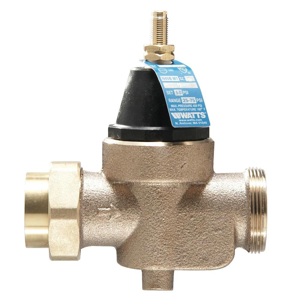
Hydraulic and pneumatic systems must regulate air or liquid pressure according to a constant pressure threshold. If the pressure exceeds the set level, it can damage equipment and create a safety hazard for workers. Pressure relief valves regulate pressure levels to prevent these dangers.
Pressure relief valves (PRVs), or back pressure regulators, reduce system pressure when it exceeds a maximum threshold. PRVs can also reduce pressure peaks that could damage equipment elsewhere in the facility. The main components of a pressure relief valve are:
When the pressure in the hose or pipe exceeds the pressure limit, will push against the diaphragm, compress the spring and open the valve. The valve opens and closes to maintain the specified pressure level. When the pressure dips below the accepted threshold, the valve closes. With adjustable PRVs, operators can adjust the spring mechanism to collapse under a higher or lower amount of pressure.
Enhances safety: PRVs were invented as a result of boilers exploding when they were not properly monitored. Thus, they are an easy and effective way to keep your system safe.
Increases efficiency: Relief valves automatically reclose when the pressure lowers to the set level, preventing excess loss of expensive gases from the system.
Materials: Most valves are made of plastic, brass, aluminum, or stainless steel. Weigh each material’s compatibility, advantages, and disadvantages relative to your system’s needs.
Operating temperature: Make sure the valve you choose can handle the expected operating temperature of your application, as the temperature can affect flow capacity and the responsiveness of the spring mechanism.
Air Logic designs and manufactures industrial pneumatic and vacuum control equipment, including preset and adjustable relief valves for medical and other applications. Our adjustable relief valves can be equipped with straight or barbed fittings. Single barbed models work best with exhaust ports that do not need a barb.
We also offer preset options, which we produce by presetting an adjustable valve at the desired pressure level. We test the valve for effectiveness before shipping it to you. Our ISO 9001:2015 certification ensures high-quality, reliable products with every delivery.
As one of the leading manufacturers of cavity free plug valves and special valves, AZ supplies to production plants in the chemical, petrochemical, pharmaceutical, paper, food industries as well as for nuclear power plants and many other areas. Special valves for highest demands in areas with high operating pressures and aggressive, toxic or abrasive media are designed and developed together with our customers. In the 50 years of the company’s existence, AZ has continuously developed to meet the increasing requirements of customers active around the world and today AZ manufactures internationally on four continents.

Besides the P/T value of the sleeve the limitations of the valve bodies also have to be considered. Please refer to the EN 12516-1 resp. ASME B16.34 in order to choose a proper pressure rating (PN/class). The shown values refer to austenitic stainless steel 1.4408 (A351 Gr. CF8M).

The primary purpose of a safety valve is to protect life, property and the environment. Safety valves are designed to open and release excess pressure from vessels or equipment and then close again.
The function of safety valves differs depending on the load or main type of the valve. The main types of safety valves are spring-loaded, weight-loaded and controlled safety valves.
Regardless of the type or load, safety valves are set to a specific set pressure at which the medium is discharged in a controlled manner, thus preventing overpressure of the equipment. In dependence of several parameters such as the contained medium, the set pressure is individual for each safety application.

The primary purpose of a pressure relief valve is to protect life, property and the environment. Pressure relief valves are designed to open and release excess pressure from vessels or equipment and then close again.
The function of pressure relief valves differs depending on the main type or loading principle of the valve. The main types of pressure relief valves are spring-loaded, weight-loaded and controlled pressure relief valves.
Regardless of the type or load, pressure relief valves are set to a specific set pressure at which the medium is discharged in a controlled manner, thus preventing overpressure of the equipment. In dependence of several parameters such as the contained medium, the set pressure is individual for each safety application.
Safety valves and pressure relief valves are crucial for one main reason: safety. This means safety for the plant and equipment as well as safety for plant personnel and the surrounding environment.
Safety valves and pressure relief valves protect vessels, piping systems, and equipment from overpressure, which, if unchecked, can not only damage a system but potentially cause an explosion. Because these valves play such an important role, it’s absolutely essential that the right valve is used every time.
The valve size must correspond to the size of the inlet and discharge piping. The National Board specifies that the both the inlet piping and the discharge piping connected to the valve must be at least as large as the inlet/discharge opening on the valve itself.
The connection types are also important. For example, is the connection male or female? Flanged? All of these factors help determine which valve to use.
The set pressure of the valve must not exceed the maximum allowable working pressure (MAWP) of the boiler or other vessel. What this means is that the valve must open at or below the MAWP of the equipment. In turn, the MAWP of the equipment should be at least 10% greater than the highest expected operating pressure under normal circumstances.
Temperature affects the volume and viscosity of the gas or liquid flowing through the system. Temperature also helps determine the ideal material of construction for the valve. For example, steel valves can handle higher operating temperatures than valves made of either bronze or iron. Both the operating and the relieving temperature must be taken into account.
Back pressure, which may be constant or variable, is pressure on the outlet side of the pressure relief valve as a result of the pressure in the discharge system. It can affect the set pressure of the upstream valve and cause it to pop open repeatedly, which can damage the valve.
For installations with variable back pressure, valves should be selected so that the back pressure doesn’t exceed 10% of the valve set pressure. For installations with high levels of constant back pressure, a bellows-sealed valve or pilot-operated valve may be required.
Different types of service (steam, air, gas, etc.) require different valves. In addition, the valve material of construction needs to be appropriate for the service. For example, valves made of stainless steel are preferable for corrosive media.
Safety valves and relief valves must be able to relieve pressure at a certain capacity. The required capacity is determined by several factors including the geometry of the valve, the temperature of the media, and the relief discharge area.
These are just the basic factors that must be considered when selecting and sizing safety valves and relief valves. You must also consider the physical dimensions of the equipment and the plant, as well as other factors related to the environment in which the valve will operate.
![]()
Valves for industrial applicationsIn order to prevent the uncontrolled rise in pressure in pressure vessels or pressurized pipelines, a safety valve is inserted. The safety valve is designed so that it opens at a given maximum pressure, thereby relieving the line or the container. Safety valves find their use in almost all areas of the pressure vessel and pipeline construction. In cryogenics as a spring-loaded safety valve for example.


 8613371530291