
testing gas safety valve quotation

Searching for tools to control the flow of your piping system? Explore one of the largest featured collections of products and discover a range of wholesale gas safety valve price on Alibaba.com. When you search for gas safety valve price and related items, you will be able to find many types of gas safety valve price varying in size, shape, use, and quality, all at prices in which are highly reasonable!
There are many uses of valves - mainly controlling the flow of fluids and pressure. Some examples include regulating water for irrigation, industrial uses for controlling processes, and residential piping systems. Magnetic valves like those using the solenoid, are often used in a range of industrial processes. Whereas backflow preventers are often used in residential and commercial buildings to ensure the safety and hygiene of the water supplies. Whether you are designing a regulation system for irrigation or merely looking for a new replacement, you will be able to find whatever type of gas safety valve price that you need. Our products vary from check valves to pressure reducing valves, ball valves, butterfly valves, thermostatic mixing valves, and a lot more.

With our FieldLab PSV/PRV Testing software and hardware, it is possible to conduct the test and record most of the information on testing a Pressure Safety Valve (PSV) or Proportional Relief Valve (PRV) directly on the calibrator. After the test is completed the data is then transferred electronically to a PC where a test report with graphs, customer data, tag data and other required information can be output and shared.
The unique PSV/PRV test mode captures the PSV crack and reseats pressure by logging pressure at 200 times per second. Most competitors" devices do not reliably capture the crack and reseat because the logging rate is too slow. The PSV/PRV mode also allows the user to select from standards such as ASME Boiler Code Section 8, simple crack tests or conditional crack tests where the allowable error may depend on the pressure of the PSV. The user can enter the pressure of the valve at the time of test and type in any other important information right on the FieldLab. Thus when the user returns to the office they can download all important information and create the certificates without a lot of extra effort.
IVI is a VR certified safety valve repair facility, approved by the National Board of Boiler and Pressure Vessel Inspectors as a VR certificate holder (stamp 179). We certify pressure relief valves in the shop and in the field for sections V and UV. We also perform on-site testing (while the plant operates) providing documented reports for all valves tested. We are also certified to administer special process conversions regarding machining, welding, heat treating, and N.D.T. (non-destructive testing) with our VR certificate.
With our VR stamp, we repair all types of pressure relief valves such as Consolidated, Crosby, Kunkle, Farris, Spence, Anderson Greenwood, and numerous other O.E.M. safety and pressure relief valves.
Ensure compliance, prevent overpressure and protect downstream equipment with industry regulated repairs for Section I & Section VIII Pressure and Safety Relief Valves. We offer rapid response and delivery times to minimize plant downtime while maximizing valve performance. We service all major makes and manufacturers for emergency, maintenance and scheduled outage needs. We also repair and replace conservation, tank and vacuum vents. Contact our sales team today to receive a quotation to repair, test or replace your safety relief valves.
Valsource is certified by The National Board of Boiler and Pressure Vessel Inspectors to repair and test Section I and Section VIII Pressure relief and Safety Relief Valves. Every valve is repaired to standards set by The National Board’s VR program. We provide 24/7 repair, testing and engineering services. We also maintain an extensive inventory and can provide replacement valves and parts with same day delivery options.
Valsource provides 24/7 repair and testing services in our shop or in the field. Our valve program allows our technicians to repair, remove, install and test your pressure relief and safety relief valves on-site. Using our AVK Electronic Test Vessel Package, our technicians are able to accurately test safety relief valves on-site without removing them from line. The primary function is to verify the set pressure in-line without having to shut down a system or unit. This service is a sure way to guarantee minimal downtime and peak valve performance. If you are preparing to service your boiler, Valsource technicians will come to your site and test each main steam safety valve to determine which valves require service. We will perform the repairs in-house or on-site using our 53’ field machining trailer, install and re-test back to calibrated set points.
If you need the best in valve repair and remanufacturing, Valsource can deliver the right options for your company. We offer rapid response times and emergency repair services available to resolve unplanned outages quickly. Our experienced technicians look forward to working with you to determine the most effective solutions for your valve repair needs.

Media flow hydraulic processes and procedures are heavily dependent upon quality valves. Failure in a piping system from faulty valves can incur considerable and costly damage. In some cases, these failures may risk catastrophic property damage or injury and death to workers.
Because of the critical role valves have in complex and intricate processes, proper inspecting and routine testing should be part of a risk mitigation plan. Today, we’ll go over the kinds of valves, industry standards, and testing you might encounter.
While the function of a valve is relatively simple, the designs are diverse and sometimes complex. Below is a list of valves you may already be familiar with along with their applications.Butterfly Valve – A quarter-turn valve used to control the flow of liquid, gas, or particulate matter. It is used in treatment plants, food industry, ship industry, petrochemical plants, fire extinguisher systems, paper manufacturing, and many more applications.
Ball Valve – A shutoff valve with a rotary ball controls flow and pressure control in gas distribution systems as well as pressure reduction in connection with gas storage. It is used in applications involving corrosive fluids, slurries, or normal liquid and gases. Applications are found in the oil and natural gas industry, manufacturing sectors, chemical storage, some residential uses, etc.
Globe Valve – A linear motion valve used to start, stop, and regulate flow. It may be used for isolation and throttling. Applications include cooling water systems, fuel oil systems, feedwater or chemical feed systems, turbine lube oil, boiler, and main steam vents or drains.
Check Valve – A one-way, non-return valve where the flow runs freely in a single direction and works to prevent backflow. It is used in pumps, fluid systems (for chemical and power plants), and more.
Needle Valve – A plunger valve with a small opening (or port) that has a needle-shaped plunger that allows precise regulation of flow. It’s ideal for systems with lighter and less viscous media with low flow rates or systems with small channels and pipes. This valve regulates gas or water through an appliance or system.
Gate Valve – A sluice valve that is multi-turn and works by inserting a rectangular gate or wedge in the path of a flowing media. A threaded stem connects the actuator (such as a handwheel or motor) to the gate’s stem. It is found in industrial applications such as pharmaceuticals, manufacturing, automotive, oil and gas industry, or marine. It’s also useful in underground applications and is ideal for vertically-oriented setups (as it is space-saving).
Pinch Valve – A full bore or fully ported valve that “pinches” to obstruct the flow of fluids. It’s used for liquid, solid, and slurry applications. It’s ideal for isolating or regulating media that is abrasive, corrosive, and fibrous.
Plug Valve – A quarter-turn rotary motion valve where a tapered or cylindrical plug is used to start and stop the flow of media. Applications include natural gas piping systems, oil piping systems, coal slurries, mineral ores, mud, sewage, or vacuum to high-pressure applications.
Pressure Relief Valve – A safety relief valve designed to open at a preset pressure level and discharge fluid until an acceptable level of pressure is reached. It is necessary for applications where pressure levels are critical (such as oil and gas, petrochemical, or power generation using steam, air, gas, or liquid). Applications include firefighting, high-rise building systems, water towers or tanks, drinking water systems, or multi-phase applications in refinery and chemical processing systems.
Smooth and safe operations of industrial processes and equipment rely on control valves that perform with precision. The quality of production is optimal when valves most effectively regulate process variables such as temperature, pressure, and flow.
Testing valves to monitor performance promotes both product quality and (most importantly) safety. Valve failure has been to blame for several plant or refinery explosions. We follow set protocols and industry standards to ensure safety.
Globally-sourced products are on the rise, yet domestic manufacturing has scaled back, so every part of the valve supply chain sees a need for more testing.
Set standards achieve two aims: puts in place criteria that the valve is expected to meet or exceed and establishes testing procedures. This ensures the integrity of the valves and that the valve is fit to do its job within a process. Reliability and longevity are vital to these operations and testing allows us to make adjustments and repairs where necessary.
For the oil and gas industry standards, there is the American Petroleum Institute, and for general applications, there is the American National Standards Association. Below are some specific testing procedures found in various industries.
The API 598 covers the testing criteria of various types of valves (soft & metal seated). This valve inspection covers, examination, pressure, and leakage rates for metal-seated and resilient seated valves (including a butterfly valve test). In order for a valve to pass the test, there must be zero leakage
This standard applies to the testing and performance evaluation of the straightway, soft-seated quarter-turn valves when the valves are exposed to fire conditions.
This international standard testing applies to ball valves, check valves, plug valves, and API6D design pipeline check/gate valves. It specifies those requirements and provides recommendations for the design, manufacturing, testing, and documentation of these valves. This test is associated with Petroleum and Natural Gas Industries-Pipeline Transportation Systems-Pipeline Valves
This testing is for valves, gauges, and other safety fittings involved with boilers (including its piping installations). Specifications apply to the associated valves, mountings, and fittings.
To give you an idea of what testing is applied to determine the efficacy and the health of valves in industrial applications, we’ll go over those evaluation measures.
The valve is checked for leaks by having it partially open and subject to hydrostatic pressure at 50% higher than the rated working pressure. A specified amount of pressure is applied during this test. There are also specific water temperatures in effect (41°F to 122°F). In order to pass the test, there must not be any leaking from the valve. When valve material includes stainless steel, chloride ion content must be less than 100 ppm.
This test has the valve completely closed with the inlet subject to the hydrostatic pressure with the valve body filled with the testing fluid at a certain temperature.
The outlet side of the valve is monitored for any leaks. Pressure cannot be lower than the 110% maximum allowable pressure at 100 °F. The duration of applied pressure is usually one minute. For the valve to pass the test, it cannot leak from the stem and packing. A minimal amount of leakage from the sealing surface of the disc and seat is acceptable.
For this test, the valve is fully opened while the valve ends are closed. Pressure cannot be lower than the 110% maximum allowable pressure at 100 °F.
The testing duration lasts 15 seconds for a valve that’s less than 2 inches and for valves more than 2 inches, it lasts 60 seconds. During this process, the packing gland is closely inspected while it is under the backseat test pressure. It passes if there are no leaks from the valve or from the packing gland.
Industry standards and testing procedures in place offer the necessary guidance to maintain safe and optimally-performing operations. For each valve in your process, you should have routine testing as part of your standard operating procedure.
BVC is here to help you find the best valves for your operations and answer any questions you have about performance and safety considerations. For added quality assurance, we also offer a valve inspection certificate. Contact us today by phone, email, or contact form for assistance with your quality valve needs.
We also offer our “ANSI” shop, repairing and selling rebuilt pumps, ball valves, orbits and gate valves. Our on-site service utilizes four mobile units and one emergency unit.
We also recognize the importance of safety and training. The Mercer Valve Repair Division has an extensive training program to ensure that only qualified technicians are working on our customer’s valves.
Mercer Valve began its valve repair business in 1986, under the direction of Wesley L. Taylor. We became “VR” certified in 1986. In the fall of 1989, Glen Quillin became the Valve Repair Manager where he brought fifteen years of oil and gas industry experience to Mercer’s team. Since then, the Repair Division has grown from a two-man shop to 21 employees.
Safety is of the utmost importance when dealing with pressure relief valves. The valve is designed to limit system pressure, and it is critical that they remain in working order to prevent an explosion. Explosions have caused far too much damage in companies over the years, and though pressurized tanks and vessels are equipped with pressure relief vales to enhance safety, they can fail and result in disaster.
That’s also why knowing the correct way to test the valves is important. Ongoing maintenance and periodic testing of pressurized tanks and vessels and their pressure relief valves keeps them in working order and keep employees and their work environments safe. Pressure relief valves must be in good condition in order to automatically lower tank and vessel pressure; working valves open slowly when the pressure gets high enough to exceed the pressure threshold and then closes slowly until the unit reaches the low, safe threshold. To ensure the pressure relief valve is in good working condition, employees must follow best practices for testing them including:
If you consider testing pressure relief valves a maintenance task, you’ll be more likely to carry out regular testing and ensure the safety of your organization and the longevity of your
It’s important to note, however, that the American Society of Mechanical Engineers (ASME) and National Board Inspection Code (NBIC), as well as state and local jurisdictions, may set requirements for testing frequency. Companies are responsible for checking with these organizations to become familiar with the testing requirements. Consider the following NBIC recommendations on the frequency for testing relief valves:
High-pressure steam boilers 400 psi and greater – pressure test to verify nameplate set pressure every three years or as determined by operating experience as verified by testing history
High-temperature hot water boilers (greater than 160 psi and/or 250 degrees Fahrenheit) – pressure test annually to verify nameplate set pressure. For safety reasons, removal and testing on a test bench is recommended
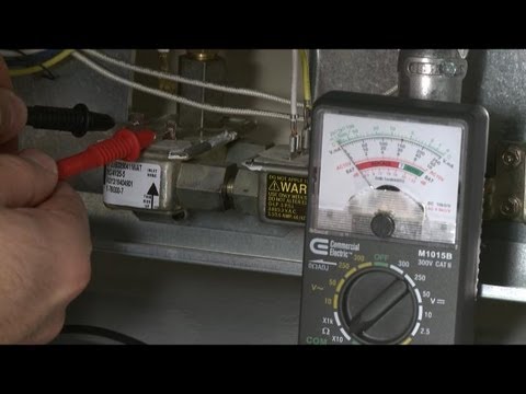
When testing the pressure relief valve, raise and lower the test lever several times. The lever will come away from the brass stem and allow hot water to come out of the end of the drainpipe. The water should flow through the pipe, and then you should turn down the pressure to stop the leak, replace the lever, and then increase the pressure.
One of the most common problems you can address with regular testing is the buildup of mineral salt, rust, and corrosion. When buildup occurs, the valve will become non-operational; the result can be an explosion. Regular testing helps you discover these issues sooner so you can combat them and keep your boiler and valve functioning properly. If no water flows through the pipe, or if there is a trickle instead of a rush of water, look for debris that is preventing the valve from seating properly. You may be able to operate the test lever a few times to correct the issue. You will need to replace the valve if this test fails.
When testing relief valves, keep in mind that they have two basic functions. First, they will pop off when the pressure exceeds its safety threshold. The valve will pop off and open to exhaust the excess pressure until the tank’s pressure decreases to reach the set minimum pressure. After this blowdown process occurs, the valve should reset and automatically close. One important testing safety measure is to use a pressure indicator with a full-scale range higher than the pop-off pressure.
Thus, you need to be aware of the pop-off pressure point of whatever tank or vessel you test. You always should remain within the pressure limits of the test stand and ensure the test stand is assembled properly and proof pressure tested. Then, take steps to ensure the escaping pressure from the valve is directed away from the operator and that everyone involved in the test uses safety shields and wears safety eye protection.
After discharge – Because pressure relief valves are designed to open automatically to relieve pressure in your system and then close, they may be able to open and close multiple times during normal operation and testing. However, when a valve opens, debris may get into the valve seat and prevent the valve from closing properly. After discharge, check the valve for leakage. If the leakage exceeds the original settings, you need to repair the valve.
According to local jurisdictional requirements – Regulations are in place for various locations and industries that stipulate how long valves may operate before needing to be repair or replaced. State inspectors may require valves to be disassembled, inspected, repaired, and tested every five years, for instance. If you have smaller valves and applications, you can test the valve by lifting the test lever. However, you should do this approximately once a year. It’s important to note that ASME UG136A Section 3 requires valves to have a minimum of 75% operating pressure versus the set pressure of the valve for hand lifting to be performed for these types of tests.
Depending on their service and application– The service and application of a valve affect its lifespan. Valves used for clean service like steam typically last at least 20 years if they are not operated too close to the set point and are part of a preventive maintenance program. Conversely, valves used for services such as acid service, those that are operated too close to the set point, and those exposed to dirt or debris need to be replaced more often.
Pressure relief valves serve a critical role in protecting organizations and employees from explosions. Knowing how and when to test and repair or replace them is essential.

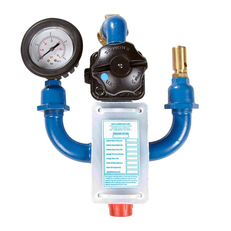
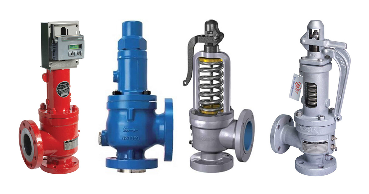
WITT is a manufacturer of Pressure relief valvesor Safety relief valves for technical gases. They are designed to protect against overpressure by discharging pressurized gases and vapors from pipelines, pressure vessels and plant components. Safety relief valves (SRV) are often the last line of defense against explosion – and such an explosion could be fatal. Other common names for safety relief valves are pressure relief valve (PRV), safety valve, pressure safety valve, overpressure valve, relief valve or blow-off valve.
WITT safety valves are very precise. They are individually preset to open at a predetermined pressure within the range 0.07 to 652 Psi. Their small size and orientation-independent installation allow a wide range of connection options. WITT relief valves also stand out due to their high blow-off flow rates of up to 970m³/h. They can be used within a temperature range of -76° F to +518°F and even with very low pressures.
For maximum safety, WITT undertakes 100 % testing of each safety relief valve before it is delivered. In addition, WITT offers individual testing of eachsafety valveby the TÜV, with their certificate as proof of the correct set pressure.
WITTsafety relief valvesare direct-acting, spring-loaded valves. When the preset opening pressure is reached, a spring-loaded element in the valve gives way and opens, and the pressure is relieved. Once the pressures are equalized, the valve closes automatically and can be reactivated any time the pressure rises again. Depending on the application and the nature of the gas, the safety relief valvescan either discharge to atmosphere, or via a connected blow-off line. The opening pressure of the safety valves is preset by WITT at the factory according to the customer’s requirements.
Safety relief valvesare used in numerous industries and industrial applications where, for example, gases pass through pipelines or where special process vessels have to be filled with gas at a certain pressure.
For most industrial applications using technical gases, brass is usually the standard material of construction of thesafety relief valvebody/housing. For the use of pressure relief valves with aggressive and corrosive gases, the housings are made of high-quality stainless steel (1.4541/AISI 321, 1.4404/AISI 316L, 1.4305/AISI 303 or 1.4571/AISI 316Ti). The use of aluminium as a housing material is also possible.
Depending on the type of gas used and individual customer requirements, various sealing materials and elastomers are available to ensure the safety of your systems under even the most difficult conditions.
WITT pressure relief valves are available with different connections. In addition to the standard versions with the usual internal or external threads, special versions with KF or CF flanges, VCR or UNF threads can also be ordered. Special adapters for connecting the safety relief valve to a blow-off line are also available.

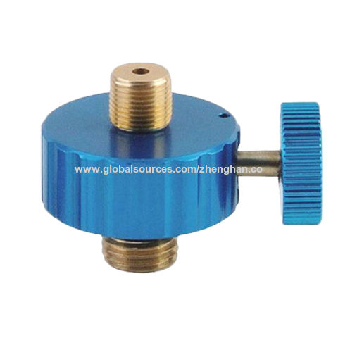
If you have been searching for a safety release valve that you can use to reduce short-term pressure surges successfully and diminish the effects of gas leaks, this is the product for ...
... regulators have safety valves which will slam shut in the event of emergencies, such as the gas reaching too high a pressure level. The valve works to protect any fittings ...
This product has hydraulically actuated class A gas safety valves to EN 161 used for automatic shut-off. It shuts off when unstimulated for gas and air, ...
The S 104 Safety Shut Off valve is mainly used to avoid any damage to components as well as to avoid too high or too low pressure in the gas train. This could cause high financial losses ...
The S50 Safety Shut Off valve is mainly used to avoid any damage to components as well as to avoid too high or too low pressure in the gas train. This could cause high financial losses ...
The S100 Safety Shut Off valve is mainly used to avoid any damage to components as well as to avoid too high or too low pressure in the gas train. This could cause high financial losses ...
... Pressure Safety Valve + Rupture Disk is protected and may be utilized autonomously as essential security gadgets or in conjunction. There are 3 possible combinations. The first combinations ...
It"s a Safety valve in according with Directives ATEX 20K/34/EU. Technical Norm Fire Prevention 41/256 31/10/2019. d.P.R. 10/520 19/03/1955 and subsequent amendments.
130 Series Safety valves are also available as Relief valves. Relief valves, identified by the letter R after the type number, are devices with an operational function, ...
V651 Series safety relief valves are produced as safety and relief type. Safety valves are pressure relief elements used to evacuate excessive pressure ...
PVS type slam shut valves are pilot-operated relief valves in which the opening and the closing of the main plug is controlled by a pilot device which is very ...
This range of spring loaded conventional and balanced safety relief valves is specifically designed for overpressure protection of unfired pressure vessel (ASME Section VIII application). ...
The EMERSON BM7 SERIES is a disk slam-shut valve characterized as automatic isolating elements, which are suitable for installation as safety devices in regulating stations. This device has a high operation ...
... control and regulate the gas, air flow to burners and other combustion devices. HMV is a unique safety valve that can be supplied for the requiremen of handling higher ...
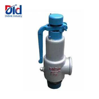
Type 50 is a safety valve for universal use. It can be used for nearly any industrial application, e.g. in shipping and pipeline construction, the chemical and petrochemical industries, ...
The RIEGER Safety valve Type SH prevents excessive pressure in steam and gaseous media in plant components and tanks. The set pressure is generally higher than the operating pressure of the system.
... sewage, gas, glycol, diathermic oil, industrial water, steam and other natural and aggressive media, depending on theresistance of materials usedfor the construction ofthe valve.
The realization of safe and smooth operations of industrial processes is heavily reliant on valves performing their function with precision. Thus, valve testing ensures that these valves meet design specifications for the duration of their operational life.
Generally, valve testing simulates operating conditions in a controlled environment to ensure fit for service valves. However, testing also occurs periodically after installation in line with standard practices.
There are several types of testing to which a valve could undergo. The required test depends on the application, manufacturer standards, and customer specifications. The following sections examine common tests, an overview of their procedure, and industry guidelines.
This test involves filling a valve body with a testing fluid, which is usually water with a corrosion inhibitor. Then, technicians apply pressure over a specific period of time. The time and level of pressure varies depending on factors including the valve material, valve size, and category of pressure test. But in most cases, the pressure level is higher than the operational/working pressure of the valve. Also, the procedure for the pressure test varies depending on the type of valve in question. Generally, pressure tests aim to ascertain the integrity of the valve shell, seat, and seal against leakages due to pressure. After carrying out a test, a valve will not be accepted if the following occurs:
Common industry guidelines for pressure testing valves can be found in ASME B16.34, API 598, MSS-SP-61, API 527, and ISO 5208. Many tests are recorded on paper wheel charts or manually, although digital options are becoming more prevalent.
Although water (hydrostatic) is the most common test medium in pressure testing, some conditions require pneumatic pressure testing of valves. For pneumatic testing, air or an inert gas such as nitrogen are the preferred media. Generally, in industry, hydrostatic testing is ideal for high-pressure applications where the equipment is not moisture sensitive.
In situations where moisture can damage certain equipment – usually via corrosion – or alter the chemical balance in the system, pneumatic testing is recommended. Also, industry guidelines recommend the use of pneumatic testing for cryogenic and low temperature valves. This is because it is difficult to remove all water after the test. The presence of moisture in an operating system is highly discouraged. The table below highlights more of the differences between hydrostatic and pneumatic testing in line with standards and industry practices.
Typically, the system is pressurized to at least1.5 times above the maximum operating pressure for shell testing, and 1.10 times for seat testing.Because it is used mostly for low-pressure applications, the system is usually pressurized to 10% above the maximum operating value or 100 psi max.
Requires extensive post-test clean-up to avoid damage to components or disruption to the system when operation begins.There is little or no need for clean-up after testing.
The process is straight-forward and poses less danger. Thus, semi-skilled personnel can oversee it.Because of the dangers involved, an experienced operator supervises this process. For example, nitrogen leakage can gradually displace the air in the test lab and affect personnel. Also, the effects of overpressure are more catastrophic.Hydraulic Testing vs. Pneumatic Testing
When pressure testing a valve, there are key components that are given a closer look for the duration of the process. Three of these include the shell, seal, and seat.
The valve shell refers to the main body of the device. Moreover, its testing in the industry is driven mostly by guidelines from API 598 and ASME B16.34. Typically, the valve is mounted on a test bench and partially opened. Then, the shell is pressurized, with ASME B16.34 recommending a minimum of 1.5 times the valve pressure rating at 100 ℉ (38 ℃) for hydrostatic testing. While that of pneumatic seat testing is 1.1 times the maximum allowable pressure. Pneumatic testing is done to 80-100 psi. Also, both the API and ASME standards recommend varying test duration depending on the size of the valve being tested. The table below summarizes the test duration.
In addition, the test water temperature should range between 41 ℉ (5 ℃) and 122 ℉ (50 ℃). And the pressure gauge used for measurements should have calibration ranging from not less than 1.5 times the test pressure, to not more than 4 times the test pressure. For a valve shell to pass the test, there shall be no visible leakage for the duration of the test.
A valve stem seal (packing) is also monitored during the shell test. For adjustable stem seals, the occurrence of leakage during the test is NOT a cause for rejection, as long as the manufacturer can demonstrate the seal’s capacity to retain at least the maximum allowable pressure of the valve without any visible leakage. Adjustments to the packing are allowed to eliminate leakage. For non-adjustable stem seals, no leakage is permitted during the shell test.
Typically, the valve seat test is carried out after testing the valve shell. With the same API and ASME standards as with the shell test providing guidance. The recommended pressure is 110% of the maximum allowable pressure at 100 ℉ (38 ℃), and the test time varies with size in accordance with ASME B16.34.
For valve sizes greater than 14 inches, the hydrostatic test leakage rate should not exceed two drops per minute per inch. While the pneumatic test leakage rate should be less than four bubbles per minute per inch.
One of the requirements of industrial valves is having reliable fire protection. This holds particularly true for sensitive applications such as oil and gas, refinery, and petrochemical industries. Moreover, valves in these industries must guarantee a reliable and safe shut-off in case of a fire incident.
In a fire test, a valve is pressurized and subject to high-temperature flames between 1382 ℉ (750 ℃) and 1832 ℉ (1000 ℃) for a period of thirty minutes. During this period, the heat intensity and the leakages – both internal and external – are monitored and measured. Also, after extinguishing the flames and allowing the valve to cool, the technician test its pressure-retaining capacity. All through the test, the leakage levels should be within acceptable limits for the valve to pass as being “fire-safe”. Some key things to note about fire testing include:
Technicians measure temperature measurement from at least two places. One is 1” (25 mm) from the upper stem packing box on the horizontal centerline, while the other measurement point is 1” below the valve.
Standards such as API 607, API 6FA, ISO 10497, BS 5146, and BS 6755 constitute industry guidelines for fire testing. On the basis of these guidelines, several companies set up their bespoke procedure for fire-safety valves. Of all the fire testing guidelines, API 607 and API 6FA are the most widely used. API 607 provides testing criteria for valves with non-metallic seating and quarter-turn valves. API 6FA provides the testing criteria for metal seated valves.
A fugitive emissions test aims to assess the impact of gas or vapor leakage from a valve. Although this leakage can be from anywhere along the piping system, statistics show that approximately 60% of fugitive emissions stem from valves. This data highlights the importance of this test. In addition, the impact of these emissions has significant consequences including:
When carrying out fugitive emission tests, the most common test gases are helium and methane. The valve is pressurized with the test gas at varying temperatures. Then technicians monitor for leakages via the sniffing or vacuum method. International standards such as API 622, API 624, API 644, ISO 15848-1, and ISO 15848-2 all provide guidance on how to carry out this valve test. However, most organizations develop their specifications to ensure application suitability.
Cryogenic testing of valves is done for those operating at low temperatures or in cryogenic service. The test procedure involves placing the valve within an insulated tank, with liquid nitrogen at temperatures of down to -320 ℉ (-196 ℃).
Then, helium pressurizes the valve to the operating pressure specified for its class. During the test, technicians closely monitor the temperature inside the valve and leakages. In the end, the valve is depressurized and warmed up until it attains ambient temperature. Thereafter, a detailed report summarizes the performance of the valve and whether leakages were within acceptable limits. There are several international standards that provide guidelines for cryogenic valve testing including ISO 28921-1, ISO 28921-2, EN 12567, and BS 6364.
In addition to the standards mentioned in the previous section, there are a host of standards that provide recommendations for different valve types and test procedures. The table below provides a list of these standards and the areas of testing they cover, for quick referencing.
API 598Valve inspection and test. Testing of cast iron gate, plug, check, and globe valves. Also, testing of steel gate, globe, check, ball, and butterfly valves. Cryogenic valves.
Keeping the flow of oil and gas in pipelines is a monumental task and requires several reliable pieces of equipment. Gas valves are one of these crucial components. Without gas valves, the oil and gas industry could not ensure that crude oil, refined gas, natural gas, and other materials get to their destination. Learn the basics of valves, including seven common types used within the oil and gas industry, to better understand what is required for the smooth and safe flow of materials.
A gas valve is a device used to regulate the flow of oil and gas. Opening or closing an aperture controls the amount of liquids and gases allowed through pipes. The valve controls the flow of fluids by stopping and starting, adjusting the amounts, controlling the direction, regulating pressure, or relieving pressure.
No two environments are the same. Some are highly corrosive. At the same time, others function under constant high pressure. Because of these variants, many different types of valves have been developed over the decades. Each type of valve has its own advantages and disadvantages. Successful operation and application require understanding the different types and uses within the gas and oil industry.
There are several types of gas valves because of the different environments in which they are used. Below is a breakdown of seven kinds commonly used in the oil and gas industry.
The gate valve may be the most commonly used in the industry. It uses a gate system to open or close a pipeline entirely. This is an excellent choice if the flow rate needs to be controlled and maintained. When the actuator completely opens the valve, the channel is unobstructed, allowing even slurry fluids like crude oil to flow easier. While it is not an ideal candidate if throttling is required in an application, there is not a noticeable pressure drop when this valve is used.
When pressure control is necessary, the globe valve is frequently chosen. It is also often used for open and close operations. The valve plug sits vertically raised and lowered by the actuator as needed. They tend to create a more significant pressure drop than other valve types because of the S-shaped passageway within them. They are a good choice for flow regulation and throttling functions.
Gas refineries find check valves extremely helpful as the device opens under pressure and does not allow backflow of fluid or material. Because of the restricted backflow, cross-contamination of the product is prevented. That is, different materials can use the same pipeline. There is no need for an actuator as required in other valve types. However, it does need precise installation to ensure the response to fluid pressure occurs as required.
The plug valve comprises a plug-shaped disc with a horizontal passageway bored through it. When the linear valve is open, fluid will move through the hole. Turning the actuator 90 degrees from the open position blocks any flow through the pipeline. This valve is not suggested for throttling functions but is ideal for unrefined oil products as found in biogas production.
Ball valves are rotary valves that give pipelines fast shut-offs where tight sealing is often required. They are best suited for operation under fully open or fully closed positions as they do not offer reasonable regulation control or throttle functions. This type of valve comes in many different styles, which provides options within the industry. For example, a floating ball valve works better in low-to-medium pressure pipelines, and trunnion ball valves can handle high-pressure conditions. These are easy to repair, offer solid sealing, and provide quick shut-offs.
These valves are simple in their construction, are lightweight, and compact. They use a disc-type element held by a rod to regulate flow. They can handle high-pressure pipelines and allow easy flow of materials. When they are closed, they shut tightly. Often, these are used in pipes with large diameters and where a gate valve is not applicable.
These valves provide additional safety of equipment either upstream or downstream from them. This type of valve may be found immediately before a regulator and is designed to remain open until a significant pressure change is detected. It then immediately shuts off the flow and must be reopened manually. They are sometimes referred to as relief and safety valves and are vital to the oil and gas industry in avoiding accidents and injury.
Because gas valves come in many different types and provide various functionalities, choosing the best one may be challenging. It is helpful to consider the primary function under which it will be used. Does the environment involve much pressure? Is there a need for additional safety measures provided by a slam-shut valve? Can the actuator be automated, or does it require only manual movement?
Additionally, consider the type of environment where the valve will need to function. By asking questions and taking the working environment into account, it is feasible to determine the best valve for the process at hand. The answers will indicate the type of materials best suited for the function.
For more than 30 years, Norgas Controls has provided the Canadian gas industry with quality valves, including slam-shut valves, gas shut-off ball valves, and gas plug valves. Contact us anytime for more information about our gas valves or any other product we carry. Our team is friendly and knowledgeable, standing ready to answer your questions and help obtain the best equipment for your project.

Established in the year .... in Padi, Behind Saravana Store, Chennai, Tamil Nadu, We “Power Tech Testing And Services” are an acknowledged organization and are Proprietorship based firm, engaged as a Manufacturer of Sand Vibro Feeder, Roller Conveyor, Dust Collector and many more. Apart from this we also provide Fabrication Service, Valve Testing Service, Maintenance Service, Etc.

Low voltage, oven safety valve with female wire terminals for a flat ignitor. This gas oven safety valve ensures that no gas is released until the igniter has received the proper voltage needed to ignite the gas range.
3/8" Oven safety valve with male wire terminals for a flat ignitor. This gas oven safety valve ensures that no gas is released until the igniter has received the proper voltage needed to ignite the gas range.
3/8" inlet Oven safety valve. This gas oven safety valve ensures that no gas is released until the igniter has received the proper voltage needed to ignite the gas range.
Dual terminal Oven safety valve. This gas oven safety valve ensures that no gas is released until the igniter has received the proper voltage needed to ignite the gas range.


 8613371530291