
subsurface safety valve free sample
Surface-controlled subsurface safety valves (SCSSVs) are critical components of well completions, preventing uncontrolled flow in the case of catastrophic damage to wellhead equipment. Fail-safe closure must be certain to ensure proper security of the well. However, this is not the only function in which it must be reliable—the valve must remain open to produce the well. Schlumberger surface controlled subsurface safety valves exceed all ISO 10432 and API Spec 14A requirements for pressure integrity, leakage acceptance criteria, and slam closure.
Through decades of innovation and experience, Schlumberger safety valve flapper systems are proven robust and reliable. The multizone dynamic seal technology for hydraulic actuation of subsurface safety valves is a further improvement in reliability performance when compared with traditional seal systems in the industry.
The multizone seal technology is currently available in the GeoGuard high-performance deepwater safety valves, which is validated to API Spec 14A V1 and V1-H.
The internal equalizing system contributes to the long-term performance of these valves, which are also designed to reduce problems associated with solids and scale deposition. The design has been rigorously tested with sand slurry to ensure operational longevity, whatever the well conditions.

This invention relates to surface controlled subsurface safety valves used in the oil and gas industry and particularly including a mechanism for temporarily locking the valves open and for remedial cycling of the valves.
It is common practice to complete oil and gas producing wells with systems including a subsurface safety valve controlled from the well surface to shut off fluid flow in the well tubing string. Generally such a valve is controlled in response to control fluid pressure conducted to the valve from a remote location at the well surface via a small diameter conduit permitting the well to be selectively shut in as well conditions require. However, the present invention is not limited to use with safety valves that respond only to fluid pressure signals. The surface controller is typically equipped to respond to emergency conditions such as fire, broken flow lines, oil spills, etc. Frequently it is necessary to conduct well servicing operations through a subsurface safety valve. When a safety valve malfunctions, it may be necessary to install a second safety valve. In any event, it may be desirable to either permanently or temporarily lock the safety valve open. For example, if the well servicing operation requires extending a wireline tool string through the subsurface safety valve, it is preferable to use a lock open system which is not dependent upon control fluid pressure from the well surface. When operations are being carried out through an open subsurface safety valve such as pressure and temperature testing, it can be extremely expensive and time-consuming for a valve to accidentally close on the supporting wireline causing damage to the wireline and sensing apparatus supported therefrom. Additional well servicing procedures are required to retrieve the damaged equipment. Subsurface safety valves including both a permanent and a temporary lock open mechanism are shown in the following U.S. Pat. Nos. 3,786,865; 3,882,935; 4,344,602; 4,356,867; and 4,449,587. The present invention particularly relates to a subsurface safety valve of the type shown in U.S. Pat. Nos. 3,786,865 and 4,449,587 employing a temporary lockout arrangement for the flapper type of valve closure included in the subsurface safety valves. The previously listed patents are incorporated by reference for all purposes in this application. Copending U.S. patent application Ser. No. 06/658,275 filed on Oct. 5, 1984 now U.S. Pat. No. 4,624,315 is directed towards solving some of the same problems as the present invention.
The present invention relates primarily to tubing retrievable flapper type safety valves having a housing connectable with a well tubing string and a bore therethrough for communicating well fluid flow with the tubing string, a flapper valve mounted in the housing for movement between a first open position and a second closed position, and an operator tube in the housing to shift the flapper valve between its second position and its first position. The operator tube normally moves in response to a control signal from the well surface, but a shifting tool can releasably engage the operator tube for movement independent of the control signal. A lockout sleeve may be mounted in the housing in tandem with the operator tube for movement between a first position engaging and holding the flapper valve open and a second position of disengagement from the flapper valve. A shifting tool is also provided having selective locating keys and latch dogs for releasably coupling with the operator tube and the lockout sleeve, respectively. An alternative embodiment of the present invention can be used with any type of surface controlled subsurface safety valve to cycle the valve closure mechanism if it is stuck or the control signal is inoperative.
It is a principal object of the present invention to provide a subsurface safety valve for use in oil and gas wells including a lockout sleeve for temporarily holding or locking open the safety valve during well servicing operations.
It is another object of the invention to provide a subsurface safety valve having an operator tube and a lockout sleeve with a shifting tool latching the operator tube and sleeve together during movement of the sleeve to a position in which the sleeve holds the valve closure mechanism of the subsurface safety valve open.
It is another object of the invention to provide a subsurface safety valve having a lockout sleeve which has a smooth, uniform inside diameter to minimize the possibility of other well tools accidentially shifting the lockout sleeve.
It is another object of the invention to provide a subsurface safety valve including a temporary lockout sleeve wherein the shifting tool does not engage the inside diameter of the temporary lockout sleeve to move the sleeve.
It is another object of the invention to provide a subsurface safety valve including an operator tube which may be operated by an alternative shifting tool to check the proper functioning and full travel of the operator tube of the safety valve.
Still another object of the invention is to provide a subsurface safety valve including a modified operator tube and an alternative shifting tool which may be used to move the operator tube of the valve to free the operator tube or valve closure means when jammed by sand or other well debris.
FIG. 1 is a schematic view in section and elevation of a typical well completion including a tubing retrievable subsurface safety valve with a flapper type valve closure means.
FIGS. 2A, 2B, 2C, and 2D taken together form a longitudinal view, in section and elevation with portions broken away, of a subsurface safety valve and lockout sleeve incorporating the present invention showing the safety valve in its open position.
FIGS. 5A, 5B, and 5C taken together form a longitudinal view in section and elevation showing the safety valve of FIGS. 2A-D with the valve closure means open, the lockout sleeve of the safety valve in its inoperative position, and the shifting tool of FIG. 3 engaged therewith.
FIGS. 6A, 6B, and 6C taken together form a view similar to FIGS. 5A, 5B, and 5C showing the shifting tool and the safety valve after shifting the lockout sleeve to hold open the valve closure means.
FIGS. 7A, 7B, and 7C taken together form a view similar to FIGS. 6A-C showing the shifting tool released from the operator tube in the safety valve after shifting the lockout sleeve to hold open the valve closure means.
Referring to FIG. 1, well completion 20 includes casing string 28 extending from the well surface to a hydrocarbon producing formation (not shown). Tubing string 21 is concentrically disposed within casing 28 and extends from wellhead 23 through production packer 22 which seals between tubing string 21 and casing 28. Packer 22 directs formation fluids such as oil, gas, water, and the like into tubing string 21 from perforations (not shown) in casing 28 which admit formation fluids into the well bore. Flow control valves 24a and 24b at the well surface control fluid flow from tubing string 21. Wellhead cap 27 is provided on wellhead 23 to permit servicing well 20 via tubing string 21 by wireline techniques which include the installation and removal of various flow control devices such as valves from within tubing string 21. Other well servicing operations which may be carried out through tubing string 21 are bottom hole temperature and pressure surveys.
Surface controlled subsurface safety valve 30 embodying the features of the invention is installed in well 20 as a part of tubing string 21 to control fluid flow to the well surface via tubing string 21 from a downhole location. Safety valve 30 is operated by control fluid conducted from hydraulic manifold 25 at the well surface via control line conduit 26 which directs the control fluid signal to safety valve 30. Hydraulic manifold 25 generally includes pumps, a fluid reservoir, accumulators, and control valves for the purpose of providing control fluid pressure signals for holding valve 30 open or allowing valve 30 to close when desired. Manifold 25 also includes apparatus which functions in response to temperature, surface line leaks, and other emergency conditions under which well 20 should be shut in.
Safety valve 30 includes flapper type valve closure means 31 mounted by hinge 34 for swinging between a closed position schematically represented in FIG. 1 and an open position which permits fluid flow in tubing string 21. When a predetermined pressure signal is applied to safety valve 30 through control line 26 from manifold 25, valve closure means 31 is maintained in its first or open position. When the control pressure signal is released, valve 30 is allowed to move to its second or closed position. In accordance with the invention, lockout sleeve 50 is provided in valve 30 for movement between a first position which holds valve closure means 31 open and a second position in which valve closure means 31 is free to open or close. With flapper 31 restrained open by lockout sleeve 50, various well servicing operations may be conducted without fear of inadvertent closure of valve 30 which can be damaging to the servicing equipment.
Details of the construction of the preferred form of valve 30 and lockout sleeve 50 are shown in FIGS. 2A-D. Shifting tool 70 for operating lockout sleeve 50 illustrated in FIGS. 3A-B will also be described in detail. Subsurface safety valve 30 has housing means 60 formed by a top sub 61a, a bottom sub 61b, and interconnected housing subassemblies 62, 63, 64, 65, and 66 which are suitably interconnected by threaded joints as illustrated. Housing means 60 can be generally described as a long thick walled cylinder with longitudinal bore 67 extending therethrough. The top and bottom subs 61a and 61b may be internally or externally threaded to provide means on opposite ends of housing means 60 for connection with tubing string 21 as represented in FIG. 1. Top sub 61a includes locking grooves 68 machined on its inside diameter. Locking grooves 68 provide means for installing a secondary or retrievable safety valve (not shown) within longitudinal bore 67 if safety valve 30 should become inoperative. The secondary valve may be designed to operate in response to the same control signal as safety valve 30 or may be designed to respond directly to changing well conditions.
Housing subassembly 62 has threaded connection 29 to allow attaching control line 26 to safety valve 30. Control fluid pressure signals are communicated from the well surface via control line 26, threaded connection 29, passageway 81, and opening 82 to longitudinal bore 67. Cylinder 83 is positioned within longitudinal bore 67 adjacent to opening 82. During normal operation of safety valve 30, control fluid pressure signals are directed to operator tube 40 via annular passageway 84 formed between the inside diameter of housing subassembly 62 and the outside diameter of cylinder 83.
Permanent lockout sleeve 80 is slidably disposed within longitudinal bore 67. Permanent lockout sleeve 80 is sized to fit concentrically within cylinder 83. During normal operation of safety valve 30, knockout plug 85 holds permanent lockout sleeve 80 in its inactive position shown in FIG. 2A. If safety valve 30 should become inoperative, profile 86 on the inside diameter of permanent lockout sleeve 80 can be engaged by a suitable shifting tool (not shown) to force sleeve 80 into abutting contact with operator tube 40 and to open safety valve 30. Movement of sleeve 80 causes knockout plug 85 to shear, allowing communication of control fluid pressure signals therethrough. Snap ring 87 is carried by housing subassembly 62 within longitudinal bore 67 to lock sleeve 80 in place after it has moved. Matching teeth 88 are carried on the outside diameter of sleeve 80 and the inside diameter of snap ring 87. The use of locking recesses 68, permanent locking sleeve 80, and associated components to install a secondary safety valve within longitudinal bore 67 is well known in the art.
Operator tube 40 is slidably disposed within longitudinal bore 67 to shift valve closure means 31 from its second, closed position to its first, open position as shown in FIG. 2C. For ease of manufacture and assembly, operator tube 40 is constructed from two generally hollow, cylindrical subassemblies designated 40a and 40b. Subassemblies 40a and 40b are joined together by threaded connection 41. Piston seal means 42 is carried on the exterior of operator tube 40 to form a sliding fluid barrier with the inside diameter of housing subassembly 63 adjacent thereto. Seal means 43 is carried by cylinder 83 to form a fluid barrier with the exterior of operator tube 40. Stationary seal means 43, movable piston seal means 42, and the exterior of operator tube 40 therebetween define in part variable volume control fluid chamber 48. Control fluid pressure from annular passageway 84 is received within chamber 48 to act upon piston seal means 42 and to longitudinally slide operator tube 40 towards valve closure means 31 in response thereto. Biasing means or spring 44 is carried on the exterior of operator tube 40 between shoulder 64a on the inside diameter of housing subassembly 64 and shoulder 45 on the exterior of operator tube 40. Biasing means 44 applies a force to shift operator tube 40 longitudinally opposite from control fluid pressure in chamber 48. When control fluid pressure in chamber 48 is decreased below a preselected value, spring 44 moves operator tube 40 longitudinally upward to allow valve closure means 31 to return to its closed position. Spring 35 coiled around hinge 34 also assists in moving flapper 31 to its closed position.
A second lockout sleeve designated 50 is slidably disposed in housing means 60 in tandem with operator tube 40. In comparison to first lockout sleeve 80, second sleeve 50 can be classified as a temporary lockout device. Lockout sleeve 50 has a first position shown in FIG. 8 which holds valve closure means 31 in its first position and a second position shown in FIG. 2D which does not restrict movement of valve closure means 31 between its first and second positions. As shown in FIGS. 2D and 8, lockout sleeve 50 has a relatively smooth, uniform inside diameter. Therefore, it is difficult for a wireline tool to accidentally engage lockout sleeve 50 and shift it to an undesired position. The smooth, uniform inside diameter of lockout sleeve 50 is an important feature of the present invention.
A plurality of selective keys 76 are disposed within windows 77 extending through housing subsection 72a. Leaf springs 78 are carried on the inside diameter of subsection 72a adjacent to selective keys 76. Springs 78 are designed to project keys 76 radially outward through windows 77. Core means 71 has reduced diameter portion 91 which allows keys 76 to be compressed radially inward by restrictions in either tubing string 21 or safety valve 30. Shear pin 75 is used to hold reduced diameter portion 91 radially adjacent to keys 76 during insertion of tool 70. A plurality of bosses 92 are provided on reduced diameter portion 91 adjacent to each key 76. Bosses 92 and the interior of keys 76 are designed to allow inward compression of keys 76 when shear pin 75 is installed.
Keys 76 have an exterior profile which matches profile 46 of operator tube 40. Engagement of keys 76 with profile 46 prevents further downward movement of shifting tool 70 relative to safety valve 30 due to square shoulders 93 and 94. Force can then be applied to core means 71 to shear pin 75 and slide core means 71 longitudinally relative to housing means 72. This longitudinal movement positions bosses 92 radially adjacent to and contacting a portion of their respective key 76 to lock keys 76 radially projected as shown in FIG. 5A.
Shifting tool 70 has a plurality of latching dogs 100 spaced longitudinally from selective keys 76. Latching dogs 100 are slidably disposed within second windows 101 of housing subsection 72c. A leaf spring 102 is provided to project each dog 100 radially outward. Inner core means section 71c has a reduced diameter portion 103 which allows dogs 100 to be compressed radially inward by restrictions in tubing string 21 including portions of safety valve 30. Dogs 100 are specifically sized to fit within recess 58 below lockout sleeve 50.
For purposes of describing the operation of this invention, it will be assumed that safety valve 30 is installed in a well completed as shown in FIG. 1. Control fluid pressure is communicated from manifold 25 via control line 26 to housing means 60 of safety valve 30. Using standard well servicing techniques and surface wireline equipment (not shown), shifting tool 70 is introduced into tubing string 21 via wellhead cap 27.
In FIGS. 5A, B, and C, safety valve 30 is shown in its first position with control fluid pressure in chamber 48 acting on operator tube 40 to hold flapper 31 open. A wireline tool string (not shown) would be attached to fishing neck 74 to manipulate shifting tool 70 within longitudinal bore 67. Selective keys 76 are engaged with profile 46 in operator tube 40 to prevent further downward movement of shifting tool 70 relative to safety valve 30. This engagement allows force to be applied to fishing neck 74 by the wireline tool string to shear pin 75 into two pieces 75a and b as shown in FIG. 5A. The force applied to fishing neck 74 causes inner core means 71 to slide longitudinally downward until fishing neck 74 rests on the top of housing means 72. This downward movement of core means 71 will position bosses 92 behind their respective keys 76 and enlarged outside diameter portion 104 behind dogs 100. Leaf spring 96 will force shear pin 95 into annular recess 97 which locks keys 76 and latching dogs 100 radially expanded.
With safety valve 30 and shifting tool 70 positioned as shown in FIGS. 5A, B, and C, the next step towards temporarily locking open safety valve 30 is to decrease control fluid pressure in chamber 48 below a preselected value. Since keys 76 are locked into profile 46 and latching dogs 100 locked outward into recess 58, operator tube 40 and lockout sleeve 50 must move in unison. Force can be applied to shifting tool 70 via the wireline attached to fishing neck 74 to assist spring 44 in shifting operator tube 40 to its second position and lockout sleeve 50 to its first position as shown in FIG. 6A, B, and C.
The final result of these operations is shown in FIG. 8. Lockout sleeve 50 is in its first position holding flapper 31 open. Operator tube 40 has been returned to its second position. Shifting tool 70 has been removed from longitudinal bore 67. As previously noted, the smooth uniform inside diameter of lockout sleeve 50 greatly reduces the possibility of wireline service tools accidentally shifting sleeve 50 and returning it to its second position. When the desired well maintenance has been completed, safety valve 30 can be returned to normal operation by simply applying control fluid pressure to chamber 48. This pressure causes operator tube 40 to move to its first position. During this movement, operator tube 40 abuts lockout sleeve 50 and returns sleeve 50 to its second position.
During the initial installation of tubing string 21 within casing 28, lockout sleeve 50 can be used to check the integrity of control line 26 and the proper functioning of safety valve 30. During installation, safety valve 30 is preferably attached to tubing string 21 with valve closure means 31 and lockout sleeve 50 both in their first position. Collet fingers 52, bosses 53 and groove 55 are designed to allow a substantial amount of control fluid pressure to be applied to chamber 48 before operator tube 40 can shift lockout sleeve 50 to its second position. By applying less than this amount of pressure to control line 26 from manifold 25, the integrity of control line 26 can be monitored. A drop in control line pressure or a decrease in control fluid level at manifold 25 indicates a possible leak in control line 26 which should be investigated before completing well 20. After tubing string 21 is properly disposed within casing 28, sufficient pressure can be applied to control line 26 to shift lockout sleeve 50 to its second position. Proper operation of safety valve 30 can be verified by monitoring the control line pressure and volume required for this shifting.
The previous description has been directed towards an operator tube which opens a flapper type valve closure means. U.S. Pat. No. 3,860,066 to Joseph L. Pearce et al demonstrates that operator tube 40 could be modified to open and close ball type and poppet type valve closure means in addition to flapper 31. Therefore, the present invention is not limited to flapper valves. Shifting tool 170 shown in FIGS. 9A and 9B may be used to cycle any type of valve closure means between its open and closed position as long as the valve operator tube has been modified for releasable engagement with tool 170. Generally, shifting tool 170 will be used to open the valve closure means. However, it could be used to move the operator tube to close the valve closure means if required.
Some components and features of shifting tool 170 are identical to those of shifting tool 70 and will be given the same numerical designation. The principal structural differences between shifting tool 170 and previously described shifting tool 70 are the replacement of fishing neck 74 by equalizing valve and packing assembly 180 and removal of core means subsections 71b and c and housing means subsections 72b and c. The principal operating differences are that equalizing valve and packing assembly 180 allows fluid pressure in tubing string 21 to be applied to operator tube 40 and latching dogs 100 are not provided to shift lockout sleeve 50.
Equalizing valve and packing assembly 180 as shown in FIG. 9A includes fishing neck 174 for attachment to a standard wireline tool string. Fishing neck 174 is connected by threads to poppet valve plunger 181 which is slidably disposed in valve housing 182. Ports 183 communicate fluid between the interior and exterior of valve housing 182. Valve seat 184 is disposed within valve housing 182 for engagement with valve plunger 181.
Packing carrier 185 is attached to valve housing 182 by threads 187. Packing or seal means 186 is carried on the exterior of packing carrier 185. The dimensions of seal means 186 are selected to form a fluid barrier with the inside diameter housing subsection 61a when shifting tool 170 is engaged with operator tube 40. A hollow, longitudinal spacer 188 is used to attach packing carrier 185 to core means section 71a by suitable threaded connections. Longitudinal flow passageway 189 extends through valve housing 182, packing carrier 185, and spacer 188. Port 190 communicates between the exterior of spacer 188 and longitudinal flow passageway 189.
During installation of shifting tool 170, plunger 181 is spaced longitudinally above valve seat 184 to allow fluid in tubing string 21 to bypass seal means 186. When keys 76 engage profile 46, plunger 181 is lowered to contact valve seat 184 to block fluid flow via longitudinal passageway 189. The length of spacer 188 is preferably selected so that seal means 186 form a fluid barrier with the inside diameter of housing subsection 61a immediately below locking recesses 68. Hydraulic fluid pressure can then be applied from the well surface via tubing string 21 to act on seal means 186. Since the effective piston area of seal means 186 is much larger than piston seal means 42 carried by operator tube 40, shifting tool 170 can apply considerably more force to operator tube 40 to open valve closure means 31. This feature may be particularly desirable for ball type valve closure means. Also, spacer 188 could be removed if operator tube 40 is modified to allow seal means 186 to form a fluid barrier therewith.
The previous description has also been directed towards a safety valve which is opened and closed in response to a hydraulic fluid control signal from the well surface. The present invention can be used with any type of safety valve control signal including electrically operated valves such as shown in U.S. Pat. No. 3,731,742 to Phillip S. Sizer et al or U.S. Pat. No. 4,002,202 to Louis B. Paulos et al. Another alternative embodiment of the present invention, shifting tool 270 shown in FIGS. 10A and B, allows both opening a safety valve and locking the valve open if desired without regard to the presence of the valve"s normal control signal. This embodiment is particularly important as a backup feature for safety valve control systems which use electrical, electronic, sound, electro-hydraulic, hydraulic pilot or similarly sophisticated control systems. During periods when the sophisticated control systems are being repaired, shifting tool 270 allows a safety valve having an operator tube with profile 46 and lockout sleeve 50 to be temporarily locked open without regard to the presence of the normal control signal. A direct acting safety valve would preferably be installed until repair of the control system had been completed. Therefore, the present invention is not limited to hydraulically controlled safety valves and may in fact provide sufficient reliability to make more complicated control systems commercially acceptable for downhole safety valves.
In the event of a serious control line leak, it may not be desirable to use permanent lockout sleeve 80 to shift valve closure means 31 to its first position because formation fluids can then escape via the control line leak. Shifting tool 270 allows valve closure means 31 to be locked open without the use of control fluid pressure and without disturbing permanent lockout sleeve 80. A direct acting safety valve or STORM CHOKE® safety valve which does not require hydraulic control fluid can then be installed within longitudinal flow passageway 67 to maintain well safety. Prior to the present invention, the only solution to a serious control line leak was to remove tubing string 21 from the well bore--a very expensive procedure.
Shifting tool 270 is identical with shifting tool 70 except that fishing neck 74 has been replaced by equalizing valve and packing assembly 180 of shifting tool 170. Shifting tool 270 can use fluid pressure in tubing string 21 to open valve closure means 31 as previously described for shifting tool 170. Shifting tool 270 can be manipulated by a wireline tool string attached to fishing neck 174 to shift lockout sleeve 50 to its first position as previously described for shifting tool 70.
The previous description is illustrative of only some of the embodiments of the invention. Those skilled in the art will readily see other variations for a shifting tool and subsurface safety valve utilizing the present invention. Changes and modifications may be made without departing from the scope of the invention which is defined by the claims.
The present invention relates generally to systems for controlling the flow of fluids in wells, and more particularly, to a subsurface system for controlling the flow of fluids in the tubing and the annulus.
Surface controlled subsurface safety systems are used for shutting in wellbores below the wellhead. They all include a valve inserted in the tubing string, which is normally held open, but which closes upon loss of a pressure signal from the surface. The valves may be either included as part of the tubing or insertable into or removable from the tubing by wireline. Valves that are included as a part of the string are commonly referred to as tubing-retrievable subsurface safety valves and include, for example, Johnston-Macco "TF Surface-Controlled Tubing-Retrievable SSSV" as shown at page 4999 of the 1982-83 Composite Catalog or Baker Packers "FVL or FVH Tubing Retrievable Safety Valves", as shown at pages 912-913 of the 1982-83 Composite Catalog. The valves that are insertable into or removable from the tubing by wireline are commonly referred to as wireline retrievable subsurface safety valves and include, for example, Johnston-Macco "WF Surface-Controlled Wireline-Retrievable SSSV" as shown at page 5000 of the 1982-83 Composite Catalog or Baker Packers "BFV Wireline Retrievable Safety Valve" as shown at pages 938-39 of the 1982-83 Composite Catalog. A packer is always set between the tubing and the casing so that, normally, when the safety valve closes, the entire well i.e., tubing and annulus, is sealed.
Presently, there exist subsurface safety systems that allow casing or annulus pressure to be vented. Typically, such systems include a combination of a tubing safety valve with an annulus safety valve. More specifically, the presently existing systems include a combination tubing safety valve and vented packer with means for closing the packer vent. When the tubing safety valve is signaled to close, the vent also closes. One example of an existing system is disclosed in U.S. Pat. No. 4,049,052. Additional examples are disclosed in U.S. Pat. No. 3,035,642; U.S. Pat. No. 3,313,350; U.S. Pat. No. 3,252,476; U.S. Pat. No. 3,045,755; U.S. Pat. No. 3,156,300; and U.S. Pat. No. 3,299,955.
There are a number of shortcomings in the presently existing annulus subsurface safety systems. The most serious shortcoming is in that all prior annulus venting systems provide a restricted flow passage that may allow full venting on the case. Additionally, in most systems, the annulus valve is exterior of the tubing and inaccessible from the surface. In such systems, while the tubing subsurface safety valve may be replaced by a wireline retrievable valve, the annulus valve cannot be serviced or replaced without pulling the tubing.
It is therefore an object of the present invention to provide a subsurface safety system that overcomes the shortcomings of the prior art. More specifically, it is an object of the present invention to provide an annulus subsurface safety system that allows full bore venting of the annulus.
It is a further object of the present invention to provide an annulus subsurface safety system wherein both the tubing safety valve and annulus safety valve are independently operable full bore tubing retrievable subsurface safety valves or wireline retrievable subsurface safety valves, both of which may be accessed and serviced from the surface.
It is a further object of the present invention to provide an annulus subsurface safety system which may be serviced in wells with highly deviated angles and heavy, viscous, low gravity crude oil.
Briefly stated, the foregoing and other objects are accomplished by the subsurface safety system of the present invention. The system includes a primary production tubing which extends from the producing zone to the surface and which includes an entry mandrel having a full bore outlet connected with the portion of the primary tubing which extends to the surface and a full bore primary inlet connected to that portion of the primary tubing which extends down the hole to the formation. The system further includes a full bore secondary vent tubing which is connected to a full bore secondary inlet in the entry mandrel spaced laterally apart from the primary inlet. The secondary vent tubing extends down the hole generally parallel to the primary production tubing and includes an open lower end positioned in the annulus above the producing formation. A dual packer is provided in the system between the entry mandrel and the lower opened end of the secondary vent tubing. The dual packer surrounds both the primary and secondary tubings and is adapted to seal with the casing and pack off the annulus. The upper end of the secondary tubing is normally closed by a removable plug, but a vent is provided in the secondary tubing, thereby to allow annulus pressure to by-pass the dual packer. Means are provided in the entry mandrel for normally deflecting or diverting well tools toward the primary inlet and primary tubing.
Tubing retrievable subsurface safety valves are provided in both the primary and secondary tubings. The subsurface safety valve in the primary tubing may be positioned above, but preferably is positioned below the entry mandrel. The subsurface safety valve in the secondary tubing is positioned between the open lower end and the vent. In normal operation, both subsurface safety valves are open and oil flows upwardly through the primary tubing and entry mandrel to the surface. Gas from the formation enters the secondary tubing below the dual packer and exits the secondary tubing through the vent above the dual packer. When the subsurface safety valves are closed, the flows of oil through the primary tubing and gas through the secondary tubing are prevented.
If it is desired to service or replace the subsurface safety valve in the secondary tubing with a wireline retrievable subsurface safety valve, a whipstock plug is first set in the primary inlet of the entry mandrel. The whipstock plug includes a sloping upper surface that is aligned to divert well tools toward the secondary inlet of the entry mandrel. After setting the whipstock plug, the removable plug in the secondary tubing is removed thereby giving access to the secondary tubing for servicing or other operations. When the servicing or other operation is complete, the removable plug in the secondary tubing is replaced and the whipstock plug is removed, thereby to put the system back in normal operation.
FIGS. 2A, 2B, and 2C are continuation views of the upper, middle, and lower portions, respectively, of the subsurface safety system of the present invention.
FIGS. 3A, 3B, 3C, 3D, and 3E are sequential views illustrating the method of setting a wireline retrievable subsurface safety valve in the secondary tubing of the present invention.
Referring now to the drawings and first to FIG. 1, a well is designated generally by the numeral 10. Well 10 includes a casing 12, which extends downwardly from the surface and which is connected to a well head, which is designated generally by the numeral 16. A quantity of oil 18 is shown at the bottom of casing 12. Oil 18 is lifted to surface 14 by means of a preferably electrically operated submersible pump 20. Submersible pump 20 is supplied with electricity through an electrical cable 22 from surface 14. Those skilled in the art recognize the existence of non-electrical subsurface pumps, as for example those operated hydraulically. The oil lifted by submersible pump 20 is carried to the surface through a primary tubing string 24. The space surrounding primary tubing string 24 within casing 12 is referred to as the annulus, which is designated by the numeral 26.
The subsurface safety system of the present invention is designated generally by the numeral 28. Subsurface safety system 28 includes an entry mandrel 30 interconnected in primary string 24 at an outlet 32 and a full bore primary inlet 34. Entry mandrel 30 also includes a full bore secondary inlet 36 to which is connected a full bore secondary or vent tubing 38. Secondary tubing 38 has a gas inlet at an open lower end 40 and a plurality of gas outlet vents 42 below secondary inlet 36. The surface area of vents 42 is preferably greater than the inside area of tubing 38 so that vents 42 provide full bore venting. As will be discussed in detail hereinafter, secondary inlet 36 is normally plugged so that entry mandrel 30 and secondary tubing 38 do not normally communicate with each other.
Subsurface safety system 28 includes a dual packer 44 of the type well known in the art and readily available in commerce. Packer 44 is positioned about primary tubing 24 and secondary tubing 38 above open lower end 40 of secondary tubing 38. Packer 44 includes a packer element 45 which is expansible into contact with casing 12. Thus, packer 44 isolates the annulus there below from the annulus there above and the only communication across packer 44 is through primary tubing 24 and secondary tubing 38.
Subsurface safety system 28 also includes a primary tubing retrievable subsurface safety valve 46 in primary tubing 24 and a secondary subsurface tubing retrievable safety valve 48 in secondary tubing 38. Primary subsurface safety valve 46 and secondary subsurface safety valve 48 are held in a normally open position by a hydraulic controll system supplied from the surface through a conduit 50 thereby to allow for the flow of oil to the surface through primary tubing 24 and the flow of gas from opened lower end 40 of secondary tubing 38 to vents 42, respectively. When it is desired to shut in well 10, primary subsurface safety valve 46 and secondary subsurface safety valve 48 are signaled to close, thereby preventing flow through primary tubing 24 and secondary tubing 38, respectively. With the respective subsurface safety valves closed, well 10 below packer 44 is effectively shut in. While secondary subsurface safety valve 48 is necessarily positioned between open lower end 40 of secondary tubing 38 and vents 42 and thus below entry mandrel 30, primary subsurface safety valve may be positioned anywhere in primary tubing 24 between surface 14 and submersible pump 20. However, primary subsurface safety valve 46 is preferably positioned in primary tubing string 24 below entry mandrel 30, so that wireline operations in secondary tubing 38 do not need to be conducted through primary subsurface safety valve 46.
In normal operations, with secondary subsurface safety valve 48 open, gas in annulus 26 below packer 44 is vented across packer 44 through secondary tubing 38. More specifically, gas enters lower end 40 of secondary tubing 38 and exits secondary tubing 38 at vents 42 into the annulus above packer 44 to be vented or removed at surface 14 through a gas conduit 52.
Referring now to FIG. 2B, primary tubing 24b includes a tubing retrievable subsurface safety valve 46 and secondary tubing 38 includes a tubing retrievable subsurface safety valve 48. Tubing retrievable subsurface safety valves of the type of valves 46 and 48 are readily available and a preferred valve is the Johnston-Macco TF Surface-Controlled Tubing Retrievable SSSV, as disclosed at page 4999 of the 1982-83 Composite Catalog. Examples of alternative valves of the type of valves 46 and 48 are the Baker Packers FVL or FVH Tubing Retrievable Safety Valves as disclosed at pages 912-913 of the 1982-83 Composite Catalog. The preferred valves are of the flapper type and are controlled from the surface via hydraulic control lines 50.
Subsurface safety valves 46 and 48 may be replaced by wireline retrievable subsurface safety valves designated in phantom in FIG. 2B by the numerals 76 and 78, respectively. The preferred wireline retrievable subsurface safety valves are the Johnston-Macco WF Serviced-Controlled Wireline-Retrievable SSSV as illustrated at page 5000 of the 1982-83 Composite Catalog. Alternatively, the system may include the Baker Packers BFV Wireline Retrievable Safety Valve as shown at pages 938-39 of the 1982-83 Composite Catalog. The system thus offers flexibility in that both the primary tubing 24b and secondary tubing 36 may be operated with either tubing retrievable or wireline retrievable subsurface safety valves. Either primary subsurface safety valve 46 or secondary subsurface safety valve 48 may be replaced independently of each other with wireline retrievable subsurface safety valve 76 or 78, respectively. Secondary tubing 36 may include an expansion joint 80 to enable secondary tubing 36 to be connected between entry mandrel 30 and packer 44.
Referring now to FIGS. 3A-3E, there is illustrated the method of performing wireline operations in secondary tubing 38, as for example, the setting of a wireline retrievable subsurface safety valve therein. Referring first to FIG. 3A, a whipstock plug 88 is set in primary inlet 34 of entry mandrel 30 thereby to plug and block primary tubing 24b. Whipstock plug 88 includes a lock plug 90 that is similar to lock plug 74 and an upper end 92 having a sloping upper surface 94. Whipstock plug 88 is set with a running tool 96 having an overshot 98 and an aligning sub 100. Aligning sub 100 includes a key 102 that co-acts with guide shoe 60 to align running tool 96 with in mandrel 30. Whipstock plug 88 is positioned within overshot 98 such that when whipstock plug 88 is set, sloping upper surface 94 slopes toward secondary inlet 36 of entry mandrel 30.
With whipstock plug 74 removed from secondary string 38, and as shown in FIG. 3C, a wireline retrievable subsurface safety valve 78 may be run into secondary string 38. Wireline retrievable subsurface safety valve 78 is run with a dual articulated running tool 110 that is substantially similar to running tool 104. It will be noted that the sloping upper surface 94 of whipstock plug 88 diverts subsurface safety valve 78 positively into secondary tubing 38 without the need for mechanical kick-over devices in running tool 110. The positive diverting feature without the use of kick-over tools enables heavy articles, like wireline retrievable subsurface safety valves, to be moved laterally and manipulated even in high viscosity crude oils and extremely deviated wells.
A safety valve must always be sized and able to vent any source of steam so that the pressure within the protected apparatus cannot exceed the maximum allowable accumulated pressure (MAAP). This not only means that the valve has to be positioned correctly, but that it is also correctly set. The safety valve must then also be sized correctly, enabling it to pass the required amount of steam at the required pressure under all possible fault conditions.
Once the type of safety valve has been established, along with its set pressure and its position in the system, it is necessary to calculate the required discharge capacity of the valve. Once this is known, the required orifice area and nominal size can be determined using the manufacturer’s specifications.
In order to establish the maximum capacity required, the potential flow through all the relevant branches, upstream of the valve, need to be considered.
In applications where there is more than one possible flow path, the sizing of the safety valve becomes more complicated, as there may be a number of alternative methods of determining its size. Where more than one potential flow path exists, the following alternatives should be considered:
This choice is determined by the risk of two or more devices failing simultaneously. If there is the slightest chance that this may occur, the valve must be sized to allow the combined flows of the failed devices to be discharged. However, where the risk is negligible, cost advantages may dictate that the valve should only be sized on the highest fault flow. The choice of method ultimately lies with the company responsible for insuring the plant.
For example, consider the pressure vessel and automatic pump-trap (APT) system as shown in Figure 9.4.1. The unlikely situation is that both the APT and pressure reducing valve (PRV ‘A’) could fail simultaneously. The discharge capacity of safety valve ‘A’ would either be the fault load of the largest PRV, or alternatively, the combined fault load of both the APT and PRV ‘A’.
This document recommends that where multiple flow paths exist, any relevant safety valve should, at all times, be sized on the possibility that relevant upstream pressure control valves may fail simultaneously.
The supply pressure of this system (Figure 9.4.2) is limited by an upstream safety valve with a set pressure of 11.6 bar g. The fault flow through the PRV can be determined using the steam mass flow equation (Equation 3.21.2):
Once the fault load has been determined, it is usually sufficient to size the safety valve using the manufacturer’s capacity charts. A typical example of a capacity chart is shown in Figure 9.4.3. By knowing the required set pressure and discharge capacity, it is possible to select a suitable nominal size. In this example, the set pressure is 4 bar g and the fault flow is 953 kg/h. A DN32/50 safety valve is required with a capacity of 1 284 kg/h.
Coefficients of discharge are specific to any particular safety valve range and will be approved by the manufacturer. If the valve is independently approved, it is given a ‘certified coefficient of discharge’.
This figure is often derated by further multiplying it by a safety factor 0.9, to give a derated coefficient of discharge. Derated coefficient of discharge is termed Kdr= Kd x 0.9
Critical and sub-critical flow - the flow of gas or vapour through an orifice, such as the flow area of a safety valve, increases as the downstream pressure is decreased. This holds true until the critical pressure is reached, and critical flow is achieved. At this point, any further decrease in the downstream pressure will not result in any further increase in flow.
A relationship (called the critical pressure ratio) exists between the critical pressure and the actual relieving pressure, and, for gases flowing through safety valves, is shown by Equation 9.4.2.
Overpressure - Before sizing, the design overpressure of the valve must be established. It is not permitted to calculate the capacity of the valve at a lower overpressure than that at which the coefficient of discharge was established. It is however, permitted to use a higher overpressure (see Table 9.2.1, Module 9.2, for typical overpressure values). For DIN type full lift (Vollhub) valves, the design lift must be achieved at 5% overpressure, but for sizing purposes, an overpressure value of 10% may be used.
For liquid applications, the overpressure is 10% according to AD-Merkblatt A2, DIN 3320, TRD 421 and ASME, but for non-certified ASME valves, it is quite common for a figure of 25% to be used.
Two-phase flow - When sizing safety valves for boiling liquids (e.g. hot water) consideration must be given to vaporisation (flashing) during discharge. It is assumed that the medium is in liquid state when the safety valve is closed and that, when the safety valve opens, part of the liquid vaporises due to the drop in pressure through the safety valve. The resulting flow is referred to as two-phase flow.
The required flow area has to be calculated for the liquid and vapour components of the discharged fluid. The sum of these two areas is then used to select the appropriate orifice size from the chosen valve range. (see Example 9.4.3)

Subsurface safety valves (SSSVs), which are standard and often statutorily required in the oil and gas industry for upper completions, were first developed in the late 1930s. Operators sought to drill more high-pressure wells, often near populated areas or, conversely, offshore or very isolated areas, making the need for a device to protect the wells from uncontrolled flow increasingly apparent. The need was made even more urgent by the fact that the uncontrolled flow could be caused by accident or by damage to the surface equipment, which at the time was quite common.
Modern developments in SSSV design have sought to address the industry’s challenges and the issues that arise in more complex reservoirs and harsher downhole environments through additional testing and research to optimize the valves’ technical specifications. While the basic functionality of the valves has not changed for some time, the standard to which the valves are engineered and manufactured is now shifting, thanks in part to a new partnership between Tejas Research & Engineering and National Oilwell Varco (NOV). It is a partnership bolstered by Tejas’ involvement on the American Petroleum Institute’s (API) 14A standards subcommittee.
Tejas Research & Engineering sprang from the Camco tradition that pioneered many pivotal developments in SSSV design. The R&D and engineering for safety valve products are conducted in Tejas’ HP/HT facility in The Woodlands, Texas, where SSSVs with pressure requirements of 25,000 psi and 260 C (500 F) are designed, tested, qualified and produced.
Tejas’ model TRSV(E) SSSVs are tubing-retrievable, surface- controlled, normally closed devices installed in oil and gas wells to control tubing fl ow. Metal-to-metal seals are used in 100% of Tejas’ tubing-retrievable product line, which has products that are rated to 10,000 psig and are suitable for temperatures up to 176 C (349 F) at moderate setting depths. Higher temperature/pressure/setting depths/slimline diameters are available for custom order. The TRSSSV series are API-14A V1 certified and adaptable to any standard or premium tubing thread. The system features a large fullbore, where the inside diameter (ID) is equivalent or greater tubing than the tubing ID to which the SSSV is attached. Additionally, it has either flat flappers (2⅜ in. to 3½ in.) or curved flappers (4½ in. to 7 in.) and a single rod piston featuring nonelastomeric dynamic seals. The TRSSSV is available in either equalizing or nonequalizing trims. The valve is controlled hydraulically with a ¼-in. control line in the well’s annulus, enabling valve closure during an emergency shutdown.
The new safety valve builds upon lessons learned in valve design over Tejas Research & Engineering’s entire history. Previous valves have achieved significant milestones— including one design that has more than 8,000 valves in use without a single failure or degradation in performance. Completions have evolved since those early designs, and new valves need to withstand significantly higher temperatures, working pressures and setting depths as well as accommodate different diameters. The new valve product line meets the rigorous quality standards outlined in API Specification 14A and tested beyond the specifications in Revision 12, including Annex H, which specifically addresses the verification and validation requirements for use in HP/HT environments.
An evolution in safety valve standards means the industry can be more confident that well control incidents will not occur. As regulations continue to change and become stricter, it is imperative that safety valves maintain their rigorous quality and durability while being able to handle even more challenging well environments.
Safety valves are designed to automatically shut in the flow of a well in the event surface controls fail or surface equipment becomes damaged. They are classified according to the location from which they are controlled – surface or subsurface. In this article, subsurface safety valve types, operating systems, working principle, setting depth, and selection process are presented.
It is advisable, and in most cases mandatory, to have a secondary means of closure for all wells capable of natural flow to the surface. The installation on of a sub-surface safety valve (SSSV) will provide this emergency closure capability.
Operating systems may be either remotely operated on a fail-safe principle from surface (SCSSV) actuated from a control panel located on surface, or will be a subsurface controlled (SSCSV), designed to close automatically when a predetermined flow condition occurs in the well (actuated by the pressure differential/flow velocity across the valve).
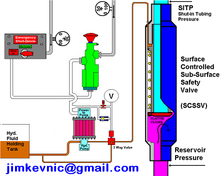
In case of SCSSV, a 1/4″ inch stainless steel control line is attached to the outside of the tubing string and installed when the tubing is installed. Depending on the wellhead pressure, it may be necessary to keep as much as 4000 to 5000 psi on the control line to keep the valve open.
The differential type subsurface controlled subsurface safety valve senses pressure drop across a flow bean. There are several variations of the differential type SSCSV. Although they employ different sealing devices, such as a flapper or ball, they all are controlled with a flow bean and spring tension.
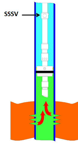
As shown in the following video, when hydraulic pressure is applied down a control line, the hydraulic pressure forces a sleeve within the valve to slide downwards. This movement compresses a large spring and pushes the flapper (in case of flapper type SCSSV) or the ball (in case of ball type SCSSV) downwards to open the valve. When hydraulic pressure is removed, the spring pushes the sleeve back up and causes the flapper (or the ball) to shut. In this way, it is failsafe and will isolate the wellbore in the event of a loss of the wellhead.
The location of the downhole safety valve within the completion is a precisely determined parameter intended to optimise safety. There are arguments against it either being too high or too low in the well and so the final depth is a compromise of all factors. MMS regulations state that the valve must be placed no less than 100′ below the mudline.

The safety device is established in the upper wellbore to administer emergency closure of the bearing conduits in the case of a disaster. Types of subsurface safety valves are surface-controlled and subsurface-controlled. In each case, the safety-valve system is invented to be fail-safe, so that the wellbore is isolated in the event of any system failure or damage to the surface production-control facilities.


 8613371530291