
safety valve plans factory

Avoid the headache, hassle and costly repair bills caused by a water or sewer emergency on your property, or an in-home plumbing problem. A single call to Safety Valve takes care of it all.
New to Safety Valve? Enter your address below to check eligibility. Already a customer? Log in to manage your account. You must register first if you haven"t done so.

To start a claim you must call Safety Valve directly at 1-800-713-1613. Work must be done by a Safety Valve referred contractor to be covered so do NOT call a contractor directly or your claim will not be covered.
The curb box allows access to the curb valve, and the curb valve is the valve located on your property that can be used to shut off the water in the event of an emergency water line leak.
The Water Line Protection Plan covers from where your water service line connects to your main water valve in your basement to the curb valve located on your property. In some instances, you may also own and be responsible for the water line in the street, which runs from your curb valve on your property to the water main in the street. (We suggest you contact your local water utility for clarification.)
No, the main shut-off valve in your home is not covered under the Water Line Protection Plan. It is the point where the water service line coming into your home ends. We consider the main valve as part of your internal plumbing. If you would like coverage for the main shut-off valve, please review our In-Home Plumbing Protection Plan.
All plans take effect 30 days after the enrollment is processed and payment received, regardless of whether you pay by check, bank account or with a credit card. In some cases, we may need to perform an on-site inspection, so we provide customers with a 30-day window to account for this possibility.

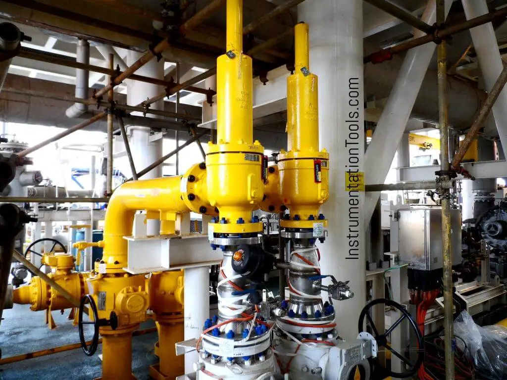
The Pressure Safety Valve Inspection article provides you information about inspection of pressure safety valve and pressure safety valve test in manufacturing shop as well as in operational plants.
Your pressure safety valve is a direct spring-loaded pressure-relief valve that is opened by the static pressure upstream of the valve and characterized by rapid opening or pop action.
Your construction code for pressure safety valve is API Standard 526 and covers the minimum requirements for design, materials, fabrication, inspection, testing, and commissioning.
These are:API Recommended Practice 520 for Sizing and SelectionAPI Recommended practice 521 Guideline for Pressure Relieving and Depressing SystemsAPI Recommended Practice 527 Seat Tightness of Pressure Relief Valves
For example if there is pressure vessel need to be installed in the state of Minnesota then the pressure vessel nameplate shall be U stamped and pressure vessel safety valve shall be UV stamped.
National Board Inspection Code (NBIC) have own certification scheme for pressure safety valves and using NB symbol. The NBIC code book for this certification is NB 18.
There are some other standards and codes which are used in pressure safety valve such as:ASME PTC 25 for pressure relief devices which majorly is used for assessment of testing facility and apparatus for safety valvesBS EN ISO 4126-1, 4126-2 and 4126-3 which is construction standard similar to API STD 526.
This API RP 527 might be used in conjunction of API RP 576 as testing procedure for seat tightness testing of pressure safety valve for periodical servicing and inspection.
These are only important points or summery of points for pressure safety valve in-service inspection and should not be assumed as pressure safety valve inspection procedure.
Pressure safety valve inspection procedure is comprehensive document which need to cover inspection methods to be employed, equipment and material to be used, qualification of inspection personnel involved and the sequence of the inspection activities as minimum.
You may use following content as summery of points for Pressure Safety Valve Inspection in operational plantDetermination pressure safety valve inspection interval based API STD 510 and API RP 576 requirementsInspection of inlet and outlet piping after pressure safety valve removal for any foulingInspection of pressure safety valve charge and discharge nozzles for possible deposit and corrosion productsTaking care for proper handling of pressure safety valves from unit to the valve shop. The detail of handling and transportation instruction is provided in API RP 576.Controlling of seals for being intact when the valves arrived to the valve shop.Making as received POP test and recording the relieving pressure.
If the POP pressure is higher than the set pressure the test need to be repeated and if in the second effort it was near to the set pressure it is because of deposit.If in the second effort it was not opened near to the set pressure either it was set wrongly or it was changed during the operationIf the pressure safety valve was not opened in 150% of set pressure it should be considered as stuck shut.If the pressure safety valve was opened below the set pressure the spring is weakenedMaking external visual inspection on pressure safety valve after POP test. The test need contain following item as minimum;the flanges for pitting and roughness
Making body wall thickness measurementDismantling of pressure safety valve if the result of as received POP test was not satisfactoryMaking detail and comprehensive visual and dimensional inspection on the dismantled valve parts (after cleaning)Making special attention to the dismantled valves seating surfaces inspection e.g. disk and seat for roughness, wear and damage which might cause valve leakage in serviceReplacing the damaged parts in dismantled valves based manufacture recommendation and API RP 576 requirementsMaking precise setting of the pressure safety valve after reassembly based manufacture recommendation or NB-18 requirements
Making at least two POP test after setting and making sure the deviation from set pressure is not more than 2 psi for valves with set pressure equal or less than 70 psi or 3% for valves with set pressure higher than 70 psiMaking valve tightness test for leakage purpose after approval of the setting pressure and POP tests. The test method and acceptance criteria must be according to the API RP 576.The API RP 527 also can be used for pressure safety valve tightness test.Recording and maintaining the inspection and testing results.
The primary purpose of a safety valve is to protect life, property and the environment. Safety valves are designed to open and release excess pressure from vessels or equipment and then close again.
The function of safety valves differs depending on the load or main type of the valve. The main types of safety valves are spring-loaded, weight-loaded and controlled safety valves.
Regardless of the type or load, safety valves are set to a specific set pressure at which the medium is discharged in a controlled manner, thus preventing overpressure of the equipment. In dependence of several parameters such as the contained medium, the set pressure is individual for each safety application.

Do you want to expand your knowledge in safety valve technology? You want to plan and operate your plant in an efficient way? You want to further qualify your maintenance team? For engineers, experts or career changers, LESER offers the ideal training in safety valve technology.
Get detailed knowledge in nine modules: From an introduction to overpressure protection to the operation and maintenance of safety valves and the sizing of complex technical requirements - expand your know-how now!
Technically precise, practice-oriented, interesting and with modern training methods, LESER offers a wide range of training courses. With application examples, cutaway models and individual parts, the technology of safety valves is explained in a practical way. In the LESER Chatroom the functions of the different safety valves are demonstrated live. You will assemble, disassemble and test safety valves.

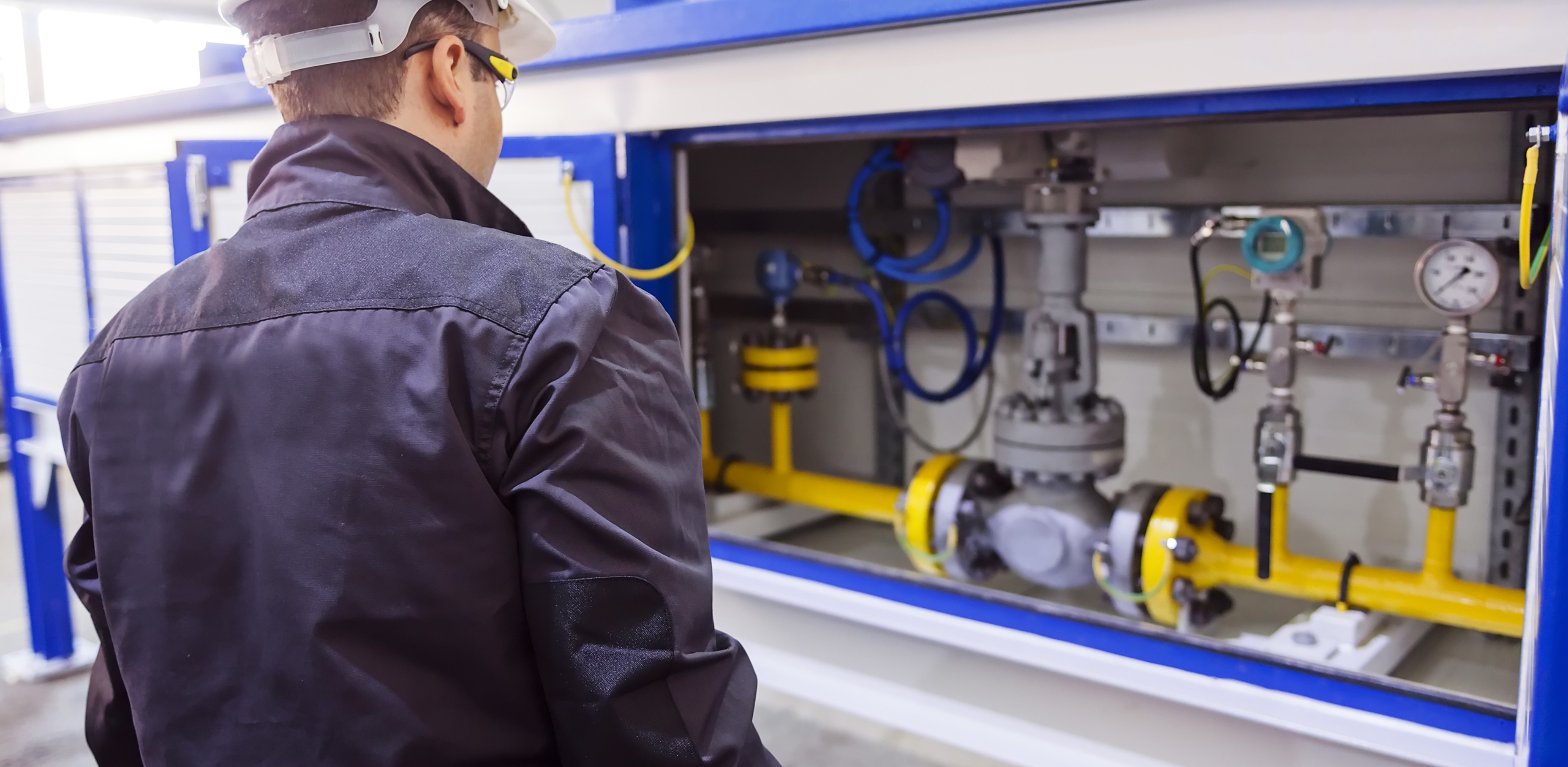
Safety valves are precision items of safety equipment; they are set to close tolerances and have accurately machined internal parts. They are susceptible to misalignment and damage if mishandled or incorrectly installed.
Valves should be transported upright if possible and they should never be carried or lifted by the easing lever. In addition, the protective plugs and flange protectors should not be removed until actual installation. Care should also be taken during movement of the valve to avoid subjecting it to excessive shock as this can result in considerable internal damage or misalignment.
When designing the inlet pipework, one of the main considerations is to ensure that the pressure drop in this pipework is minimised. EN ISO 4126 recommends that the pressure drop be kept below 3% of the set pressure when discharging. Where safety valves are connected using short ‘stub’ connections, inlet pipework must be at least the same size as the safety valve inlet connection. For larger lines or any line incorporating bends or elbows, the branch connection should be at least two pipe sizes larger than the safety valve inlet connection, at which point it is reduced in size to the safety valve inlet size (see Figure 9.5.5a). Excessive pressure loss can lead to ‘chatter’, which may result in reduced capacity and damage to the seating faces and other parts of the valve. In order to reduce the pressure loss in the inlet, the following methods can be adopted:
Safety valves should always be installed with the bonnet vertically upwards. Installing the valve in any other orientation can affect the performance characteristics.
The API Recommended Practice 520 guidelines also state that the safety valve should not be installed at the end of a long horizontal pipe that does not normally have flow through it. This can lead to the accumulation of foreign material or condensate in the pipe, which may cause unnecessary damage to the valve, or interfere with its operation.
There are two possible types of discharge system – open and closed. An open system discharges directly into the atmosphere whereas a closed system discharges into a manifold along with other safety valves.
It is recommended that discharge pipework should rise for steam and gas systems, whereas for liquids, it should fall. Horizontal pipework should have a downward gradient of at least 1 in 100 away from the valve ensuring that any discharge will be self-draining. It is important to drain any rising discharge pipework. Vertical rises will require separate drainage. Note: all points of system drainage are subject to the same precautions, notably that valve performance must not be affected, and any fluid must be discharged to a safe location.
It is essential to ensure that fluid cannot collect on the downstream side of a safety valve, as this will impair its performance and cause corrosion of the spring and internal parts. Many safety valves are provided with a body drain connection, if this is not used or not provided, then a small bore drain should be fitted in close proximity to the valve outlet (see Figure 9.5.3).
One of the main concerns in closed systems is the pressure drop or built-up backpressure in the discharge system. As mentioned in Module 9.2, this can drastically affect the performance of a safety valve. The EN ISO 4126: Part 1 standard states that the pressure drop should be maintained below 10% of the set pressure. In order to achieve this, the discharge pipe can be sized using Equation 9.5.1.
Calculate the nominal diameter of the discharge pipework for a safety valve required to discharge 1 000 kg/h of saturated steam; given that the steam is to be discharged into a vented tank via the pipework, which has an equivalent length of 25 m. The set pressure of the safety valve is 10 bar g and the acceptable backpressure is 10% of the set pressure. (Assume zero pressure drop along the tank vent).
Therefore, the pipework connected to the outlet of the safety valve should have an internal diameter of at least 54 mm. With schedule 40 pipe, this would require a DN65 pipe.
Balanced safety valves require that their bonnets be vented to atmosphere. In the case of the balanced bellows type, there will be no discharge of the process fluid, so they can be vented directly to the atmosphere. The main design consideration is to ensure that this vent will not become blocked, for example, by foreign material or ice. With the balanced piston type, consideration must be given to the fact that process fluid may be discharged through the bonnet vent. If discharging to a pressurised system, the vent has to be suitably sized, so that no backpressure exists above the piston.
Safety valves that are installed outside of a building for discharge directly into the atmosphere should be covered using a hood. The hood allows the discharge of the fluid, but prevents the build up of dirt and other debris in the discharge pipework, which could affect the backpressure. The hood should also be designed so that it too does not affect the backpressure.
Manifolds must be sized so that in the worst case (i.e. when all the manifold valves are discharging), the pipework is large enough to cope without generating unacceptable levels of backpressure. The volume of the manifold should ideally be increased as each valve outlet enters it, and these connections should enter the manifold at an angle of no greater than 45° to the direction of flow (see Figure 9.5.6). The manifold must also be properly secured and drained where necessary.
In open systems, careful consideration must be given to the effects of the reaction forces generated in the discharge system when the valve lifts. In these systems, there will be significant resultant force acting in the opposite direction to that of discharge. It is important to prevent excessive loads being imposed on the valve or the inlet connection by these reaction forces, as they can cause damage to the inlet pipework. The magnitude of the reaction forces can be calculated using the formula in Equation 9.5.2:
The reaction forces are typically small for safety valves with a nominal diameter of less than 75 mm, but safety valves larger than this usually have mounting flanges for a reaction bar on the body to allow the valve to be secured.
Regardless of the magnitude of the reaction forces, the safety valve itself should never be relied upon to support the discharge pipework itself and a support should be provided to resist the weight of the discharge pipework. This support should be located as close as possible to the centreline of the vent pipe (see Figure 9.5.7).
Changeover valves (see Figure 9.5.10) permit two valves to be mounted side by side, with one in service and one isolated. This means regular maintenance can be carried out without interruption of service or the vessel being protected. Changeover valves are designed in such a way that when they are operated, the pass area is never restricted.
Changeover valves can also be used to connect safety valve outlets so that the discharge pipework does not have to be duplicated. The action of both inlet and outlet changeover valves has to be limited and synchronised for safety reasons. This is usually by means of a chain drive system linking both handwheels.
Consideration must be made to pressure loss caused by the changeover valve when establishing the safety valve inlet pressure drop, which should be limited to 3% of the set pressure.

Industry leading pressure and safety relief valve designs with over 140 years of technical and application expertise providing custom engineered solutions for O&G, Refining, Chemical, Petrochemical, Process and Power applications. Our designs meet global and local codes and standards (API 526; ASME Section I, IV & VIII; EN ISO 4126; PED & more). Gain insight into the performance of your pressure relief valves with wireless monitoring.

In this article, we will provide a brief overview of some of the history related to relief valves and how we document them. Because this is an introductory article, there are some simplifications of concepts and language. For ease of reading, we are describing many different types of relief valves, including conventional, balanced bellows, and pilot operated, simply as “relief valves” for this article.
A relief valve is a safety device that protects equipment and piping from failure due to overpressure. Virtually all manufacturing plants and most of our homes have relief valves; for example, every home has a water heater that has a pressure relief valve to protect from high temperatures and pressures if the controls for the heating element fail.
A little bit of history can help us understand the importance of relief valves on these pieces of equipment, typically referred to as “pressure vessels”.
The April 9, 1998 explosion at the Herrig Brothers poultry farm provides a sober example of the damage these explosions can cause. According to the US Chemical Safety and Hazard Investigation Board, an 18,000-gallon propane tank caught fire and exploded, killing two volunteer firefighters and injuring seven other people. The propane tank fire started after an all-terrain vehicle crashed into unprotected above-ground propane piping that ran from the propane storage tank to process equipment. The collision triggered a propane leak under the tank, which eventually ignited and engulfed the tank. Because of the fire’s size, firefighters could not approach a manual shut-off valve to stop the leak, so they decided to spray the surrounding buildings to prevent the spread of fire and just let it burn itself out. Unfortunately, the fire engulfing the tank heated up the propane inside, building pressure until it ruptured and propelled fire and debris over 100 feet, killing two firefighters and injuring seven emergency response personnel in the vicinity of the propane tank. Two key problems led to this explosion: (1) there was not sufficient protection of the piping around the tank to prevent it from being damaged, and (2) the tank lines lacked an excess flow check valve that is frequently installed to limit un-controlled flow.
Interestingly, the majority of the failures occur during start up and shut down of processes because of transient changes (e.g., leaving a valve open or closed during start up). These failures can be mitigated by good design methodology, installation of properly sized relief devices, and continued maintenance of proper documentation.
A lot of the initial design methodology was simplistic and heuristic-based, consistent with the understanding and tools available at the time. In 1977, the American Institute of Chemical Engineers (AIChE) recognized the need to develop better methodology for reactions and two-phase relief, and set up a group, the Design Institute for Emergency Relief Systems (DIERS), to study and develop the tools to address the issues of relief valve design. Slightly later, the US government recognized that a common minimum design standard for relief design is required, so they codified it with OSHA 1910. One of the requirements is that the design of relief devices be documented. Many of the designs up to this point were documented with minimal descriptions and calculation explanations. Additionally, these designs were frequently not included in the files nor were they updated as the plant design changed.
Each of the pressure vessels, heat exchangers, operating equipment and piping (summarily called equipment) are designed to contain the system pressure. The MAWP for each item has to be considered to find the minimum (limiting) pressure that should be used as the set pressure for the relief valve. Here is an example of how the minimum set pressure can be understood. For the equipment limitations, a table is prepared showing the pressure and temperature limitations for the equipment and piping protected by the relief device. The maximum set pressure for the relief device will be derived from this table, an example of which is provided below:
This article provided a historical look at the development and impact of relief valves, their design, and the necessity of proper documentation for safety, but it was not an exhaustive look at the full range of possibilities of design and safety for pressure vessels. Matrix Technologies is one of the largest independent process design, industrial automation engineering, and manufacturing operations management companies in North America. To learn more about our process design services, contact Jeremy Runk, Department Manager of the Process & Electrical Design Department.
The Three Mile Island Unit 2 reactor, near Middletown, Pa., partially melted down on March 28, 1979. This was the most serious accident in U.S. commercial nuclear power plant operating history, although its small radioactive releases had no detectable health effects on plant workers or the public. Its aftermath brought about sweeping changes involving emergency response planning, reactor operator training, human factors engineering, radiation protection, and many other areas of nuclear power plant operations. It also caused the NRC to tighten and heighten its regulatory oversight. All of these changes significantly enhanced U.S. reactor safety.
The accident began about 4 a.m. on Wednesday, March 28, 1979, when the plant experienced a failure in the secondary, non-nuclear section of the plant (one of two reactors on the site). Either a mechanical or electrical failure prevented the main feedwater pumps—component (1) in the animated diagram)—from sending water to the steam generators (2) that remove heat from the reactor core (3). This caused the plant"s turbine-generator (4) and then the reactor itself to automatically shut down. Immediately, the pressure in the primary system (the nuclear piping portion of the plant shown in orange) began to increase. In order to control that pressure, the pilot-operated relief valve (5) opened. It was located at the top of the pressurizer (6). The valve should have closed when the pressure fell to proper levels, but it became stuck open. Instruments in the control room, however, indicated to the plant staff that the valve was closed. As a result, the plant staff was unaware that cooling water in the form of steam was pouring out of the stuck-open valve. As alarms rang and warning lights flashed, the operators did not realize that the plant was experiencing a loss-of-coolant accident.
Unaware of the stuck-open relief valve and unable to tell if the core was covered with cooling water, the staff took a series of actions that uncovered the core. The stuck valve reduced primary system pressure so much that the reactor coolant pumps (8) started to vibrate and were turned off. The emergency cooling water being pumped into the primary system threatened to fill up the pressurizer completely—an undesirable condition—and they cut back on the flow of water. Without the reactor coolant pumps circulating water and with the primary system starved of emergency cooling water, the water level in the pressure vessel dropped and the core overheated.
A combination of personnel error, design deficiencies, and component failures caused the TMI accident, which permanently changed both the nuclear industry and the NRC. Public fear and distrust increased, NRC’s regulations and oversight became broader and more robust, and management of the plants was scrutinized more carefully. Careful analysis of the accident’s events identified problems and led to permanent and sweeping changes in how NRC regulates its licensees – which, in turn, has reduced the risk to public health and safety.
Upgrading and strengthening of plant design and equipment requirements. This includes fire protection, piping systems, auxiliary feedwater systems, containment building isolation, reliability of individual components (pressure relief valves and electrical circuit breakers), and the ability of plants to shut down automatically;
Identifying the critical role of human performance in plant safety led to revamping operator training and staffing requirements, followed by improved instrumentation and controls for operating the plant, and establishment of fitness-for-duty programs for plant workers to guard against alcohol or drug abuse;
Enhancing emergency preparedness, including requirements for plants to immediately notify NRC of significant events and an NRC Operations Center staffed 24 hours a day. Drills and response plans are now tested by licensees several times a year, and state and local agencies participate in drills with the Federal Emergency Management Agency and the NRC;
Expanding performance-oriented as well as safety oriented inspections, and the use of risk assessment to identify vulnerabilities of any plant to severe accidents;
Enacting programs by licensees for early identification of important safety related problems, and for collecting and assessing relevant data so operating experience can be shared and quickly acted upon; and

Anderson Greenwood pressure relief valves, tank protection products, primary isolation valves, and instrumentation set the industry standard for repeatable service and long service life. The breadth of Anderson Greenwood product offerings for both standard and specialized installations combined with unmatched application expertise, product quality, and availability provides for complete valve solutions in the oil and gas, chemical, power generation, and refining industries.

For centuries, safety relief valves have served as a vital line of protection against excessive overpressure that – left unaddressed – can cause considerable damage to industrial processes including equipment failure and process upset, along with secondary hazards arising from an uncontrolled release of pressurized fluid.
These essential safety devices are designed to automatically open when the force exerted by the pressure reaches a setpoint to rapidly discharge the fluids. Once the overpressurization has dissipated, the valve recloses, conserving the remaining fluid.
In developing codes and standards, the industry has largely standardized around the 90-degree flow path design outlined by the American Petroleum Institute (API). This standardized approach requires a drop in pressure inside the valve before it discharges fluid from the exit nozzle.
To ensure proper performance, the orifice diameter at the inlet side is smaller than the nominal valve size, with an outlet diameter that is larger than both. A two by three-inch traditional API configuration safety relief valve will be designed with either a 0.785” diameter H orifice or a 1.287” diameter J orifice at its inlet and a three-inch outlet, for example.
While it may be convenient for the purposes of standardization, other approaches to safety relief valve design are possible while meeting industry codes and standards such as those published by The American Society Of Mechanical Engineers (ASME), said Geof Brazier, Managing Director, BS&B Safety Systems, Custom Engineered Products Division.
So, BS&B had a novel idea: what if the safety relief valve was an inline device, with outlet and inlet connections that were the same size and an inlet orifice diameter to match the inlet connection?
“With an inline design, the flow moves in a straight line and doesn’t have to change direction,” said Brazier. “The design allows for a certain amount of flow expansion, but we don’t have nearly the same level of turbulence inside the valve, which increases the capacity of the device,” said Brazier.
By having the inlet diameter match the nominal size of the valve, there is more flow [capacity]. The valve can also be more compact, lighter in weight and requires smaller size and therefore less expensive piping. The result is simplified installation and a lower total cost of investment.
To address the need for increased flow, BS&B has introduced the IDV Safety Valve, a self-reclosing safety pressure relief valve that functions the same as a traditional safety relief valve but with an inline configuration rather than the traditional angle body configuration.
The inline configuration allows for up to 3 times the capacity of a conventional valve. The smaller the nominal size, the greater the capacity benefit from the IDV Safety Valve.
This new technology enables customers to achieve the same overall outcome as a traditional valve. The increased capacity allows engineers and operators to optimize their pressure safety systems and, in many applications, reduce the piping configuration (line size) by one or more nominal sizes.
The IDV Safety Valve is compact and lightweight and can be installed using ANSI/ASME B 16.5 and international flange connections. Mounting can be either horizontal or vertical, adding to the flexibility of application for this design.
The valve can be combined with an optional integrated rupture disk at the inlet and/or outlet. The combination of a rupture disk device with a safety relief valve has many benefits arising from valve isolation to the normal process conditions including optimal leak tightness, increased operating pressure, extended valve life and reduced valve maintenance.
The IDV has already been installed in over 10,000 processes worldwide, making it an established alternative to the safety relief valve that meets the same codes and standards.

A group of eastern U.S. power grid operators says a “reliability safety valve” should be considered in any clean energy policy, to give utilities and other suppliers more time to meet wind and solar power goals when required to prevent power disruptions.
A safety valve provision would create a “timeout” to deal with a grid reliability issue in part or the grid as high levels of intermittent generation are reached. It would provide a “limited surgical opportunity” to deal with reliability issues as clean energy rules and timelines are carried out, EIPC said.
At the time, the Federal Energy Regulatory Commission proposed a safety valve provision in a letter to EPA, suggesting that the commission could review a state’s claims that an emergency situation would result in a violation of FERC-approved grid reliability safeguards.


 8613371530291