
safety valve plans brands

Avoid the headache, hassle and costly repair bills caused by a water or sewer emergency on your property, or an in-home plumbing problem. A single call to Safety Valve takes care of it all.
New to Safety Valve? Enter your address below to check eligibility. Already a customer? Log in to manage your account. You must register first if you haven"t done so.
![]()
Distributor of hydraulic press safety, quick opening safety, rotary and safety valves. Amerigear®, Boston Gear®, Carlisle®, DeMag®, Desch® and IMI Norgren®, pneumatic, double action, quick release and flow control valves also provided. Repair and preventative maintenance services are offered. Value added services such as custom barcoding, CAD capabilities, OEM assembly, plant surveys and third party logistics are also available. Serves the metal processing, metal service center, paper mill and paper converting, canning, grinding, commercial laundry, marine, oil and gas and material handling industries. Vendor managed inventory (VMI) programs available. Kanban delivery.
Of all the challenges you face keeping your customers’ plants operating at full capacity, safety and relief valves shouldn’t be one of them. NASVI’s job is to give you the confidence that your valve supply chain is rock solid regardless the pressure it’s under.

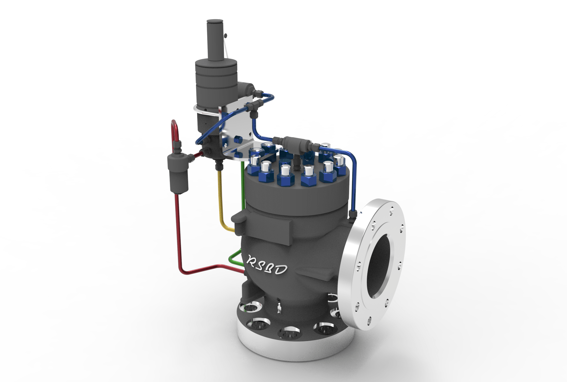
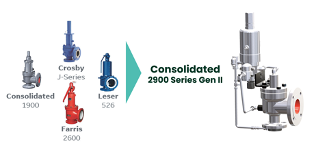
Industry leading pressure and safety relief valve designs with over 140 years of technical and application expertise providing custom engineered solutions for O&G, Refining, Chemical, Petrochemical, Process and Power applications. Our designs meet global and local codes and standards (API 526; ASME Section I, IV & VIII; EN ISO 4126; PED & more). Gain insight into the performance of your pressure relief valves with wireless monitoring.
This page lists the ApprovedPressure and Safety Relief ValveManufacturers (vendors), also provides inspection and test advice to thePressure and Safety Relief Valvepurchasers buying from vendors, suppliers and distributors.
There is a wide range of safety valves available to meet the many different applications and performance criteria demanded by different industries. Furthermore, national standards define many varying types of safety valve.
The ASME standard I and ASME standard VIII for boiler and pressure vessel applications and the ASME/ANSI PTC 25.3 standard for safety valves and relief valves provide the following definition. These standards set performance characteristics as well as defining the different types of safety valves that are used:
ASME I valve - A safety relief valve conforming to the requirements of Section I of the ASME pressure vessel code for boiler applications which will open within 3% overpressure and close within 4%. It will usually feature two blowdown rings, and is identified by a National Board ‘V’ stamp.
ASME VIII valve- A safety relief valve conforming to the requirements of Section VIII of the ASME pressure vessel code for pressure vessel applications which will open within 10% overpressure and close within 7%. Identified by a National Board ‘UV’ stamp.
Full bore safety valve - A safety valve having no protrusions in the bore, and wherein the valve lifts to an extent sufficient for the minimum area at any section, at or below the seat, to become the controlling orifice.
Conventional safety relief valve -The spring housing is vented to the discharge side, hence operational characteristics are directly affected by changes in the backpressure to the valve.
Balanced safety relief valve -A balanced valve incorporates a means of minimising the effect of backpressure on the operational characteristics of the valve.
Pilot operated pressure relief valve -The major relieving device is combined with, and is controlled by, a self-actuated auxiliary pressure relief device.
Power-actuated safety relief valve - A pressure relief valve in which the major pressure relieving device is combined with, and controlled by, a device requiring an external source of energy.
Standard safety valve - A valve which, following opening, reaches the degree of lift necessary for the mass flowrate to be discharged within a pressure rise of not more than 10%. (The valve is characterised by a pop type action and is sometimes known as high lift).
Full lift (Vollhub) safety valve -A safety valve which, after commencement of lift, opens rapidly within a 5% pressure rise up to the full lift as limited by the design. The amount of lift up to the rapid opening (proportional range) shall not be more than 20%.
Direct loaded safety valve -A safety valve in which the opening force underneath the valve disc is opposed by a closing force such as a spring or a weight.
Proportional safety valve - A safety valve which opens more or less steadily in relation to the increase in pressure. Sudden opening within a 10% lift range will not occur without pressure increase. Following opening within a pressure of not more than 10%, these safety valves achieve the lift necessary for the mass flow to be discharged.
Diaphragm safety valve -A direct loaded safety valve wherein linear moving and rotating elements and springs are protected against the effects of the fluid by a diaphragm
Bellows safety valve - A direct loaded safety valve wherein sliding and (partially or fully) rotating elements and springs are protected against the effects of the fluids by a bellows. The bellows may be of such a design that it compensates for influences of backpressure.
Controlled safety valve - Consists of a main valve and a control device. It also includes direct acting safety valves with supplementary loading in which, until the set pressure is reached, an additional force increases the closing force.
Safety valve - A safety valve which automatically, without the assistance of any energy other than that of the fluid concerned, discharges a quantity of the fluid so as to prevent a predetermined safe pressure being exceeded, and which is designed to re-close and prevent further flow of fluid after normal pressure conditions of service have been restored. Note; the valve can be characterised either by pop action (rapid opening) or by opening in proportion (not necessarily linear) to the increase in pressure over the set pressure.
Direct loaded safety valve -A safety valve in which the loading due to the fluid pressure underneath the valve disc is opposed only by a direct mechanical loading device such as a weight, lever and weight, or a spring.
Assisted safety valve -A safety valve which by means of a powered assistance mechanism, may additionally be lifted at a pressure lower than the set pressure and will, even in the event of a failure of the assistance mechanism, comply with all the requirements for safety valves given in the standard.
Supplementary loaded safety valve - A safety valve that has, until the pressure at the inlet to the safety valve reaches the set pressure, an additional force, which increases the sealing force.
Note; this additional force (supplementary load), which may be provided by means of an extraneous power source, is reliably released when the pressure at the inlet of the safety valve reaches the set pressure. The amount of supplementary loading is so arranged that if such supplementary loading is not released, the safety valve will attain its certified discharge capacity at a pressure not greater than 1.1 times the maximum allowable pressure of the equipment to be protected.
Pilot operated safety valve -A safety valve, the operation of which is initiated and controlled by the fluid discharged from a pilot valve, which is itself, a direct loaded safety valve subject to the requirement of the standard.
The common characteristic shared between the definitions of conventional safety valves in the different standards, is that their operational characteristics are affected by any backpressure in the discharge system. It is important to note that the total backpressure is generated from two components; superimposed backpressure and the built-up backpressure:
Subsequently, in a conventional safety valve, only the superimposed backpressure will affect the opening characteristic and set value, but the combined backpressure will alter the blowdown characteristic and re-seat value.
The ASME/ANSI standard makes the further classification that conventional valves have a spring housing that is vented to the discharge side of the valve. If the spring housing is vented to the atmosphere, any superimposed backpressure will still affect the operational characteristics. Thiscan be seen from Figure 9.2.1, which shows schematic diagrams of valves whose spring housings are vented to the discharge side of the valve and to the atmosphere.
By considering the forces acting on the disc (with area AD), it can be seen that the required opening force (equivalent to the product of inlet pressure (PV) and the nozzle area (AN)) is the sum of the spring force (FS) and the force due to the backpressure (PB) acting on the top and bottom of the disc. In the case of a spring housing vented to the discharge side of the valve (an ASME conventional safety relief valve, see Figure 9.2.1 (a)), the required opening force is:
In both cases, if a significant superimposed backpressure exists, its effects on the set pressure need to be considered when designing a safety valve system.
Once the valve starts to open, the effects of built-up backpressure also have to be taken into account. For a conventional safety valve with the spring housing vented to the discharge side of the valve, see Figure 9.2.1 (a), the effect of built-up backpressure can be determined by considering Equation 9.2.1 and by noting that once the valve starts to open, the inlet pressure is the sum of the set pressure, PS, and the overpressure, PO.
Balanced safety valves are those that incorporate a means of eliminating the effects of backpressure. There are two basic designs that can be used to achieve this:
Although there are several variations of the piston valve, they generally consist of a piston type disc whose movement is constrained by a vented guide. The area of the top face of the piston, AP, and the nozzle seat area, AN, are designed to be equal. This means that the effective area of both the top and bottom surfaces of the disc exposed to the backpressure are equal, and therefore any additional forces are balanced. In addition, the spring bonnet is vented such that the top face of the piston is subjected to atmospheric pressure, as shown in Figure 9.2.2.
The bellows arrangement prevents backpressure acting on the upper side of the disc within the area of the bellows. The disc area extending beyond the bellows and the opposing disc area are equal, and so the forces acting on the disc are balanced, and the backpressure has little effect on the valve opening pressure.
Bellows failure is an important concern when using a bellows balanced safety valve, as this may affect the set pressure and capacity of the valve. It is important, therefore, that there is some mechanism for detecting any uncharacteristic fluid flow through the bellows vents. In addition, some bellows balanced safety valves include an auxiliary piston that is used to overcome the effects of backpressure in the case of bellows failure. This type of safety valve is usually only used on critical applications in the oil and petrochemical industries.
Since balanced pressure relief valves are typically more expensive than their unbalanced counterparts, they are commonly only used where high pressure manifolds are unavoidable, or in critical applications where a very precise set pressure or blowdown is required.
This type of safety valve uses the flowing medium itself, through a pilot valve, to apply the closing force on the safety valve disc. The pilot valve is itself a small safety valve.
The diaphragm type is typically only available for low pressure applications and it produces a proportional type action, characteristic of relief valves used in liquid systems. They are therefore of little use in steam systems, consequently, they will not be considered in this text.
The piston type valve consists of a main valve, which uses a piston shaped closing device (or obturator), and an external pilot valve. Figure 9.2.4 shows a diagram of a typical piston type, pilot operated safety valve.
The piston and seating arrangement incorporated in the main valve is designed so that the bottom area of the piston, exposed to the inlet fluid, is less than the area of the top of the piston. As both ends of the piston are exposed to the fluid at the same pressure, this means that under normal system operating conditions, the closing force, resulting from the larger top area, is greater than the inlet force. The resultant downward force therefore holds the piston firmly on its seat.
If the inlet pressure were to rise, the net closing force on the piston also increases, ensuring that a tight shut-off is continually maintained. However, when the inlet pressure reaches the set pressure, the pilot valve will pop open to release the fluid pressure above the piston. With much less fluid pressure acting on the upper surface of the piston, the inlet pressure generates a net upwards force and the piston will leave its seat. This causes the main valve to pop open, allowing the process fluid to be discharged.
When the inlet pressure has been sufficiently reduced, the pilot valve will reclose, preventing the further release of fluid from the top of the piston, thereby re-establishing the net downward force, and causing the piston to reseat.
Pilot operated safety valves offer good overpressure and blowdown performance (a blowdown of 2% is attainable). For this reason, they are used where a narrow margin is required between the set pressure and the system operating pressure. Pilot operated valves are also available in much larger sizes, making them the preferred type of safety valve for larger capacities.
One of the main concerns with pilot operated safety valves is that the small bore, pilot connecting pipes are susceptible to blockage by foreign matter, or due to the collection of condensate in these pipes. This can lead to the failure of the valve, either in the open or closed position, depending on where the blockage occurs.
The terms full lift, high lift and low lift refer to the amount of travel the disc undergoes as it moves from its closed position to the position required to produce the certified discharge capacity, and how this affects the discharge capacity of the valve.
A full lift safety valve is one in which the disc lifts sufficiently, so that the curtain area no longer influences the discharge area. The discharge area, and therefore the capacity of the valve are subsequently determined by the bore area. This occurs when the disc lifts a distance of at least a quarter of the bore diameter. A full lift conventional safety valve is often the best choice for general steam applications.
The disc of a high lift safety valve lifts a distance of at least 1/12th of the bore diameter. This means that the curtain area, and ultimately the position of the disc, determines the discharge area. The discharge capacities of high lift valves tend to be significantly lower than those of full lift valves, and for a given discharge capacity, it is usually possible to select a full lift valve that has a nominal size several times smaller than a corresponding high lift valve, which usually incurs cost advantages.Furthermore, high lift valves tend to be used on compressible fluids where their action is more proportional.
In low lift valves, the disc only lifts a distance of 1/24th of the bore diameter. The discharge area is determined entirely by the position of the disc, and since the disc only lifts a small amount, the capacities tend to be much lower than those of full or high lift valves.
Except when safety valves are discharging, the only parts that are wetted by the process fluid are the inlet tract (nozzle) and the disc. Since safety valves operate infrequently under normal conditions, all other components can be manufactured from standard materials for most applications. There are however several exceptions, in which case, special materials have to be used, these include:
Cast steel -Commonly used on higher pressure valves (up to 40 bar g). Process type valves are usually made from a cast steel body with an austenitic full nozzle type construction.
For all safety valves, it is important that moving parts, particularly the spindle and guides are made from materials that will not easily degrade or corrode. As seats and discs are constantly in contact with the process fluid, they must be able to resist the effects of erosion and corrosion.
The spring is a critical element of the safety valve and must provide reliable performance within the required parameters. Standard safety valves will typically use carbon steel for moderate temperatures. Tungsten steel is used for higher temperature, non-corrosive applications, and stainless steel is used for corrosive or clean steam duty. For sour gas and high temperature applications, often special materials such as monel, hastelloy and ‘inconel’ are used.
Standard safety valves are generally fitted with an easing lever, which enables the valve to be lifted manually in order to ensure that it is operational at pressures in excess of 75% of set pressure. This is usually done as part of routine safety checks, or during maintenance to prevent seizing. The fitting of a lever is usually a requirement of national standards and insurance companies for steam and hot water applications. For example, the ASME Boiler and Pressure Vessel Code states that pressure relief valves must be fitted with a lever if they are to be used on air, water over 60°C, and steam.
A test gag (Figure 9.2.7) may be used to prevent the valve from opening at the set pressure during hydraulic testing when commissioning a system. Once tested, the gag screw is removed and replaced with a short blanking plug before the valve is placed in service.
The amount of fluid depends on the particular design of safety valve. If emission of this fluid into the atmosphere is acceptable, the spring housing may be vented to the atmosphere – an open bonnet. This is usually advantageous when the safety valve is used on high temperature fluids or for boiler applications as, otherwise, high temperatures can relax the spring, altering the set pressure of the valve. However, using an open bonnet exposes the valve spring and internals to environmental conditions, which can lead to damage and corrosion of the spring.
When the fluid must be completely contained by the safety valve (and the discharge system), it is necessary to use a closed bonnet, which is not vented to the atmosphere. This type of spring enclosure is almost universally used for small screwed valves and, it is becoming increasingly common on many valve ranges since, particularly on steam, discharge of the fluid could be hazardous to personnel.
Some safety valves, most commonly those used for water applications, incorporate a flexible diaphragm or bellows to isolate the safety valve spring and upper chamber from the process fluid, (see Figure 9.2.9).

Curtiss-Wright"s selection of Pressure Relief Valves comes from its outstanding product brands Farris and Target Rock. We endeavor to support the whole life cycle of a facility and continuously provide custom products and technologies. Boasting a reputation for producing high quality, durable products, our collection of Pressure Relief Valves is guaranteed to provide effective and reliable pressure relief.
While some basic components and activations in relieving pressure may differ between the specific types of relief valves, each aims to be 100% effective in keeping your equipment running safely. Our current range includes numerous valve types, from flanged to spring-loaded, threaded to wireless, pilot operated, and much more.
A pressure relief valve is a type of safety valve designed to control the pressure in a vessel. It protects the system and keeps the people operating the device safely in an overpressure event or equipment failure.
A pressure relief valve is designed to withstand a maximum allowable working pressure (MAWP). Once an overpressure event occurs in the system, the pressure relief valve detects pressure beyond its design"s specified capability. The pressure relief valve would then discharge the pressurized fluid or gas to flow from an auxiliary passage out of the system.
Below is an example of one of our pilot operated pressure relief valves in action; the cutaway demonstrates when high pressure is released from the system.
Air pressure relief valves can be applied to a variety of environments and equipment. Pressure relief valves are a safety valve used to keep equipment and the operators safe too. They"re instrumental in applications where proper pressure levels are vital for correct and safe operation. Such as oil and gas, power generation like central heating systems, and multi-phase applications in refining and chemical processing.
At Curtiss-Wright, we provide a range of different pressure relief valves based on two primary operations – spring-loaded and pilot operated. Spring-loaded valves can either be conventional spring-loaded or balanced spring-loaded.
Spring-loaded valves are programmed to open and close via a spring mechanism. They open when the pressure reaches an unacceptable level to release the material inside the vessel. It closes automatically when the pressure is released, and it returns to an average operating level. Spring-loaded safety valves rely on the closing force applied by a spring onto the main seating area. They can also be controlled in numerous ways, such as a remote, control panel, and computer program.
Pilot-operated relief valves operate by combining the primary relieving device (main valve) with self-actuated auxiliary pressure relief valves, also known as the pilot control. This pilot control dictates the opening and closing of the main valve and responds to system pressure. System pressure is fed from the inlet into and through the pilot control and ultimately into the main valve"s dome. In normal operating conditions, system pressure will prevent the main valve from opening.
The valves allow media to flow from an auxiliary passage and out of the system once absolute pressure is reached, whether it is a maximum or minimum level.
When the pressure is below the maximum amount, the pressure differential is slightly positive on the piston"s dome size, which keeps the main valve in the closed position. When system pressure rises and reaches the set point, the pilot will cut off flow to the dome, causing depressurization in the piston"s dome side. The pressure differential has reversed, and the piston will rise, opening the main valve, relieving pressure.
When the process pressure decreases to a specific pressure, the pilot closes, the dome is repressurized, and the main valve closes. The main difference between spring-loaded PRVs and pilot-operated is that a pilot-operated safety valve uses pressure to keep the valve closed.
Pilot-operated relief valves are controlled by hand and are typically opened often through a wheel or similar component. The user opens the valve when the gauge signifies that the system pressure is at an unsafe level; once the valve has opened and the pressure has been released, the operator can shut it by hand again.
Increasing pressure helps to maintain the pilot"s seal. Once the setpoint has been reached, the valve opens. This reduces leakage and fugitive emissions.
At set pressure the valve snaps to full lift. This can be quite violent on large pipes with significant pressure. The pressure has to drop below the set pressure in order for the piston to reseat.
At Curtiss-Wright we also provide solutions for pressure relief valve monitoring. Historically, pressure relief valves have been difficult or impossible to monitor. Our SmartPRV features a 2600 Series pressure relief valve accessorized with a wireless position monitor that alerts plant operators during an overpressure event, including the time and duration.
There are many causes of overpressure, but the most common ones are typically blocked discharge in the system, gas blowby, and fire. Even proper inspection and maintenance will not eliminate the occurrence of leakages. An air pressure relief valve is the only way to ensure a safe environment for the device, its surroundings, and operators.
A PRV and PSV are interchangeable, but there is a difference between the two valves. A pressure release valve gradually opens when experiencing pressure, whereas a pressure safety valve opens suddenly when the pressure hits a certain level of over pressurization. Safety valves can be used manually and are typically used for a permanent shutdown. Air pressure relief valves are used for operational requirements, and they gently release the pressure before it hits the maximum high-pressure point and circulates it back into the system.
Pressure relief valves should be subject to an annual test, one per year. The operator is responsible for carrying out the test, which should be done using an air compressor. It’s imperative to ensure pressure relief valves maintain their effectiveness over time and are checked for signs of corrosion and loss of functionality. Air pressure relief valves should also be checked before their installation, after each fire event, and regularly as decided by the operators.
Direct-acting solenoid valves have a direct connection with the opening and closing armature, whereas pilot-operated valves use of the process fluid to assist in piloting the operation of the valve.
A control valve works by varying the rate of fluid passing through the valve itself. As the valve stem moves, it alters the size of the passage and increases, decreases or holds steady the flow. The opening and closing of the valve is altered whenever the controlled process parameter does not reach the set point.
Control valves are usually at floor level or easily accessible via platforms. They are also located on the same equipment or pipeline as the measurement and downstream or flow measurements.
An industrial relief valve is designed to control or limit surges of pressure in a system, most often in fluid or compressed air system valves. It does so as a form of protection for the system and defending against instrument or equipment failure. They are usually present in clean water industries.
A PRV is often referred to as a pressure relief valve, which is also known as a PSV or pressure safety valve. They are used interchangeably throughout the industry depending on company standards.

Safety relief valves often serve as the point-of-protection against potentially dangerous circumstances, so it is important that they be dependable. Baker Hughes provides various valve styles, sizes, options and configurations for multiple industries and applications.
Baker Hughes continues to pursue quality and pro-active approach through regular collaboration with our customers and by staying actively involved in the development of regulatory compliance standards. We configure, engineer, and manufacture safety relief valves that adhere to industry regulations and global and regional standards while helping meet our customers’ evolving needs.
Not sure which valve you need for your application?Download ValSpeQ (Mooney regulators & Becker valves) or ValvStream™ (Masoneilan and Consolidated valves) to size, select and generate proposal documentation for your valves.
Consolidated Green Tag Centers (GTC) from Baker Hughes Energy comprise one of the broadest OEM service networks in the industry. With more than 80 facilities located in more than 30 countries worldwide, the GTCNet™ network provides the aftermarket support you need. Our GTC customers receive responsive and effective service through OEM-certified repairs, innovative valve diagnostics from ValvKeep™- valve management and maintenance software, and the EVT-Pro, an electronic valve testing device. Each GTC location is staffed with highly qualified technicians, specifically trained and certified to deliver exceptional product support and technical expertise.

Surface-controlled subsurface safety valves (SCSSVs) are critical components of well completions, preventing uncontrolled flow in the case of catastrophic damage to wellhead equipment. Fail-safe closure must be certain to ensure proper security of the well. However, this is not the only function in which it must be reliable—the valve must remain open to produce the well. Schlumberger surface controlled subsurface safety valves exceed all ISO 10432 and API Spec 14A requirements for pressure integrity, leakage acceptance criteria, and slam closure.
Through decades of innovation and experience, Schlumberger safety valve flapper systems are proven robust and reliable. The multizone dynamic seal technology for hydraulic actuation of subsurface safety valves is a further improvement in reliability performance when compared with traditional seal systems in the industry.
The multizone seal technology is currently available in the GeoGuard high-performance deepwater safety valves, which is validated to API Spec 14A V1 and V1-H.

Dante Valve is a full-service manufacturer, distributor and VR™ certified repair facility of valves and related products for the industrial and military markets.
We manufacture military specification Danco pressure relief valves; we distribute Kunkle relief valves and TRAC regulating, reducing, and temperature regulating valves, fittings and flanges; we also provide CNC machining services.

Service Sentinel℠ is not an active program at this time. With the acquisition of New England Service Company (NESC) by Aquarion Water Company (AWC), Service Sentinel has been merged into an entity called Safety Valve. Safety Valve is very similar to Service Sentinel, although there are some minor differences which can be explored online at www.safetyvalveplans.com. Safety Valve is a well-respected company that has partnerships with municipalities as large as New Britain, CT and Waterbury, CT. In addition, partnerships that Service Sentinel maintained with certain local water companies are being maintained, meaning that you will be able to rely on Safety Valve to provide the same standard of care and responsiveness that our customers have come to expect from Service Sentinel.
Furthermore, Safety Valve provides customers with several plans that Service Sentinel was not able to offer. In addition to water line coverage and a water and sewer line combo plan, Safety Valve offers both sewer line only coverage, as well as an in-home plumbing plan which can save you considerable time and resources in fixing broken pipes or clogged drains inside of your home or place of business.
Again, please visit www.safetyvalveplans.com for more details, and to enroll or renew existing coverage. Additional information can be found by calling 860-747-1665 (NESC) or 800-713-1613 (Safety Valve).

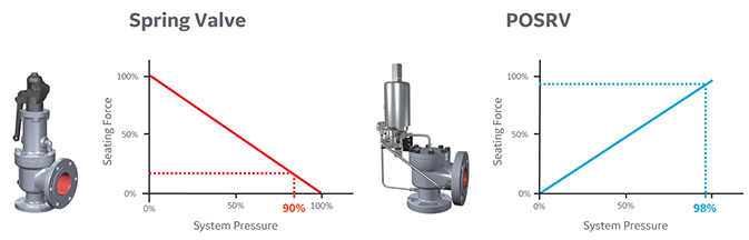
The pressure below the valve must increase above the set pressurebefore the safety valve reaches a noticeable lift. As a result of the restriction of flow between the disc and the adjusting ring, pressure builds up in the huddling chamber. The pressure now acts on an enlarged disc area. This increases the force Fp so that the additional spring force required to further compress the spring is overcome. The valve will open rapidly with a "pop", in most cases to its full lift.
Overpressure is the pressure increase above the set pressurenecessary for the safety valve to achieve full lift and capacity. The overpressure is usually expressed as a percentage of the set pressure. Codes and standards provide limits for the maximum overpressure. A typical value is 10%, ranging between 3% and 21% depending on the code and application.

Trillium Flow Technologies™, founded on a legacy of premier products and service, will continue to provide mission critical valves, pumps, and aftermarket services in oil and gas, power generation, water and wastewater, and general industry.
The IntelliStation Jr. Digital Mixing Valve is now enhanced with IoT capabilities! Achieve safety at a glance with remote visibility and control through your computer, or through your phone with the Watts OnSite mobile app.
Precise, Tool-less Balancing in 10 Seconds. Get the job done faster with iDROSET CSD, the only calibrated flow measuring and static balancing valve that lets you set and read the flow without any additional tools.
Pressure relief valves (safety relief valves) are designed to open at a preset pressure and discharge fluid until pressure drops to acceptable levels. The development of the safety relief valve has an interesting history.
Denis Papin is credited by many sources as the originator of the first pressure relief valve (circa 1679) to prevent overpressure of his steam powered “digester”. His pressure relief design consisted of a weight suspended on a lever arm. When the force of the steam pressure acting on the valve exceeded the force of the weight acting through the lever arm the valve opened. Designs requiring a higher relief pressure setting required a longer lever arm and/or larger weights. This simple system worked however more space was needed and it coud be easily tampered with leading to a possible overpressure and explosion. Another disadvantage was premature opening of the valve if the device was subjected to bouncing movement.
Direct-acting deadweight pressure relief valves: Later to avoid the disadvantages of the lever arrangement, direct-acting deadweight pressure relief valves were installed on early steam locomotives. In this design, weights were applied directly to the top of the valve mechanism. To keep the size of the weights in a reasonable range, the valve size was often undersized resulting in a smaller vent opening than required. Often an explosion would occur as the steam pressure rose faster than the vent could release excess pressure. Bouncing movements also prematurely released pressure.
Direct acting spring valves: Timothy Hackworth is believed to be the first to use direct acting spring valves (circa 1828) on his locomotive engine called the Royal George. Timothy utilized an accordion arrangement of leaf springs, which would later be replaced with coil springs, to apply force to the valve. The spring force could be fine tuned by adjusting the nuts retaining the leaf springs.
Refinements to the direct acting spring relief valve design continued in subsequent years in response to the widespread use of steam boilers to provide heat and to power locomotives, river boats, and pumps. Steam boilers are less common today but the safety relief valve continues to be a critical component, in systems with pressure vessels, to protect against damage or catastrophic failure.
Each application has its own unique requirements but before we get into the selection process, let’s have a look at the operating principles of a typical direct acting pressure relief valve.
In operation, the pressure relief valve remains normally closed until pressures upstream reaches the desired set pressure. The valve will crack open when the set pressure is reached, and continue to open further, allowing more flow as over pressure increases. When upstream pressure falls a few psi below the set pressure, the valve will close again.
Most commonly, pressure relief valves employ a spring loaded “poppet” valve as a valve element. The poppet includes an elastomeric seal or, in some high pressure designs a thermoplastic seal, which is configured to make a seal on a valve seat. In operation, the spring and upstream pressure apply opposing forces on the valve. When the force of the upstream pressure exerts a greater force than the spring force, then the poppet moves away from the valve seat which allows fluid to pass through the outlet port. As the upstream pressure drops below the set point the valve then closes.
Piston style designs are often used when higher relief pressures are required, when ruggedness is a concern or when the relief pressure does not have to be held to a tight tolerance. Piston designs tend to be more sluggish, compared to diaphragm designs due to friction from the piston seal. In low pressure applications, or when high accuracy is required, the diaphragm style is preferred. Diaphragm relief valves employ a thin disc shaped element which is used to sense pressure changes. They are usually made of an elastomer, however, thin convoluted metal is used in special applications. Diaphragms essentially eliminate the friction inherent with piston style designs. Additionally, for a particular relief valve size, it is often possible to provide a greater sensing area with a diaphragm design than would be feasible with a piston style design.
The reference force element is usually a mechanical spring. This spring exerts a force on the sensing element and acts to close the valve. Many pressure relief valves are designed with an adjustment which allows the user to adjust the relief pressure set-point by changing the force exerted by the reference spring.
The chemical properties of the fluid should be considered before determining the best materials for your application. Each fluid will have its own unique characteristics so care must be taken to select the appropriate body and seal materials that will come in contact with the fluid. The parts of the pressure relief valve in contact with the fluid are known as the “wetted” components. If the fluid is flammable or hazardous in nature the pressure relief valve must be capable of discharging it safely.
In many high technology applications space is limited and weight is a factor. Some manufactures specialize in miniature components and should be consulted. Material selection, particularly the relief valve body components, will impact weight. Also carefully consider the port (thread) sizes, adjustment styles, and mounting options as these will influence size and weight.
In many high technology applications space is limited and weight is a factor. Some manufactures specialize in miniature components and should be consulted. Material selection, particularly the relief valve body components, will impact weight. Also carefully consider the port (thread) sizes, adjustment styles, and mounting options as these will influence size and weight.
A wide range of materials are available to handle various fluids and operating environments. Common pressure relief valve component materials include brass, plastic, and aluminum. Various grades of stainless steel (such as 303, 304, and 316) are available too. Springs used inside the relief valve are typically made of music wire (carbon steel) or stainless steel.
The materials selected for the pressure relief valve not only need to be compatible with the fluid but also must be able to function properly at the expected operating temperature. The primary concern is whether or not the elastomer chosen will function properly throughout the expected temperature range. Additionally, the operating temperature may affect flow capacity and/or the spring rate in extreme applications.
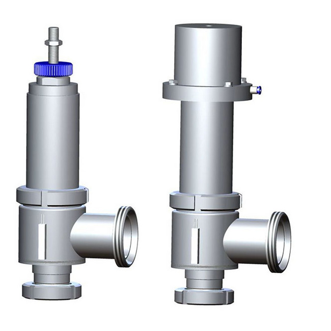
Beswick Engineering manufactures four styles of pressure relief valves to best suit your application. The RVD and RVD8 are diaphragm based pressure relief valves which are suited to lower relief pressures. The RV2 and BPR valves are piston based designs.
Vent-O-Mat offers effective air release vacuum protection and surge alleviation for water, sewage, and effluent pipelines. Vent-O-Mat’s distinguished line of air release valves are unsurpassed for performance and durability.
Vent-O-Mat is on the cutting edge of air valve design technology. This premium air release valve outperforms the competition: in addition to its air valve functions, it successfully assists in the elimination of surge and water hammer as a standard and automatic function.
Today, we find that our customers are struggling with this balancing act, particularly with severe service isolation valves. Engineering and maintenance departments have relied upon traditional valve technologies and have instituted rigorous maintenance practices and procedures to ensure that catastrophic valve failures do not occur, thus impacting operations with serious consequences. Even though a plant’s approved valve specification for a particular severe service application may have weaknesses, aggressive maintenance plans can keep valves from failing, but at a high cost in terms of materials and labor costs.
An approved valve specification and maintenance plan is a known entity, and historically a known and established life-cycle cost represented the lowest risk scenario. Industrial markets are now more dynamic than ever, putting an ever increasing pressure on margins. Buyers are becoming more price sensitive and maintenance departments are being asked to deliver improved KPI’s (Key Performance Indicators) with lower annual budgets. It must be acknowledged that even with these financial pressures, changing a valve specification for a severe service application does introduce risk. So how can you optimally mitigate risk while looking to deploy a modern valve technology? We offer three recommendations with examples.


 8613371530291