
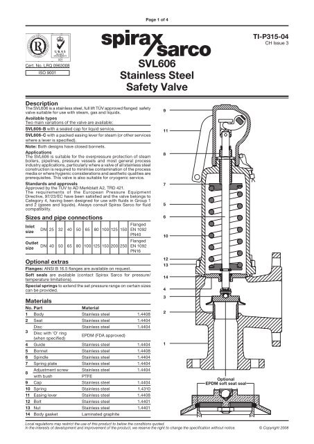
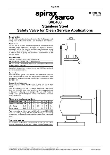
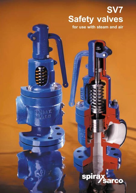
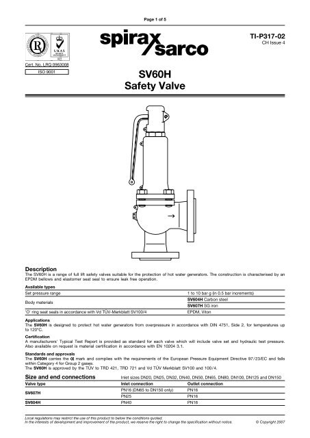
spirax sarco safety valve free sample
A safety valve must always be sized and able to vent any source of steam so that the pressure within the protected apparatus cannot exceed the maximum allowable accumulated pressure (MAAP). This not only means that the valve has to be positioned correctly, but that it is also correctly set. The safety valve must then also be sized correctly, enabling it to pass the required amount of steam at the required pressure under all possible fault conditions.
Once the type of safety valve has been established, along with its set pressure and its position in the system, it is necessary to calculate the required discharge capacity of the valve. Once this is known, the required orifice area and nominal size can be determined using the manufacturer’s specifications.
In order to establish the maximum capacity required, the potential flow through all the relevant branches, upstream of the valve, need to be considered.
In applications where there is more than one possible flow path, the sizing of the safety valve becomes more complicated, as there may be a number of alternative methods of determining its size. Where more than one potential flow path exists, the following alternatives should be considered:
This choice is determined by the risk of two or more devices failing simultaneously. If there is the slightest chance that this may occur, the valve must be sized to allow the combined flows of the failed devices to be discharged. However, where the risk is negligible, cost advantages may dictate that the valve should only be sized on the highest fault flow. The choice of method ultimately lies with the company responsible for insuring the plant.
For example, consider the pressure vessel and automatic pump-trap (APT) system as shown in Figure 9.4.1. The unlikely situation is that both the APT and pressure reducing valve (PRV ‘A’) could fail simultaneously. The discharge capacity of safety valve ‘A’ would either be the fault load of the largest PRV, or alternatively, the combined fault load of both the APT and PRV ‘A’.
This document recommends that where multiple flow paths exist, any relevant safety valve should, at all times, be sized on the possibility that relevant upstream pressure control valves may fail simultaneously.
The supply pressure of this system (Figure 9.4.2) is limited by an upstream safety valve with a set pressure of 11.6 bar g. The fault flow through the PRV can be determined using the steam mass flow equation (Equation 3.21.2):
Once the fault load has been determined, it is usually sufficient to size the safety valve using the manufacturer’s capacity charts. A typical example of a capacity chart is shown in Figure 9.4.3. By knowing the required set pressure and discharge capacity, it is possible to select a suitable nominal size. In this example, the set pressure is 4 bar g and the fault flow is 953 kg/h. A DN32/50 safety valve is required with a capacity of 1 284 kg/h.
Coefficients of discharge are specific to any particular safety valve range and will be approved by the manufacturer. If the valve is independently approved, it is given a ‘certified coefficient of discharge’.
This figure is often derated by further multiplying it by a safety factor 0.9, to give a derated coefficient of discharge. Derated coefficient of discharge is termed Kdr= Kd x 0.9
Critical and sub-critical flow - the flow of gas or vapour through an orifice, such as the flow area of a safety valve, increases as the downstream pressure is decreased. This holds true until the critical pressure is reached, and critical flow is achieved. At this point, any further decrease in the downstream pressure will not result in any further increase in flow.
A relationship (called the critical pressure ratio) exists between the critical pressure and the actual relieving pressure, and, for gases flowing through safety valves, is shown by Equation 9.4.2.
Overpressure - Before sizing, the design overpressure of the valve must be established. It is not permitted to calculate the capacity of the valve at a lower overpressure than that at which the coefficient of discharge was established. It is however, permitted to use a higher overpressure (see Table 9.2.1, Module 9.2, for typical overpressure values). For DIN type full lift (Vollhub) valves, the design lift must be achieved at 5% overpressure, but for sizing purposes, an overpressure value of 10% may be used.
For liquid applications, the overpressure is 10% according to AD-Merkblatt A2, DIN 3320, TRD 421 and ASME, but for non-certified ASME valves, it is quite common for a figure of 25% to be used.
Two-phase flow - When sizing safety valves for boiling liquids (e.g. hot water) consideration must be given to vaporisation (flashing) during discharge. It is assumed that the medium is in liquid state when the safety valve is closed and that, when the safety valve opens, part of the liquid vaporises due to the drop in pressure through the safety valve. The resulting flow is referred to as two-phase flow.
The required flow area has to be calculated for the liquid and vapour components of the discharged fluid. The sum of these two areas is then used to select the appropriate orifice size from the chosen valve range. (see Example 9.4.3)
In order to ensure that the maximum allowable accumulation pressure of any system or apparatus protected by a safety valve is never exceeded, careful consideration of the safety valve’s position in the system has to be made. As there is such a wide range of applications, there is no absolute rule as to where the valve should be positioned and therefore, every application needs to be treated separately.
A common steam application for a safety valve is to protect process equipment supplied from a pressure reducing station. Two possible arrangements are shown in Figure 9.3.3.
The safety valve can be fitted within the pressure reducing station itself, that is, before the downstream stop valve, as in Figure 9.3.3 (a), or further downstream, nearer the apparatus as in Figure 9.3.3 (b). Fitting the safety valve before the downstream stop valve has the following advantages:
• The safety valve can be tested in-line by shutting down the downstream stop valve without the chance of downstream apparatus being over pressurised, should the safety valve fail under test.
• When setting the PRV under no-load conditions, the operation of the safety valve can be observed, as this condition is most likely to cause ‘simmer’. If this should occur, the PRV pressure can be adjusted to below the safety valve reseat pressure.
Indeed, a separate safety valve may have to be fitted on the inlet to each downstream piece of apparatus, when the PRV supplies several such pieces of apparatus.
• If supplying one piece of apparatus, which has a MAWP pressure less than the PRV supply pressure, the apparatus must be fitted with a safety valve, preferably close-coupled to its steam inlet connection.
• If a PRV is supplying more than one apparatus and the MAWP of any item is less than the PRV supply pressure, either the PRV station must be fitted with a safety valve set at the lowest possible MAWP of the connected apparatus, or each item of affected apparatus must be fitted with a safety valve.
• The safety valve must be located so that the pressure cannot accumulate in the apparatus viaanother route, for example, from a separate steam line or a bypass line.
It could be argued that every installation deserves special consideration when it comes to safety, but the following applications and situations are a little unusual and worth considering:
• Fire - Any pressure vessel should be protected from overpressure in the event of fire. Although a safety valve mounted for operational protection may also offer protection under fire conditions,such cases require special consideration, which is beyond the scope of this text.
• Exothermic applications - These must be fitted with a safety valve close-coupled to the apparatus steam inlet or the body direct. No alternative applies.
• Safety valves used as warning devices - Sometimes, safety valves are fitted to systems as warning devices. They are not required to relieve fault loads but to warn of pressures increasing above normal working pressures for operational reasons only. In these instances, safety valves are set at the warning pressure and only need to be of minimum size. If there is any danger of systems fitted with such a safety valve exceeding their maximum allowable working pressure, they must be protected by additional safety valves in the usual way.
In order to illustrate the importance of the positioning of a safety valve, consider an automatic pump trap (see Block 14) used to remove condensate from a heating vessel. The automatic pump trap (APT), incorporates a mechanical type pump, which uses the motive force of steam to pump the condensate through the return system. The position of the safety valve will depend on the MAWP of the APT and its required motive inlet pressure.
This arrangement is suitable if the pump-trap motive pressure is less than 1.6 bar g (safety valve set pressure of 2 bar g less 0.3 bar blowdown and a 0.1 bar shut-off margin). Since the MAWP of both the APT and the vessel are greater than the safety valve set pressure, a single safety valve would provide suitable protection for the system.
Here, two separate PRV stations are used each with its own safety valve. If the APT internals failed and steam at 4 bar g passed through the APT and into the vessel, safety valve ‘A’ would relieve this pressure and protect the vessel. Safety valve ‘B’ would not lift as the pressure in the APT is still acceptable and below its set pressure.
It should be noted that safety valve ‘A’ is positioned on the downstream side of the temperature control valve; this is done for both safety and operational reasons:
Operation - There is less chance of safety valve ‘A’ simmering during operation in this position,as the pressure is typically lower after the control valve than before it.
Also, note that if the MAWP of the pump-trap were greater than the pressure upstream of PRV ‘A’, it would be permissible to omit safety valve ‘B’ from the system, but safety valve ‘A’ must be sized to take into account the total fault flow through PRV ‘B’ as well as through PRV ‘A’.
A pharmaceutical factory has twelve jacketed pans on the same production floor, all rated with the same MAWP. Where would the safety valve be positioned?
One solution would be to install a safety valve on the inlet to each pan (Figure 9.3.6). In this instance, each safety valve would have to be sized to pass the entire load, in case the PRV failed open whilst the other eleven pans were shut down.
If additional apparatus with a lower MAWP than the pans (for example, a shell and tube heat exchanger) were to be included in the system, it would be necessary to fit an additional safety valve. This safety valve would be set to an appropriate lower set pressure and sized to pass the fault flow through the temperature control valve (see Figure 9.3.8).

Safety valves are precision items of safety equipment; they are set to close tolerances and have accurately machined internal parts. They are susceptible to misalignment and damage if mishandled or incorrectly installed.
Valves should be transported upright if possible and they should never be carried or lifted by the easing lever. In addition, the protective plugs and flange protectors should not be removed until actual installation. Care should also be taken during movement of the valve to avoid subjecting it to excessive shock as this can result in considerable internal damage or misalignment.
When designing the inlet pipework, one of the main considerations is to ensure that the pressure drop in this pipework is minimised. EN ISO 4126 recommends that the pressure drop be kept below 3% of the set pressure when discharging. Where safety valves are connected using short ‘stub’ connections, inlet pipework must be at least the same size as the safety valve inlet connection. For larger lines or any line incorporating bends or elbows, the branch connection should be at least two pipe sizes larger than the safety valve inlet connection, at which point it is reduced in size to the safety valve inlet size (see Figure 9.5.5a). Excessive pressure loss can lead to ‘chatter’, which may result in reduced capacity and damage to the seating faces and other parts of the valve. In order to reduce the pressure loss in the inlet, the following methods can be adopted:
Safety valves should always be installed with the bonnet vertically upwards. Installing the valve in any other orientation can affect the performance characteristics.
The API Recommended Practice 520 guidelines also state that the safety valve should not be installed at the end of a long horizontal pipe that does not normally have flow through it. This can lead to the accumulation of foreign material or condensate in the pipe, which may cause unnecessary damage to the valve, or interfere with its operation.
There are two possible types of discharge system – open and closed. An open system discharges directly into the atmosphere whereas a closed system discharges into a manifold along with other safety valves.
It is recommended that discharge pipework should rise for steam and gas systems, whereas for liquids, it should fall. Horizontal pipework should have a downward gradient of at least 1 in 100 away from the valve ensuring that any discharge will be self-draining. It is important to drain any rising discharge pipework. Vertical rises will require separate drainage. Note: all points of system drainage are subject to the same precautions, notably that valve performance must not be affected, and any fluid must be discharged to a safe location.
It is essential to ensure that fluid cannot collect on the downstream side of a safety valve, as this will impair its performance and cause corrosion of the spring and internal parts. Many safety valves are provided with a body drain connection, if this is not used or not provided, then a small bore drain should be fitted in close proximity to the valve outlet (see Figure 9.5.3).
One of the main concerns in closed systems is the pressure drop or built-up backpressure in the discharge system. As mentioned in Module 9.2, this can drastically affect the performance of a safety valve. The EN ISO 4126: Part 1 standard states that the pressure drop should be maintained below 10% of the set pressure. In order to achieve this, the discharge pipe can be sized using Equation 9.5.1.
Calculate the nominal diameter of the discharge pipework for a safety valve required to discharge 1 000 kg/h of saturated steam; given that the steam is to be discharged into a vented tank via the pipework, which has an equivalent length of 25 m. The set pressure of the safety valve is 10 bar g and the acceptable backpressure is 10% of the set pressure. (Assume zero pressure drop along the tank vent).
Therefore, the pipework connected to the outlet of the safety valve should have an internal diameter of at least 54 mm. With schedule 40 pipe, this would require a DN65 pipe.
Balanced safety valves require that their bonnets be vented to atmosphere. In the case of the balanced bellows type, there will be no discharge of the process fluid, so they can be vented directly to the atmosphere. The main design consideration is to ensure that this vent will not become blocked, for example, by foreign material or ice. With the balanced piston type, consideration must be given to the fact that process fluid may be discharged through the bonnet vent. If discharging to a pressurised system, the vent has to be suitably sized, so that no backpressure exists above the piston.
Safety valves that are installed outside of a building for discharge directly into the atmosphere should be covered using a hood. The hood allows the discharge of the fluid, but prevents the build up of dirt and other debris in the discharge pipework, which could affect the backpressure. The hood should also be designed so that it too does not affect the backpressure.
Manifolds must be sized so that in the worst case (i.e. when all the manifold valves are discharging), the pipework is large enough to cope without generating unacceptable levels of backpressure. The volume of the manifold should ideally be increased as each valve outlet enters it, and these connections should enter the manifold at an angle of no greater than 45° to the direction of flow (see Figure 9.5.6). The manifold must also be properly secured and drained where necessary.
In open systems, careful consideration must be given to the effects of the reaction forces generated in the discharge system when the valve lifts. In these systems, there will be significant resultant force acting in the opposite direction to that of discharge. It is important to prevent excessive loads being imposed on the valve or the inlet connection by these reaction forces, as they can cause damage to the inlet pipework. The magnitude of the reaction forces can be calculated using the formula in Equation 9.5.2:
The reaction forces are typically small for safety valves with a nominal diameter of less than 75 mm, but safety valves larger than this usually have mounting flanges for a reaction bar on the body to allow the valve to be secured.
Regardless of the magnitude of the reaction forces, the safety valve itself should never be relied upon to support the discharge pipework itself and a support should be provided to resist the weight of the discharge pipework. This support should be located as close as possible to the centreline of the vent pipe (see Figure 9.5.7).
Changeover valves (see Figure 9.5.10) permit two valves to be mounted side by side, with one in service and one isolated. This means regular maintenance can be carried out without interruption of service or the vessel being protected. Changeover valves are designed in such a way that when they are operated, the pass area is never restricted.
Changeover valves can also be used to connect safety valve outlets so that the discharge pipework does not have to be duplicated. The action of both inlet and outlet changeover valves has to be limited and synchronised for safety reasons. This is usually by means of a chain drive system linking both handwheels.
Consideration must be made to pressure loss caused by the changeover valve when establishing the safety valve inlet pressure drop, which should be limited to 3% of the set pressure.
The Spirax Sarco SSC20 Sanitary Sample Cooler has been specifically designed for taking high quality chemical, conductivity, and microbiological samples quickly and safely from clean/pure steam, water for injection (WFI) and other high purity media systems. The unit consists of high quality 316L stainless steel components and utilizes a counter current flow to maximize cooler efficiency, resulting in a compact, space saving design. All sample contact surfaces are compliant to current ASME BPE requirements, surface finish of better than 20 µ-in Ra (0.5 µ-m Ra). The unit is provided with an integral pre drilled mounting bracket to allow simple installation at point of use.
See Installation and Maintenance Instructions for full details, as insufficient information is given here for safe installation. To avoid the risk of scalding, it is ESSENTIAL that a full flow of cooling water is present before opening the sample inlet valve. Always close the sample inlet valve before turning off the cooling water. Sample pipework becomes very hot under normal working conditions, and will cause burns if touched. We recommend the use of corrosion resistant pipework suitable for the fluid being sampled. Keep the length of all pipe runs to the minimum. Cooling water must be clean and free from scale forming salts. The sample cooler must be mounted vertically. The cooling water inlet and outlet are connected with 1/2" NPT pipe thread. The cooling water outlet should be piped to an open drain or funnel. The sample inlet pipe should be in 6 mm OD tube and utilize a 1/4", 3/8" or 1/2" ferrule. We recommend that a funnel piped to drain is located under the outlet, with sufficient space below it for a beaker or similar sample container.
There is a wide range of safety valves available to meet the many different applications and performance criteria demanded by different industries. Furthermore, national standards define many varying types of safety valve.
The ASME standard I and ASME standard VIII for boiler and pressure vessel applications and the ASME/ANSI PTC 25.3 standard for safety valves and relief valves provide the following definition. These standards set performance characteristics as well as defining the different types of safety valves that are used:
ASME I valve - A safety relief valve conforming to the requirements of Section I of the ASME pressure vessel code for boiler applications which will open within 3% overpressure and close within 4%. It will usually feature two blowdown rings, and is identified by a National Board ‘V’ stamp.
ASME VIII valve- A safety relief valve conforming to the requirements of Section VIII of the ASME pressure vessel code for pressure vessel applications which will open within 10% overpressure and close within 7%. Identified by a National Board ‘UV’ stamp.
Full bore safety valve - A safety valve having no protrusions in the bore, and wherein the valve lifts to an extent sufficient for the minimum area at any section, at or below the seat, to become the controlling orifice.
Conventional safety relief valve -The spring housing is vented to the discharge side, hence operational characteristics are directly affected by changes in the backpressure to the valve.
Balanced safety relief valve -A balanced valve incorporates a means of minimising the effect of backpressure on the operational characteristics of the valve.
Pilot operated pressure relief valve -The major relieving device is combined with, and is controlled by, a self-actuated auxiliary pressure relief device.
Power-actuated safety relief valve - A pressure relief valve in which the major pressure relieving device is combined with, and controlled by, a device requiring an external source of energy.
Standard safety valve - A valve which, following opening, reaches the degree of lift necessary for the mass flowrate to be discharged within a pressure rise of not more than 10%. (The valve is characterised by a pop type action and is sometimes known as high lift).
Full lift (Vollhub) safety valve -A safety valve which, after commencement of lift, opens rapidly within a 5% pressure rise up to the full lift as limited by the design. The amount of lift up to the rapid opening (proportional range) shall not be more than 20%.
Direct loaded safety valve -A safety valve in which the opening force underneath the valve disc is opposed by a closing force such as a spring or a weight.
Proportional safety valve - A safety valve which opens more or less steadily in relation to the increase in pressure. Sudden opening within a 10% lift range will not occur without pressure increase. Following opening within a pressure of not more than 10%, these safety valves achieve the lift necessary for the mass flow to be discharged.
Diaphragm safety valve -A direct loaded safety valve wherein linear moving and rotating elements and springs are protected against the effects of the fluid by a diaphragm
Bellows safety valve - A direct loaded safety valve wherein sliding and (partially or fully) rotating elements and springs are protected against the effects of the fluids by a bellows. The bellows may be of such a design that it compensates for influences of backpressure.
Controlled safety valve - Consists of a main valve and a control device. It also includes direct acting safety valves with supplementary loading in which, until the set pressure is reached, an additional force increases the closing force.
Safety valve - A safety valve which automatically, without the assistance of any energy other than that of the fluid concerned, discharges a quantity of the fluid so as to prevent a predetermined safe pressure being exceeded, and which is designed to re-close and prevent further flow of fluid after normal pressure conditions of service have been restored. Note; the valve can be characterised either by pop action (rapid opening) or by opening in proportion (not necessarily linear) to the increase in pressure over the set pressure.
Direct loaded safety valve -A safety valve in which the loading due to the fluid pressure underneath the valve disc is opposed only by a direct mechanical loading device such as a weight, lever and weight, or a spring.
Assisted safety valve -A safety valve which by means of a powered assistance mechanism, may additionally be lifted at a pressure lower than the set pressure and will, even in the event of a failure of the assistance mechanism, comply with all the requirements for safety valves given in the standard.
Supplementary loaded safety valve - A safety valve that has, until the pressure at the inlet to the safety valve reaches the set pressure, an additional force, which increases the sealing force.
Note; this additional force (supplementary load), which may be provided by means of an extraneous power source, is reliably released when the pressure at the inlet of the safety valve reaches the set pressure. The amount of supplementary loading is so arranged that if such supplementary loading is not released, the safety valve will attain its certified discharge capacity at a pressure not greater than 1.1 times the maximum allowable pressure of the equipment to be protected.
Pilot operated safety valve -A safety valve, the operation of which is initiated and controlled by the fluid discharged from a pilot valve, which is itself, a direct loaded safety valve subject to the requirement of the standard.
The common characteristic shared between the definitions of conventional safety valves in the different standards, is that their operational characteristics are affected by any backpressure in the discharge system. It is important to note that the total backpressure is generated from two components; superimposed backpressure and the built-up backpressure:
Subsequently, in a conventional safety valve, only the superimposed backpressure will affect the opening characteristic and set value, but the combined backpressure will alter the blowdown characteristic and re-seat value.
The ASME/ANSI standard makes the further classification that conventional valves have a spring housing that is vented to the discharge side of the valve. If the spring housing is vented to the atmosphere, any superimposed backpressure will still affect the operational characteristics. Thiscan be seen from Figure 9.2.1, which shows schematic diagrams of valves whose spring housings are vented to the discharge side of the valve and to the atmosphere.
By considering the forces acting on the disc (with area AD), it can be seen that the required opening force (equivalent to the product of inlet pressure (PV) and the nozzle area (AN)) is the sum of the spring force (FS) and the force due to the backpressure (PB) acting on the top and bottom of the disc. In the case of a spring housing vented to the discharge side of the valve (an ASME conventional safety relief valve, see Figure 9.2.1 (a)), the required opening force is:
In both cases, if a significant superimposed backpressure exists, its effects on the set pressure need to be considered when designing a safety valve system.
Once the valve starts to open, the effects of built-up backpressure also have to be taken into account. For a conventional safety valve with the spring housing vented to the discharge side of the valve, see Figure 9.2.1 (a), the effect of built-up backpressure can be determined by considering Equation 9.2.1 and by noting that once the valve starts to open, the inlet pressure is the sum of the set pressure, PS, and the overpressure, PO.
Balanced safety valves are those that incorporate a means of eliminating the effects of backpressure. There are two basic designs that can be used to achieve this:
Although there are several variations of the piston valve, they generally consist of a piston type disc whose movement is constrained by a vented guide. The area of the top face of the piston, AP, and the nozzle seat area, AN, are designed to be equal. This means that the effective area of both the top and bottom surfaces of the disc exposed to the backpressure are equal, and therefore any additional forces are balanced. In addition, the spring bonnet is vented such that the top face of the piston is subjected to atmospheric pressure, as shown in Figure 9.2.2.
The bellows arrangement prevents backpressure acting on the upper side of the disc within the area of the bellows. The disc area extending beyond the bellows and the opposing disc area are equal, and so the forces acting on the disc are balanced, and the backpressure has little effect on the valve opening pressure.
Bellows failure is an important concern when using a bellows balanced safety valve, as this may affect the set pressure and capacity of the valve. It is important, therefore, that there is some mechanism for detecting any uncharacteristic fluid flow through the bellows vents. In addition, some bellows balanced safety valves include an auxiliary piston that is used to overcome the effects of backpressure in the case of bellows failure. This type of safety valve is usually only used on critical applications in the oil and petrochemical industries.
Since balanced pressure relief valves are typically more expensive than their unbalanced counterparts, they are commonly only used where high pressure manifolds are unavoidable, or in critical applications where a very precise set pressure or blowdown is required.
This type of safety valve uses the flowing medium itself, through a pilot valve, to apply the closing force on the safety valve disc. The pilot valve is itself a small safety valve.
The diaphragm type is typically only available for low pressure applications and it produces a proportional type action, characteristic of relief valves used in liquid systems. They are therefore of little use in steam systems, consequently, they will not be considered in this text.
The piston type valve consists of a main valve, which uses a piston shaped closing device (or obturator), and an external pilot valve. Figure 9.2.4 shows a diagram of a typical piston type, pilot operated safety valve.
The piston and seating arrangement incorporated in the main valve is designed so that the bottom area of the piston, exposed to the inlet fluid, is less than the area of the top of the piston. As both ends of the piston are exposed to the fluid at the same pressure, this means that under normal system operating conditions, the closing force, resulting from the larger top area, is greater than the inlet force. The resultant downward force therefore holds the piston firmly on its seat.
If the inlet pressure were to rise, the net closing force on the piston also increases, ensuring that a tight shut-off is continually maintained. However, when the inlet pressure reaches the set pressure, the pilot valve will pop open to release the fluid pressure above the piston. With much less fluid pressure acting on the upper surface of the piston, the inlet pressure generates a net upwards force and the piston will leave its seat. This causes the main valve to pop open, allowing the process fluid to be discharged.
When the inlet pressure has been sufficiently reduced, the pilot valve will reclose, preventing the further release of fluid from the top of the piston, thereby re-establishing the net downward force, and causing the piston to reseat.
Pilot operated safety valves offer good overpressure and blowdown performance (a blowdown of 2% is attainable). For this reason, they are used where a narrow margin is required between the set pressure and the system operating pressure. Pilot operated valves are also available in much larger sizes, making them the preferred type of safety valve for larger capacities.
One of the main concerns with pilot operated safety valves is that the small bore, pilot connecting pipes are susceptible to blockage by foreign matter, or due to the collection of condensate in these pipes. This can lead to the failure of the valve, either in the open or closed position, depending on where the blockage occurs.
The terms full lift, high lift and low lift refer to the amount of travel the disc undergoes as it moves from its closed position to the position required to produce the certified discharge capacity, and how this affects the discharge capacity of the valve.
A full lift safety valve is one in which the disc lifts sufficiently, so that the curtain area no longer influences the discharge area. The discharge area, and therefore the capacity of the valve are subsequently determined by the bore area. This occurs when the disc lifts a distance of at least a quarter of the bore diameter. A full lift conventional safety valve is often the best choice for general steam applications.
The disc of a high lift safety valve lifts a distance of at least 1/12th of the bore diameter. This means that the curtain area, and ultimately the position of the disc, determines the discharge area. The discharge capacities of high lift valves tend to be significantly lower than those of full lift valves, and for a given discharge capacity, it is usually possible to select a full lift valve that has a nominal size several times smaller than a corresponding high lift valve, which usually incurs cost advantages.Furthermore, high lift valves tend to be used on compressible fluids where their action is more proportional.
In low lift valves, the disc only lifts a distance of 1/24th of the bore diameter. The discharge area is determined entirely by the position of the disc, and since the disc only lifts a small amount, the capacities tend to be much lower than those of full or high lift valves.
Except when safety valves are discharging, the only parts that are wetted by the process fluid are the inlet tract (nozzle) and the disc. Since safety valves operate infrequently under normal conditions, all other components can be manufactured from standard materials for most applications. There are however several exceptions, in which case, special materials have to be used, these include:
Cast steel -Commonly used on higher pressure valves (up to 40 bar g). Process type valves are usually made from a cast steel body with an austenitic full nozzle type construction.
For all safety valves, it is important that moving parts, particularly the spindle and guides are made from materials that will not easily degrade or corrode. As seats and discs are constantly in contact with the process fluid, they must be able to resist the effects of erosion and corrosion.
The spring is a critical element of the safety valve and must provide reliable performance within the required parameters. Standard safety valves will typically use carbon steel for moderate temperatures. Tungsten steel is used for higher temperature, non-corrosive applications, and stainless steel is used for corrosive or clean steam duty. For sour gas and high temperature applications, often special materials such as monel, hastelloy and ‘inconel’ are used.
Standard safety valves are generally fitted with an easing lever, which enables the valve to be lifted manually in order to ensure that it is operational at pressures in excess of 75% of set pressure. This is usually done as part of routine safety checks, or during maintenance to prevent seizing. The fitting of a lever is usually a requirement of national standards and insurance companies for steam and hot water applications. For example, the ASME Boiler and Pressure Vessel Code states that pressure relief valves must be fitted with a lever if they are to be used on air, water over 60°C, and steam.
A test gag (Figure 9.2.7) may be used to prevent the valve from opening at the set pressure during hydraulic testing when commissioning a system. Once tested, the gag screw is removed and replaced with a short blanking plug before the valve is placed in service.
The amount of fluid depends on the particular design of safety valve. If emission of this fluid into the atmosphere is acceptable, the spring housing may be vented to the atmosphere – an open bonnet. This is usually advantageous when the safety valve is used on high temperature fluids or for boiler applications as, otherwise, high temperatures can relax the spring, altering the set pressure of the valve. However, using an open bonnet exposes the valve spring and internals to environmental conditions, which can lead to damage and corrosion of the spring.
When the fluid must be completely contained by the safety valve (and the discharge system), it is necessary to use a closed bonnet, which is not vented to the atmosphere. This type of spring enclosure is almost universally used for small screwed valves and, it is becoming increasingly common on many valve ranges since, particularly on steam, discharge of the fluid could be hazardous to personnel.
Some safety valves, most commonly those used for water applications, incorporate a flexible diaphragm or bellows to isolate the safety valve spring and upper chamber from the process fluid, (see Figure 9.2.9).

During the forecast period, the global safety valve market size is estimated to reach USD 13.2 Billion by 2030 and is expected to exhibit a significant growth rate of 9.20% CAGR.
Safety Valves are precautionary valves that automatically actuate when the preset safety valve pressure and temperature are exceeded. These safety valves can be used to protect the critical equipment from damage by controlling excess pressure without any electrical support. For protecting equipment from unsafe pressure these mainly operate at a predetermined pressure. Additionally, these valves protect the employees around the plants and the environment around them. Safety valves are used in various applications like pharmaceutical, construction, oil & gas industries which foster the growth of the market.
During the lockdown, the global safety valve market is negatively impacted. Not only the safety valve market but the whole world was also affected drastically by this pandemic. To control the prevalence of the coronavirus, the government has imposed stringent regulations like lockdowns, maintaining social distance, covering the face with masks, manufacturing industries shut down, and transportation bans.
Even though at the primary stage of the pandemic, the safety valve market has fallen. Developing the innovations in the safety valve system and growing awareness regarding the benefits of the safety valve market by the key players are increasing the growth of this market.
Growing demand for safety valves in the oil & gas industry, the rise in nuclear energy generation, the growing importance of safety valves in industrial processes are the major driving factors of this market. The continuous need for safety valve replacement and the use of 3D printers in manufacturing lines are boosting the growth of the market. The safety valve market is highly dependent on investments in manufacturing facilities.
Some of the numerous factors that drive the safety valve market are rising demand for water & power, pollution control regulations, and rapid growth of process industries are supposed to escalate the growth of the safety valve industry during the assessment period. Growth in the construction of nuclear power plants is fueling the growth of the market. The increase of accidental incidences and soaring demand for safety valves in several industrial sectors are increasing the growth of the global market.
The constant growth of oil & gas exploration in few parts across the globe is restraining the market. The fabrication of safety valves are very expensive which is hindering the market growth
To increase the growth of the safety valve market industry integration of safety valves into the Internet of Things (IoT) environment is creating the opportunity. The innovations in the safety valve systems are anticipated to increase the strong growth of the market.
To provide a strategic profile of the prominent key players in the market, analyze their core competencies, forecast statistics, and draw a global safety valve market growth landscape.
The global safety valve market based on material is sub-segmented into steel, alloy, cast iron, cryogenic, and others. As the steel safety valves are durable and don’t leak in hot or cold temperatures, the steel segment is expected to dominate the global market.
It is segmented into less than 1”, 1” to 10”, and 11” to 20”, and 20” & above. Among these, during the review period, the 1” to 10” segment is projected to grow at the significant CAGR for the safety valves market for the benefits behind this size range like controlling the flow and pressure of liquids, gases, and slurries within different end-use industries.
The global safety valve market industry is divided into oil & gas, energy & power, food & beverage, chemicals, water & wastewater treatment, and others. In the global safety market, the oil & gas segment is expected to hold the largest share, because the oil & gas industries are the most significant revenue-generating industries which need almost all types of valves like gate, globe, ball, check and butterfly. Some of the products include a safety valve air compressor, safety valve boiler, and safety valve heater.
Asia-Pacific, Europe, North America, the Middle East & Africa, and South America are the main geographies included in this market. Due to the rapid urbanization and growing industrialization Asia-Pacific holds the largest safety valve market share.
The global safety valve market region-wise is divided into Asia-Pacific, Europe, North America, and the Middle East & Africa. Out of these regions, Asia-Pacific holds the largest market share for its growing infrastructural developments, rise of investments in various industries like oil & gas, construction industry, and drastic urbanization. Growing demand from mining, chemical, and municipal industries is expected to propel market growth in this region.
Safety valves are used in the application of the construction industry to control liquid flow in firefighting systems, water supply systems, and piping systems. The rising construction industry propels the market growth in this region. North America is accounting as the second-largest market for its growing investments in the construction industry.
Naples, Italy, Baker Hughes launched a new steam test facility in November 2018, ASME Section I safety valves that serve better to the European aftermarket with a rapid response for steam applications. The future development of the current aftermarket is launched as the new aftermarket plant which is expanded by the product scope and capacity of the plant. To fulfill the range of Masoneilan control valves and consolidated safety valves ranging up to 2000 psi test pressure.
In October 2018, Emerson Electric Co. to help the LNG marine transportation consumers developed low-pressure pilot operated pressure relief valves (POPRVs) by reducing their size which helps to reduce the investments by 25% and protects the end-users from overpressure by offering them extra profit margin.
In May 2019, the Mexican government announced that it is going to construct a new refinery set in the Tobasco coast, Mexico in June 2019. Hence safety valves are used in refineries to control the pressure of liquids and gases in plants.
This global safety valve market research includes the Market Overview, COVID-19 analysis, Market Dynamics, Study Objectives, Segment Overview, Regional Analysis, Competitive Landscape, Recent developments, Segmentation Table, and FAQs. The market scenario includes the safety valve market drivers, restraints, challenges, and opportunities. The safety valve forecast segments are material, size, end-use, and region.


 8613371530291