
pneumatic safety valve free sample
Pneumatic systems are known for their ability to rapidly employ compressed gas to achieve work, and in fact, it’s this element that makes pneumatics the top choice for high-speed actuation of machinery. The pneumatic press, for example, is capable of rapid movement with relatively high force, suitable for stamping, forming or punching through any material up to and including steel.
With such a capacity to make plastic, aluminum or even steel yield to fluid power authority, you can imagine how human flesh would afford little safeguard against accidental interaction with pneumatic actuators. A punch press would care as much if your hand was in its way as much as it would a hunk of plasticine.
Safety is a top priority to any machine builder, especially where the potential for human interaction with such a machine is common. A punch press, for example, requires the loading and unloading of parts. If that process is manual rather than automated, it provides the opportunity for the machine operator to place their hands in the path of danger. There are codes and standards too lengthy to discuss here, but if a machine moves too quickly and across enough of a gap, provisions for safe machine operation must be put into place.
When a pneumatic press is faulted, two things must occur. The machine must first stop immediately from executing its press function, hopefully before harm occurs. Also, during such a machine fault, accidental reactivation of the actuator(s) must be prevented. The term block and bleed is colloquially applied to components capable of both blocking off the incoming air supply and also bleeding off work side pressure to prevent possible actuator movement.
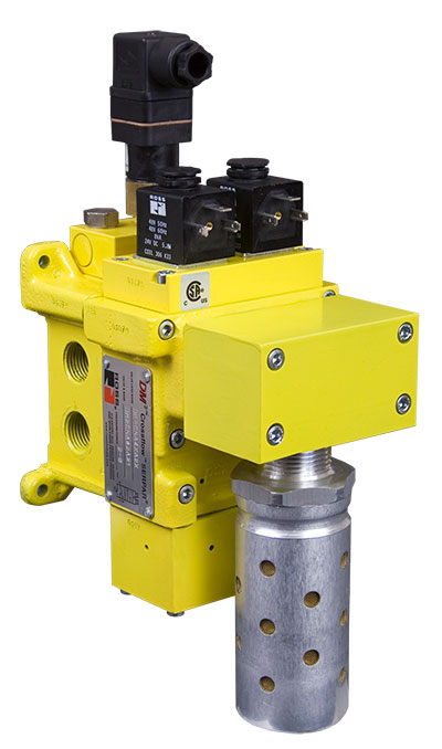
The block-and-bleed concept is so effective that various manufacturers such as SMC and Ross Controls make pneumatic safety valves that practice the concept as a specialty. The Ross Controls DM² Series valve (figure 1) employs multiple features to prevent energy from reaching a downstream actuator either intentionally or accidentally.
The valve block is essentially a 3-way, 2-position normally closed valve that blocks primary inlet pressure (either from the main receiver or a subcircuit at the machine) from reaching downstream, while keeping that downstream pressure vented to atmosphere. Mounting this valve at the supply of air to a machine, zone, or cell will provide a control reliable method of block and bleed.
The valve assembly consists of nearly a dozen internal valve components but can be best described as two pilot-operated 3-way, 2-position normally closed valves but with a crossflow arrangement. This means the supply to outlet paths are in series but outlet to exhaust paths are in parallel. Because of this arrangement, they must both be activated to allow flow from the inlet to outlet. If one valve or other fails to shift, no flow can occur. Control power is required for both solenoid valves simultaneously or the valve faults and must be reset.
Should only one of the two valves shift, the air is vented to the atmosphere, providing an audible signal that there is a problem. Until the valve is reset the assembly remains in safe mode while air is vented to atmosphere. Only when power is removed from the active coils can the manual reset be activated to allow the valve to function once again.
An additional feature of the safety valve is its ability to prevent activation when it senses low inlet energy from either low flow or pressure. When the incoming pressure is not high enough while the valve is energized the valve will fault but it cannot be reset until pressure is restored and the main coil signals removed. This is a safety function that ensures that only actuating the main coils can cause air to be supplied to the machine.
More simply, but no less important, are pneumatic lockout valves, such as the SMC VHS series in Figure 2. This is referred to as a pressure relief valve, but it’s essentially a 3-way, 2-position valve that manually vents downstream air to atmosphere. It provides a similar block and bleed function as the Ross DM², but obviously with less complexity.
A 3/2 safety valve is often used for maintenance purposes to prevent accidental machine operation when a technician is servicing the machine. Once the machine is shut down and ready for service, the technician rotates the knob to block incoming air supply, but also direct any or all downstream air out the bottom exhaust port. This ensures no residual pressure is capable of accidentally powering downstream actuators.
To guarantee technicians are protected during servicing, the valve is constructed with locking holes, allowing them to “lockout” the valve with their own padlock, to which they hold the only key. This practice is common with electrical panels but is becoming more popular as people realize the potential for harm with compressed air.
The safety valve can be installed at every airline drop, at machine FRLs or even at receiver outlets, should safety be the top concern. With ports up to 1 in. diameter, a CV over 8 provides more than 60 scfm – serious flow for the majority of applications.
The potential for injury exists in nearly every pneumatic machine, so safety must be taken seriously to prevent harm. Intelligent design must apply not only to cycle times and efficiency but also to the safe control of all functions. To this end, safety valves are absolutely essential.

An OSHA COMPRESSED AIR SAFETY SHUT-OFF VALVES should be placed immediately after the air control shut off valve and before the hose on a compressor, and after each discharge port that a hose is connected to.
Before starting the compressor the air control valve should be closed completely. When the compressor unloads, open the air shut off control valve very slowly. Full port ball valves tend to work better than gate or butterfly type valves.
The air shut off control valve must be fully open for the OSHA COMPRESSED AIR SAFETY SHUT-OFF VALVES to work. Some portable air compressor manufacturers recommend start-up with the air control valve slightly open. In this case you may have to close the valve and reopen it slowly to the full open position, or wait for the safety shut-off valve to reset itself.
If the OSHA COMPRESSED AIR SAFETY SHUT-OFF VALVES fails to operate despite meeting all condi-tions, check the hose line for obstructions or a hose mender restricting normal air flow.
• Turn on air supply slowly (to avoid tripping OSHA safety valve). Prior to fully reaching operation conditions, the OSHA COMPRESSED AIR SAFETY SHUT-OFF VALVES should suddenly activate and stop air flow.
• If the OSHA COMPRESSED AIR SAFETY SHUT-OFF VALVE is not activated the unit should be disconnected and the lower flow range OSHA COMPRESSED AIR SAFETY SHUT-OFF VALVES should be used. This means you need to use a different valve with a lower scfm range.
• At temperatures below 40°F ensure that OSHA COMPRESSED AIR SAFETY SHUT-OFF VALVES are not subject to icy conditions which may prevent proper functioning.

The primary purpose of a safety valve is to protect life, property and the environment. Safety valves are designed to open and release excess pressure from vessels or equipment and then close again.
The function of safety valves differs depending on the load or main type of the valve. The main types of safety valves are spring-loaded, weight-loaded and controlled safety valves.
Regardless of the type or load, safety valves are set to a specific set pressure at which the medium is discharged in a controlled manner, thus preventing overpressure of the equipment. In dependence of several parameters such as the contained medium, the set pressure is individual for each safety application.

Swissfluid SIV Inline Sampling Valves are installed directly in the pipeline or in a bypass piping system. Collecting a liquid sample with our cavity-free design results in a representative sample taken directly from the media flowing through the pipeline.
In connection with a closed Piston Injector also gases can be sampled besides liquids, without coming in contact with the atmosphere or with the operator. Our sampling valves and –systems are the preferred choice for applications in the chemical, pharmaceutical and refining industries, and are suitable for piping systems with flange connections per ASME B16.5 or DIN standard EN 1092, with face-to-face dimensions per ASME B16.10 or EN 558-1, range 1. Compact wafer connections, typically with a face-to-face length of 62mm (2.44in), are also available. Our SIV Sampling valves are designed for ANSI 150lbs, 300lbs and 600lbs systems, or in accordance with DIN PN16/40/64.
OPEN sampling from valves, container, reactors, etc. in the open position, into vessels without technical safety measures, or CLOSED sampling, where the product is taken from a closed system, without exposure to the person taking the sample or the atmosphere.
Sampling Valve bodies and spindles are available unlined from 1.4408 / 1.4404 stainless steel, or fully lined with PFA or PFA-AS (anti-static) in order to protect against highly corrosive or aggressive media. For ultimate corrosion protection, our SIV Sampling Valves are also available in exotic metals such as Titanium, Inconel or Hastelloy.
We offer our Sampling Ball Valve with CF-8M SS body (AISI 316) fluorothermoplastic-lined, or in an unlined version using the same body material. This volume-specific sampler draws a pre-determined volume – including minimal sample sizes - from horizontal and vertical piping systems. The collected sample and the main line are not connected after sampling, eliminating any system pressure being transferred, which also allows vacuum sampling. Full-port construction and close attachment of the sampling unit eliminate any dead space, which allows easy cleaning and purging of the piping system. Thanks to the large sample opening very high as well as very low viscosity samples can be taken.
This easy to operate Inline Sampling Ball Valve is suitable for clear, liquid media, within operating conditions of -40°F – 400°F and pressures up to 232psi.
Optional equipment to satisfy specific customer requirements include heating jackets, butt-weld ends or clamp connections. In order to create hermetically sealed sampling, we also offer safety cabinets, needle adapters and activated carbon filters.
As one of the leading manufacturers of cavity free plug valves and special valves, AZ supplies to production plants in the chemical, petrochemical, pharmaceutical, paper, food industries as well as for nuclear power plants and many other areas. Special valves for highest demands in areas with high operating pressures and aggressive, toxic or abrasive media are designed and developed together with our customers. In the 50 years of the company’s existence, AZ has continuously developed to meet the increasing requirements of customers active around the world and today AZ manufactures internationally on four continents.
A safety valve must always be sized and able to vent any source of steam so that the pressure within the protected apparatus cannot exceed the maximum allowable accumulated pressure (MAAP). This not only means that the valve has to be positioned correctly, but that it is also correctly set. The safety valve must then also be sized correctly, enabling it to pass the required amount of steam at the required pressure under all possible fault conditions.
Once the type of safety valve has been established, along with its set pressure and its position in the system, it is necessary to calculate the required discharge capacity of the valve. Once this is known, the required orifice area and nominal size can be determined using the manufacturer’s specifications.
In order to establish the maximum capacity required, the potential flow through all the relevant branches, upstream of the valve, need to be considered.
In applications where there is more than one possible flow path, the sizing of the safety valve becomes more complicated, as there may be a number of alternative methods of determining its size. Where more than one potential flow path exists, the following alternatives should be considered:
This choice is determined by the risk of two or more devices failing simultaneously. If there is the slightest chance that this may occur, the valve must be sized to allow the combined flows of the failed devices to be discharged. However, where the risk is negligible, cost advantages may dictate that the valve should only be sized on the highest fault flow. The choice of method ultimately lies with the company responsible for insuring the plant.
For example, consider the pressure vessel and automatic pump-trap (APT) system as shown in Figure 9.4.1. The unlikely situation is that both the APT and pressure reducing valve (PRV ‘A’) could fail simultaneously. The discharge capacity of safety valve ‘A’ would either be the fault load of the largest PRV, or alternatively, the combined fault load of both the APT and PRV ‘A’.
This document recommends that where multiple flow paths exist, any relevant safety valve should, at all times, be sized on the possibility that relevant upstream pressure control valves may fail simultaneously.
The supply pressure of this system (Figure 9.4.2) is limited by an upstream safety valve with a set pressure of 11.6 bar g. The fault flow through the PRV can be determined using the steam mass flow equation (Equation 3.21.2):
Once the fault load has been determined, it is usually sufficient to size the safety valve using the manufacturer’s capacity charts. A typical example of a capacity chart is shown in Figure 9.4.3. By knowing the required set pressure and discharge capacity, it is possible to select a suitable nominal size. In this example, the set pressure is 4 bar g and the fault flow is 953 kg/h. A DN32/50 safety valve is required with a capacity of 1 284 kg/h.
Coefficients of discharge are specific to any particular safety valve range and will be approved by the manufacturer. If the valve is independently approved, it is given a ‘certified coefficient of discharge’.
This figure is often derated by further multiplying it by a safety factor 0.9, to give a derated coefficient of discharge. Derated coefficient of discharge is termed Kdr= Kd x 0.9
Critical and sub-critical flow - the flow of gas or vapour through an orifice, such as the flow area of a safety valve, increases as the downstream pressure is decreased. This holds true until the critical pressure is reached, and critical flow is achieved. At this point, any further decrease in the downstream pressure will not result in any further increase in flow.
A relationship (called the critical pressure ratio) exists between the critical pressure and the actual relieving pressure, and, for gases flowing through safety valves, is shown by Equation 9.4.2.
Overpressure - Before sizing, the design overpressure of the valve must be established. It is not permitted to calculate the capacity of the valve at a lower overpressure than that at which the coefficient of discharge was established. It is however, permitted to use a higher overpressure (see Table 9.2.1, Module 9.2, for typical overpressure values). For DIN type full lift (Vollhub) valves, the design lift must be achieved at 5% overpressure, but for sizing purposes, an overpressure value of 10% may be used.
For liquid applications, the overpressure is 10% according to AD-Merkblatt A2, DIN 3320, TRD 421 and ASME, but for non-certified ASME valves, it is quite common for a figure of 25% to be used.
Two-phase flow - When sizing safety valves for boiling liquids (e.g. hot water) consideration must be given to vaporisation (flashing) during discharge. It is assumed that the medium is in liquid state when the safety valve is closed and that, when the safety valve opens, part of the liquid vaporises due to the drop in pressure through the safety valve. The resulting flow is referred to as two-phase flow.
The required flow area has to be calculated for the liquid and vapour components of the discharged fluid. The sum of these two areas is then used to select the appropriate orifice size from the chosen valve range. (see Example 9.4.3)
In order to ensure that the maximum allowable accumulation pressure of any system or apparatus protected by a safety valve is never exceeded, careful consideration of the safety valve’s position in the system has to be made. As there is such a wide range of applications, there is no absolute rule as to where the valve should be positioned and therefore, every application needs to be treated separately.
A common steam application for a safety valve is to protect process equipment supplied from a pressure reducing station. Two possible arrangements are shown in Figure 9.3.3.
The safety valve can be fitted within the pressure reducing station itself, that is, before the downstream stop valve, as in Figure 9.3.3 (a), or further downstream, nearer the apparatus as in Figure 9.3.3 (b). Fitting the safety valve before the downstream stop valve has the following advantages:
• The safety valve can be tested in-line by shutting down the downstream stop valve without the chance of downstream apparatus being over pressurised, should the safety valve fail under test.
• When setting the PRV under no-load conditions, the operation of the safety valve can be observed, as this condition is most likely to cause ‘simmer’. If this should occur, the PRV pressure can be adjusted to below the safety valve reseat pressure.
Indeed, a separate safety valve may have to be fitted on the inlet to each downstream piece of apparatus, when the PRV supplies several such pieces of apparatus.
• If supplying one piece of apparatus, which has a MAWP pressure less than the PRV supply pressure, the apparatus must be fitted with a safety valve, preferably close-coupled to its steam inlet connection.
• If a PRV is supplying more than one apparatus and the MAWP of any item is less than the PRV supply pressure, either the PRV station must be fitted with a safety valve set at the lowest possible MAWP of the connected apparatus, or each item of affected apparatus must be fitted with a safety valve.
• The safety valve must be located so that the pressure cannot accumulate in the apparatus viaanother route, for example, from a separate steam line or a bypass line.
It could be argued that every installation deserves special consideration when it comes to safety, but the following applications and situations are a little unusual and worth considering:
• Fire - Any pressure vessel should be protected from overpressure in the event of fire. Although a safety valve mounted for operational protection may also offer protection under fire conditions,such cases require special consideration, which is beyond the scope of this text.
• Exothermic applications - These must be fitted with a safety valve close-coupled to the apparatus steam inlet or the body direct. No alternative applies.
• Safety valves used as warning devices - Sometimes, safety valves are fitted to systems as warning devices. They are not required to relieve fault loads but to warn of pressures increasing above normal working pressures for operational reasons only. In these instances, safety valves are set at the warning pressure and only need to be of minimum size. If there is any danger of systems fitted with such a safety valve exceeding their maximum allowable working pressure, they must be protected by additional safety valves in the usual way.
In order to illustrate the importance of the positioning of a safety valve, consider an automatic pump trap (see Block 14) used to remove condensate from a heating vessel. The automatic pump trap (APT), incorporates a mechanical type pump, which uses the motive force of steam to pump the condensate through the return system. The position of the safety valve will depend on the MAWP of the APT and its required motive inlet pressure.
This arrangement is suitable if the pump-trap motive pressure is less than 1.6 bar g (safety valve set pressure of 2 bar g less 0.3 bar blowdown and a 0.1 bar shut-off margin). Since the MAWP of both the APT and the vessel are greater than the safety valve set pressure, a single safety valve would provide suitable protection for the system.
Here, two separate PRV stations are used each with its own safety valve. If the APT internals failed and steam at 4 bar g passed through the APT and into the vessel, safety valve ‘A’ would relieve this pressure and protect the vessel. Safety valve ‘B’ would not lift as the pressure in the APT is still acceptable and below its set pressure.
It should be noted that safety valve ‘A’ is positioned on the downstream side of the temperature control valve; this is done for both safety and operational reasons:
Operation - There is less chance of safety valve ‘A’ simmering during operation in this position,as the pressure is typically lower after the control valve than before it.
Also, note that if the MAWP of the pump-trap were greater than the pressure upstream of PRV ‘A’, it would be permissible to omit safety valve ‘B’ from the system, but safety valve ‘A’ must be sized to take into account the total fault flow through PRV ‘B’ as well as through PRV ‘A’.
A pharmaceutical factory has twelve jacketed pans on the same production floor, all rated with the same MAWP. Where would the safety valve be positioned?
One solution would be to install a safety valve on the inlet to each pan (Figure 9.3.6). In this instance, each safety valve would have to be sized to pass the entire load, in case the PRV failed open whilst the other eleven pans were shut down.
If additional apparatus with a lower MAWP than the pans (for example, a shell and tube heat exchanger) were to be included in the system, it would be necessary to fit an additional safety valve. This safety valve would be set to an appropriate lower set pressure and sized to pass the fault flow through the temperature control valve (see Figure 9.3.8).

Hydraulic and pneumatic systems must regulate air or liquid pressure according to a constant pressure threshold. If the pressure exceeds the set level, it can damage equipment and create a safety hazard for workers. Pressure relief valves regulate pressure levels to prevent these dangers.
Pressure relief valves (PRVs), or back pressure regulators, reduce system pressure when it exceeds a maximum threshold. PRVs can also reduce pressure peaks that could damage equipment elsewhere in the facility. The main components of a pressure relief valve are:
When the pressure in the hose or pipe exceeds the pressure limit, will push against the diaphragm, compress the spring and open the valve. The valve opens and closes to maintain the specified pressure level. When the pressure dips below the accepted threshold, the valve closes. With adjustable PRVs, operators can adjust the spring mechanism to collapse under a higher or lower amount of pressure.
Enhances safety: PRVs were invented as a result of boilers exploding when they were not properly monitored. Thus, they are an easy and effective way to keep your system safe.
Increases efficiency: Relief valves automatically reclose when the pressure lowers to the set level, preventing excess loss of expensive gases from the system.
Materials: Most valves are made of plastic, brass, aluminum, or stainless steel. Weigh each material’s compatibility, advantages, and disadvantages relative to your system’s needs.
Operating temperature: Make sure the valve you choose can handle the expected operating temperature of your application, as the temperature can affect flow capacity and the responsiveness of the spring mechanism.
Air Logic designs and manufactures industrial pneumatic and vacuum control equipment, including preset and adjustable relief valves for medical and other applications. Our adjustable relief valves can be equipped with straight or barbed fittings. Single barbed models work best with exhaust ports that do not need a barb.
We also offer preset options, which we produce by presetting an adjustable valve at the desired pressure level. We test the valve for effectiveness before shipping it to you. Our ISO 9001:2015 certification ensures high-quality, reliable products with every delivery.
Try before you buy – what’s better than free? Take advantage of a new online offer from Rexroth Pneumatics for a free sample of the Series QR1 pneumatic push-in fittings.
Series QR1 fittings from Rexroth Pneumatics are a light-weight, polymer design suitable for all Rexroth pneumatic products such as valves and cylinders. The push-to-connect style fittings have an oval release ring with an enlarged surface area for quick, easy release of pneumatic tubing. Other features include: standard nickel-plated brass threads, inch or metric (ISO G) versions, Teflon thread sealant standard on NPT versions and a stainless steel internal locking ring.
The comprehensive line of QR1 fittings consist of the Mini design for plastic tubing ODs of 1/8” to 1/4” and 3-6 mm, and the Standard design for tubingODs of 5/32” to 1/2″ and 4-16 mm. Products such as check, ball and flow control valves are also included in the range of function fittings.
The Unique Sampling Valve is designed for sterilization before and after each sample. The valve body and connecting pieces are made from one piece of material to avoid cracks and welding pores.Working Principle
Sterilizing: when the valve closes, the channel between the valve ports opens for sterilization. If using steam, a small pressure relief valve (optional) on the outlet is recommended.
The valve consists of three parts: a valve body, an actuator, and a membrane seal. The rubber membrane seal is placed on the stem of the actuator and works as a stretchable plug. The valve bodies and actuators are interchangeable.

V, VB, and VL series 2-, 3-, and 5-valve instrument manifolds; VE series 2-, 3-, and 5-valve direct-mount manifolds; 2-valve remote-mount manifolds;Mod 85 modular instrumentation systems
Packless valves with all-metal seal to atmosphere; Working pressures up to 3500 psig (241 bar); Temperatures up to 400°F (204°C); VCR® face seal fitting, Swagelok® tube fitting, and weld end connections
Features: Working pressures up to 3000 psig (206 bar); Temperatures up to 400°F (204°C) with standard PTFE packing, up to 600°F (315°C) with optional Grafoil® packing; Straight and angle-pattern valves
Swagelok thermal-immersion diaphragm valves offer high-speed actuation and are designed for optimum performance at 220 degrees C (428 degrees F) for high-temperature processes.
Features: Working pressures up to 6000 psig (413 bar); Flow coefficients (Cv) from 4.0 to 13.8; Fractional and metric Swagelok tube fittings; ISO and NPT pipe end connections available; 316 stainless steel body and end connections; Manual and pneumatic actuation
Features: Suitable for ultrahigh-purity applications;316L VIM-VAR stainless steel body; Low-pressure and high-pressure models; VCR®, tube butt weld, and modular surface-mount end connections; Manual or pneumatic actuation
ALD 3, 6, and 7 Diaphragm Valves and ALD20 Bellows: Ultrahigh cycle life, high-speed actuation; Up to 392°F (200°C) w thermal actuators; Electronic actuator position-sensing; ultrahigh-purity applications; High flow capacity, PFA seat, Normally closed pneumatic actuation, Alloy 22 available
Features: 316L stainless steel and modified PTFE wetted parts; Variety of compact multivalve, multiport configurations; Choice of sanitary clamp and butt weld end connections; Choice of pneumatic or manual actuators in plastic or aluminum; Five sizes from 1/2 to 2 in.
Features: Pneumatic and quarter-turn manual 2-way and 3-way models; pneumatic and manual models with adjustable flow and bypass features; DuPont® Teflon® modified PTFE wetted parts and polypropylene actuator; Meet SEMI Standard F57-0301 for ultrahigh-purity system components; Fine thread flare and Nippon Pillar® Super 300 end connections standard; space saver and other end connections available; Custom manifolds and subassemblies available
Features: All-welded design provides reliable containment of system fluid; Forward flow starts at less than 2 psig (0.14 bar) pressure differential; Valve closes with less than 2 psig (0.14 bar) back pressure; 316L SS body offers enhanced material purity
Features: stainless steel, carbon steel, and duplex stainless steel materials; pressure ratings in accordance with ASME B16.5; flanged connections compatible with ASME B16.5; ball valve bore sizes from 3/8 to 2 in. (9.5 to 50.8 mm)
Features: Packless valves with all-metal seal to atmosphere; Working pressures up to 500 psig (34.4 bar); Temperatures up to 200°F (93°); 1/4 to 1/2 in. and 6 to 12 mm end connections
Features: The Swagelok® compact gauge valve provides fast, convenient installation and installation and gauge maintenance in a lightweight package and smaller footprint than conventional assemblies.
Features: Compact, packless valve switches flow from one line to another. Torlon® stem guide ensures proper alignment for consistent shutoff performance. Manual and spring-return and double-acting pneumatic actuators are available. End connections include 1/4 in. Swagelok® VCR® metal gasket face seal fittings and 1/4 in. Swagelok tube fittings.
Features: 316 stainless steel materials; Union-bonnet construction for safety; Grafoil® packing for high-temperature performance; Swagelok® tube fitting, female NPT, and tube or pipe socket weld end connections
Features: Limits access to manually actuated valves;Lockout accessory enables compliance with OSHA Lockout/Tagout, Standard 29 CFR Part 1910.147, Control of Hazardous Energy Bright safety orange color promotes high visibility. Other colors are available.
GB series ball valves; Working pressures up to 6250 psig (430 bar) with temperatures from –40 to 248˚F (–40 to 120˚C); Swagelok® tube fitting end connections, 3/8 in. to 1 in. female pipe, and fractional or metric (12 mm to 25 mm); Corrosion-resistant body materials: 316/316L, Alloy 2507, 6-Moly, Alloy 625, Alloy 825, Alloy C-276; Optional API 607 for fire-safe applications and NACE MR0175/ISO 15156 for sour gas
Features: 1/8 to 2 in. and 6 to 25 mm sizes; Stainless steel, carbon steel, brass, and special alloy materials; On-off (2-way) and switching (3-way) valves; Compensating seat design; Live-loaded, two-piece stem packing
Features: 3/8 to 1 in. sizes; alloy 625, alloy 825, Alloy 2507, and alloy 6-moly materials; On-off (2-way) valves; Compensating seat design; Live-loaded, two-piece stem packing
Bleed Valves: Working pressures up to 10 000 psig (689 bar); Temperatures up to 850°F (454°C); 316 stainless steel, carbon steel, alloy 400, or alloy C-276 materials. Purge Valves: Working pressures up to 4000 psig (275 bar); Temperatures up to 600°F (315°C); 316 stainless steel, brass, or carbon steel materials
Features: 1.125 in. C-seal and W-seal designs; Available in two- and three-port configurations; Compact pneumatic and manual actuators; Pneumatic actuator indicator ball: red for normally closed, green for normally open; Fixed orientation of actuator to body for consistency of installation; Corner chamfers on outlet side of body for visual indication of flow direction
Features: Rack and pinion pneumatic actuators, solenoid valves, and limit switches; ISO 5211-compliant pneumatic actuators, solenoid valves, limit switches, and position sensors; Complete actuated assemblies and kits for field assembly available
Features: Alloy 625, alloy 825, and Alloy 2507 super duplex stainless steel materials; Available for CH4 adn Ch8 series check valves; Working pressures up to 6 000 psig (413 bar); 1/4 to 1/2 in. Swagelok tube fitting or NPT end connections;

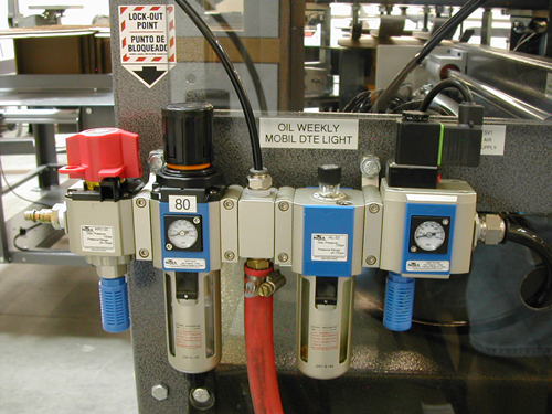
Compressed air pneumatic systems require methods of safe and precise control of the actuators unique to their accoutrement. Although the medium is fluid, just as hydraulic or process water systems, the execution of control is different in many ways than with a liquid. What is shared in the conduction of any fluid power medium is the need for valves to control force, velocity and direction of movement.
Pressure relief valves will control pressure at their inlet port by exhausting pressure to atmosphere. Relief valves are typically used only in receivers or air storage devices, such as accumulators, as a means to prevent excessive pressurization. As such, relief valves are often called safety valves and are not typically appropriate for use anywhere but the air preparation stage.
Pressure regulators in pneumatic systems limit pressure downstream of the unit by blocking pressure upstream at the inlet. Regulators are used in the air preparation stage, as well as in control of cylinders and motors. The letter R in the acronym FRL stands for regulator, which is installed downstream of the receiver tank, but before the circuit they are regulating pressure for.
Pressure regulators can also be used to control pressure for individual actuators, such as an inline regulator or work-port mounted regulator. These are typically quite small and included with reverse flow check valves, as would be required for double acting function of a cylinder, for example. Further still, differential pressure regulators are offered by some manufacturers, to maintain a set pressure differential between the two ports, rather than just maintaining downstream pressure. It should be noted that all pressure regulators are adjustable, most often with screws or knobs.
Also common in pneumatic systems are valves to control flow. There are fewer available types of flow valves compared to pressure or directional valves, but most circuits apply them to make for easy adjustment to cylinder or motor velocity. Controlling velocity in pneumatic systems is more complex than in a hydraulic system, because pressure differential between the work ports of a cylinder plays a larger part.
Flow control valves for pneumatic systems are quite simple, usually available in two configurations used in two different ways. One configuration is merely a variable restriction, with a screw or knob adjustment to open and close a variable orifice, which is also often referred to as a needle or choke valve. The other type introduces a check valve, which allows free flow in one direction, and restriction in the opposing direction. For whatever reason, this valve has hijacked the name flow control all for itself.
Flow control valves are applied in two different ways; meter in or meter out. Meter in is the method of controlling the rate of airflow as it enters a motor or cylinder. When metering in, a cylinder will move rapidly with high force and efficiency, but the motion of the piston is prone to spongy and unpredictable movement. When metering out, the cylinder velocity is more stable and repeatable, but efficiency and dynamic force are lost to the energy required to push past the flow control. Regardless, most pneumatic applications operate using meter out flow controls, because the disadvantages are easy to overcome by increasing upstream pressure.
A method of increasing cylinder velocity, typically for double acting or spring-return cylinder retraction functions, is to add a quick exhaust valve to the cap side work port. Because cylinders retract faster than they extend as a result of differential air volumes, it is harder to evacuate the cap side air volume without oversized valves or plumbing. A quick exhaust valve vents directly to air from the cap side work port, and massively reduces the backpressure created upon retraction, permitting very rapid piston velocity.
Pneumatic directional valves are available in many sizes, styles and configurations. At the basic end of the spectrum is the simple check valve, which allows free flow in one direction and prevents flow in the reverse direction. These can be installed anywhere from right after the receiver to within a flow control valve itself.
As directional valves grow in complexity, they are specified under a general naming practice related to the number of positional envelopes of the valve and the number of work ports in the valve, and specifically in the order described. For example, if it has five ports, port 1 will be for pressure inlet, ports 2 and 4 for work ports, and 3 and 5 for the exhaust ports. A valve with three positions will have a neutral condition, extend condition and retract condition. Putting it all together, this describes a five-way, three position valve, also referred to as a 5/3 valve. The common configurations seen in pneumatics are 5/3, 5/2, 4/2, 3/2 and sometimes 2/2 valves.
Also part of the description of a directional valve is its method of both operation and positioning. The valve operator is the mechanism providing the force to shift the valve between its positions. The operator can be a manual lever, electric solenoid, an air pilot, or cam mechanism, to name a few. Some valves are a combination of these, such as a solenoid pilot valve, which is a tiny valve providing pilot energy to move the mainstage valve. Positioning of any valve is achieved by either a spring, such as with a 5/2 spring-offset valve, or with detents in 5/2 detented valves.
A 5/2 spring-offset valve will return to its starting position when energy is removed from its operator, like de-energizing the coil, or removing pilot pressure. A 5/2 detented valve will stay in the position it was last activated to until the operator switches it again.
Pneumatic valves are manufactured in various incarnations. Poppet valves are simple, using a spring to push a face of the poppet down on its seat. Construction can be metal-to-metal, rubber-to-metal or even with diaphragms. Poppet valves can often flow in one direction, just as a check valve, but need to be energized to flow in reverse. They are limited to twoor three-way port configurations, although they can mimic four- or five-way valves when used in parallel. They offer typically high flow conductance for their size, and are generally very resistant to contamination.
Spool valves use a notched metal cylinder that slides within a precisely machined body, drilled with three to five ports, or even seven ports if the valve is pilot operated. Low-end valves consist of only a spool and body, and are prone to internal leakage. Better valves use seals in the body or spool to prevent leakage between ports. High-end spool valves are constructed with precision, often requiring fine lapping procedures during manufacturing, and with their tight tolerances, often require few seals, improving reliability and longevity. Other forms of high-end valves use a sliding block of metal or ceramic, which is not only efficient, but also extremely resistant to contamination, making them great for dirty environments.
Pneumatic directional valves come in both standard and non-standard mounting configurations. The non-standard valve is constructed at the whim of the manufacturer, with port layout, operator style and mounting options unique to their product. They can be inline, subplate mounted or sectional stacks mounted in a row. Because each manufacturer does mounting differently, it is best to research the product appropriate for your application.
Luckily, most manufacturers have lines of standardized valves suiting one or more specification, such as ISO 5599-1, with its staggered oval ports; this means one manufacturer"s valve will fit the subplate or manifold of another manufacturer"s. Port and electrical connections are standardized with most valves as well. NPT ports are common, but many new valves come with push lock fittings on the subplate itself. Electrical connectors for standardized valves are frequently DIN, mini-DIN or with field bus connection, making the operation of a dozen valves as easy as one connector.


 8613371530291