
safety valve air brakes free sample
As well, the compressor in the system is capable of pumping air pressure to 500 psi (3450kPa), which poses danger to both the driver and others around the vehicle.
The driver of a commercial vehicle must know that the safety valve makes the sound of a machine gun when it releases excess air pressure from the system.

Some browsers have a " Do Not Track" feature that lets you tell websites that you do not want to have your online activities tracked. These features are not yet uniform. Although we do not at this time honor “ Do Not Track” signals from a web site browser, we offer you a choice about whether to accept cookies from our website, and you may refuse, or later delete, cookies. Please refer to your browser’s Help instructions to learn more about cookies and other technologies and how to manage their use. If you elect to refuse or delete cookies, you will need to repeat this process each time you use a different computer or change browsers. If you choose to decline cookies, some of your online functionality may be impaired.
In addition, we may disclose information collected from and about you as follows: (1) you expressly request or authorize us to do so ; (2) we believe the information is needed to comply with the law (for example, to comply with a search warrant, subpoena or court order), respond to a government request, enforce an agreement we have with you, or to protect our rights, property or safety, or the rights, property or safety of our employees or others ; (3) the information is provided to our agents, third parties or service providers who perform functions on our behalf ; (4) to address emergencies or acts of God ; (5) in anticipation of and in the course of an actual or potential sale, reorganization, consolidation, merger, or amalgamation of all or part of our business or operations in which case your information may be provided to the purchaser or resulting entity ; or (6) to address disputes, claims, or to persons holding a legal or beneficial interest.
Under California Civil Code Section 1789.3, California users of the Services are entitled to the following specific consumer rights notice: The Complaint Assistance Unit of the Division of Consumer Services of the California Department of Consumer Affairs may be contacted in writing at 1625 North Market Blvd., Suite N 112, Sacramento CA 95834, or by telephone at (916) 445-1254 or (800) 952-5210.

The safety relief valve in an air brake system releases air if necessary to prevent pressure in the system from becoming too high. If the valve starts releasing air, there is something wrong. Have a mechanic fix the problem.
1. When you are testing the air leakage rate, the air loss rate after the initial pressure drop should be less than __________ psi in one minute for combination vehicles.A. two
If you drive a vehicle with air brakes, you should conduct a final air brake check instead of a hydraulic brake check during step seven of the Seven-step Inspection Method. Test the air leakage rate. With a fully-charged air system (typically 125 psi), turn off the engine, release the parking brake, and time the air pressure drop. The loss rate should be less than two psi in one minute for single vehicles and less than three psi in one minute for combination vehicles. Then apply 90 psi or more with the brake pedal. After the initial pressure drop, if the air pressure falls more than three psi in one minute for single vehicles (more than four psi for combination vehicles), the air loss rate is too much. Check for air leaks and fix the problem before driving the vehicle. Otherwise, you could lose your brakes while driving.
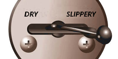
Some older vehicles (made before 1975) have a front brake limiting valve and a control in the cab. The control is usually marked "normal" and "slippery." When you put the control in the "slippery" position, the limiting valve cuts the "normal" air pressure to the front brakes by half. Limiting valves were used to reduce the chance of the front wheels skidding on slippery surfaces. However, they actually reduce the stopping power of the vehicle. Front wheel braking is good under all conditions. Tests have shown that front wheel skids from braking are not likely even on ice. Make sure the control is in the "normal" position to have normal stopping power. Many vehicles have automatic front wheel limiting valves. They reduce the air to the front brakes except when the brakes are put on very hard (60 psi or more application pressure). These valves cannot be controlled by the driver.
3. If there is an air leak in the system, a heavily loaded vehicle will take a long distance to stop because __________A. the spring brakes work on all axles.
If the low air pressure warning comes on, stop and safely park your vehicle as soon as possible. There might be an air leak in the system. Controlled braking is possible only while enough air remains in the air tanks. The spring brakes will come on when the air pressure drops into the range of 20 to 45 psi. A heavily loaded vehicle will take a long distance to stop because the spring brakes do not work on all axles. Lightly loaded vehicles or vehicles on slippery roads may skid out of control when the spring brakes come on. It is much safer to stop while there is enough air in the tanks to use the foot brakes.
In air-operated disc brakes, air pressure acts on a brake chamber and slack adjuster, like s-cam brakes. But instead of the s-cam, a "power screw" is used. The pressure of the brake chamber on the slack adjuster turns the power screw. The power screw clamps the disc or rotor between the brake lining pads of a caliper, similar to a large c-clamp. Disc brakes are less common than s-cam brakes.
When main air pressure is lost, the spring brakes come on. Some vehicles, such as buses, have a separate air tank which can be used to release the spring brakes. This is so you can move the vehicle in an emergency. One of the valves is a push-pull type and is used to put on the spring brakes for parking. The other valve is spring loaded in the "out" position. When you push the control in, air from the separate air tank releases the spring brakes so you can move. When you release the button, the spring brakes come on again. There is only enough air in the separate tank to do this a few times. Therefore, plan carefully when moving. Otherwise, you may be stopped in a dangerous location when the separate air supply runs out.

It’s impossible to fix something without understanding how it’s supposed to work. Brake system repair decisions can be difficult to make, and costly to execute, without a basic understanding of system components and their operation.
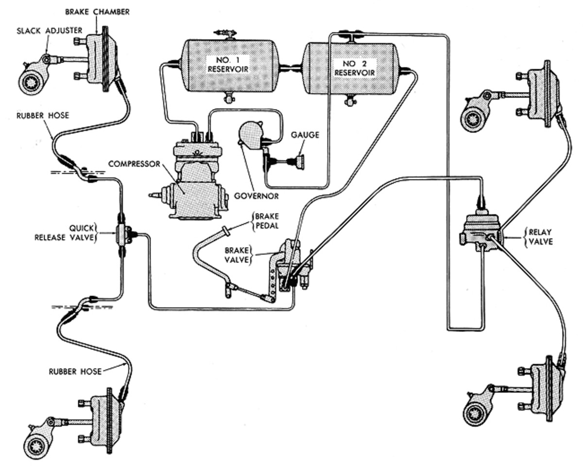
The following discussion details the operation of a typical S-cam air brake system on a single-axle tractor and trailer (see diagrams). Systems vary somewhat, depending on the manufacturer and on optional equipment and configuration, but all can be thought of as comprising three sub-systems.
The supply system, as the name implies, supplies pressurized air – the energy source for any air brake system. The key player in this sub-system is an engine-driven air compressor (1). A governor (2), which may be integrated with the compressor, controls the compressor’s output by unloading or cycling it. Pressure is generally maintained at 100 to 120 psi, and is monitored by the driver by means of dash-mounted pressure gauges (3). A low-pressure switch (4) senses system pressure and sends an electrical signal to a dash light or buzzer to alert the driver when air pressure falls below 60 psi.
Reservoirs, three per tractor and, usually, two per trailer, store the compressed air until it is needed to actuate the brakes. Check valves (5) prevent pressurized air in the primary and secondary reservoirs from passing back through the compressor while it is not running. A safety or “pop-off” valve (6) is usually installed in the reservoir closest to the compressor. In the event of over-pressurization, the safety valve allows air to escape, preventing damage to air lines, reservoirs and other components.
The reservoir closest to the compressor is often referred to as a wet tank, because that is where atmospheric moisture – the No. 1 enemy of air brake systems – condenses in the greatest quantities. Reservoirs are equipped with drain valves (7) so water can periodically be eliminated. These can be manually or automatically operated. Alcohol is sometimes introduced into air systems operating in cold climates to prevent water from freezing and plugging air lines.
An air dryer (8) is a device that condenses and eliminates most of the water from an air system. An air dryer is a canister that usually contains a bed of desiccant material. As air passes through, the material captures moisture and blow-by from the compressor.
The control system consists of a series of pneumatic valves that direct air and control pressure to appropriate components. Although discussed here individually, different valves are often combined in a common housing.
The main valve is the dual-control foot valve (9), so called because it is actually two valves that operate simultaneously, in response to input from the driver’s foot at the brake pedal.
Two valves are necessary because, after the wet tank output, the system splits into two separate brake circuits. Air downstream of the wet tank is divided between primary and secondary reservoirs. The split system ensures that, in the event of a failure, the entire system will not become inoperative, and the truck can be brought to a controlled stop.
When the brake pedal is depressed, air flows from the primary reservoir and through the primary portion of the dual-control foot valve to actuate the rear axle brakes. Meanwhile, air flows from the secondary reservoir, through the secondary portion of the dual-control foot valve, to actuate the front axle brakes. A two-way check valve (10) senses primary and secondary supply pressure, and allows the dominant pressure to actuate the trailer brakes. Primary air can also be manually supplied to the trailer by means of a hand valve, (11) usually located on or near the steering column.
Relay valves (13) are used on trailers and on the rear axles of long-wheel-based tractors to minimize delays of brake application due to length of plumbing. These valves are directly supplied with unmodulated air pressure, and use air from the dual-control foot valve or manual trailer valve as a signal to quickly direct air to the brakes they serve.
Relay valves come in a variety of “crack” pressures. Crack pressure is the air pressure value required at the input from the foot valve before the relay valve will send air pressure to the brakes controlled by that valve. Crack pressure is an important element of brake timing and balance, and is determined – axle by axle – by how heavily loaded the axle served by a valve is, how big its brakes are, and how aggressive the linings are on those brakes.
A valve that cracks at too low a pressure for a given axle can cause premature application, wheel lockup and trailer pushing, if the affected axle is on the tractor. Too high a crack pressure can cause delayed application, insufficient braking and trailer pushing, if the affected axle is on the trailer.
After a stop, when the driver lifts his foot from the brake pedal, a quick release valve (14) allows brake actuation air to be quickly exhausted near the brakes it serves, rather than having to travel back through the supply line, thus speeding brake release time.
Dash-mounted valves (15 and 16) control air pressure to the parking brakes. In most cases, these are spring brakes, so called because when no pressure is supplied, the brakes are applied by means of a spring. Air pressure, when applied, overcomes spring force and releases the brakes. More on that a little later.
A tractor protection valve (17) senses pressure in one or both lines that carry air to the trailer. These lines are connected to the trailer by means of quick-connect air fittings called gladhands. When there is no pressure in the line(s) – due to trailer breakaway or a gross air leak in the trailer circuit – the valve closes to maintain air pressure in the tractor circuit. In everyday use, the valve also works in conjunction with the dash-mounted trailer parking brake valve (16), to shut off air to the trailer circuit before disconnecting tractor from trailer.
The spring brake (or multi-function) valve (18) limits the air pressure used to keep the trailer parking brakes off and, by means of an integral check valve, isolates a failed reservoir, which would otherwise cause the parking brakes to be automatically applied.
Foundation brakes are where properly supplied and controlled air is used to stop a vehicle. When the brake pedal is depressed, air pressure is directed to brake chambers (19) at each wheel end. Brake chambers consist of a pressure housing, diaphragm and pushrod. As air pressure is exerted on the diaphragm, the pushrod on the other side of the diaphragm is extended. The force the pushrod exerts is the product of the amount of air pressure applied in psi, and the area of the diaphragm in square inches. For example, 60 psi, applied to a chamber with a 16-square-inch diaphragm would create a force at the pushrod of 960 pounds. A 60-psi application to a chamber with a 30-square-inch diaphragm would yield 1,800 pounds of pushrod force. Improperly matched brake chambers, therefore, can cause severe brake balance problems.
The shaft, in turn, is connected to an S-shaped cam between the brake shoes. As the shaft rotates, so does the cam. The brake shoes are forced apart and against the brake drum, creating the friction needed to slow the vehicle. The amount of friction produced is determined, in part, by the size of the brakes, the coefficient of friction (aggressiveness) of the brake lining material, and the mass and heat-rejection potential of the drum.
The slack adjuster is equipped with an adjusting mechanism to compensate for brake lining wear. If this were not so, the pushrod would be required to extend farther and farther as brake lining wear progressed. It wouldn’t take long before the pushrod would not be able to extend far enough to apply the brakes. Modern brake adjusters accomplish this automatically.
The brake adjuster’s length and the brake chamber’s size are two variables commonly altered to meet braking requirements. The product of these two values is expressed as the “AL factor.” This factor, when multiplied by 60 psi air pressure, is the industry standard for braking calculations.
In addition to applying the service brakes used in everyday driving, the brake chambers on the rear tractor axles and on the trailer axles apply the parking brakes. These brake chambers, (spring brakes), incorporate a second chamber, containing a second diaphragm and a powerful spring.
When the vehicle is in use, the dash-mounted parking brake valves are in the “run” (pushed-in) position. This supplies air pressure to the spring chamber, on the side of the diaphragm opposite the spring. Air pressure acting on the diaphragm compresses the spring, and the parking brakes are held off. This does not affect the operation of the service brakes.
When the vehicle is parked, the dash valves are pulled out. This exhausts spring brake hold-off air, allowing the spring to apply the parking brakes. In the event of a loss of system pressure, hold-off air pressure is overcome by the parking brake spring, and the brakes are automatically applied to provide emergency stopping.
Per federal regulations, the parking brakes must be able to hold a vehicle, loaded to its gross weight rating, stationary on a smooth, dry, concrete roadway, facing uphill or downhill, on a 20 percent grade.
We hope that this overview of air brake basics helped clarify your understanding and provide a grounding for dealing with more complex braking topics to be covered in future issues of CCJ.

This section tells you about air brakes. If you want to drive a truck, bus, or pull a trailer with air brakes, you need to read this section. If you want to pull a trailer with air brakes, you also need to read Section 6: Combination Vehicles in this handbook.
Air brakes use compressed air to make the brakes work. Air brakes are a good and safe way of stopping large and heavy vehicles, but the brakes must be well maintained and used properly.
CDL Air Brake Requirements. For CDL purposes, a vehicle’s air brake system must meet the above definition and contain the following, which will be checked during the vehicle inspection test:
If the vehicle you use for your road test does not have these components, your vehicle will not be considered as having an air brake system and you will have a “No Air Brakes” (“L”) restriction on your CDL.
A full service brake application must deliver to all brake chambers not less than 90 percent of the air reservoir pressure remaining with the brakes applied (CVC §26502).
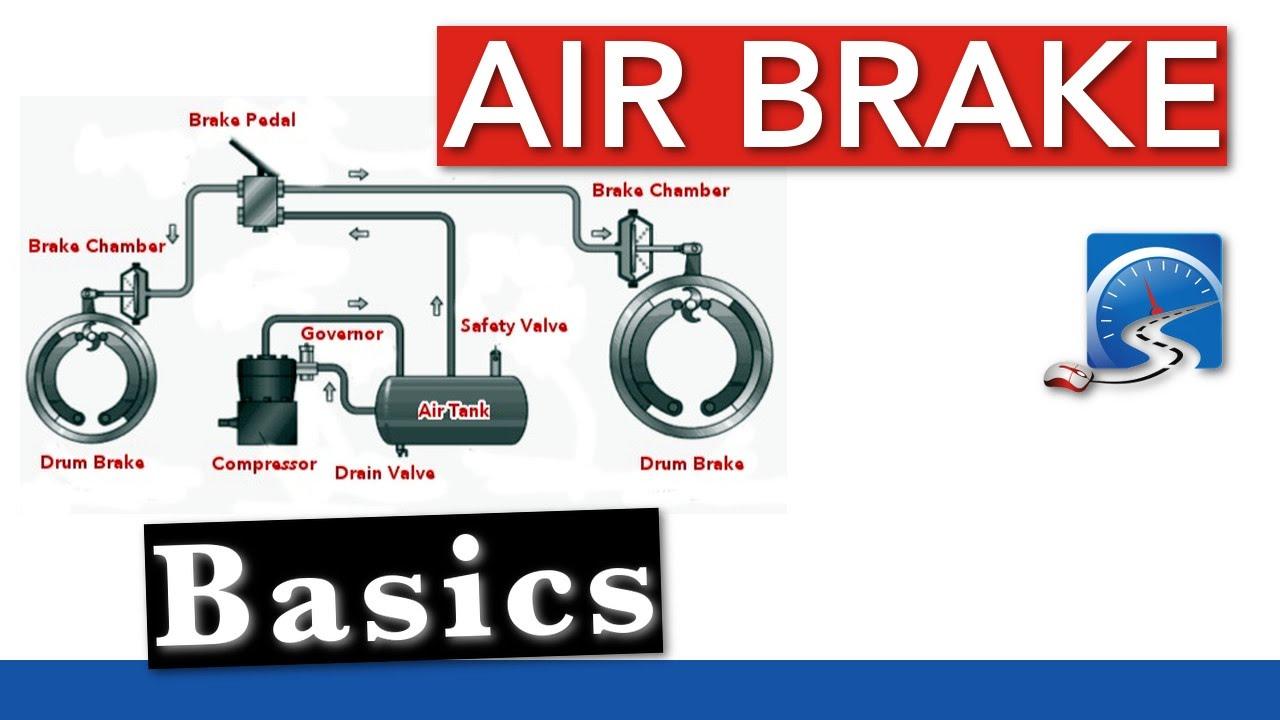
The air compressor pumps air into the air storage tanks (reservoirs). The air compressor is connected to the engine through gears or a v-belt. The compressor may be air cooled or cooled by the engine cooling system. It may have its own oil supply or be lubricated by engine oil. If the compressor has its own oil supply, check the oil level before driving.
The governor controls when the air compressor will pump air into the air storage tanks. When air tank pressure rises to the “cut-out” level (around 125 pounds per-square-inch or “psi”), the governor stops the compressor from pumping air. When the tank pressure falls to the “cut-in” pressure (around 100 psi), the governor allows the compressor to start pumping again.
Air storage tanks are used to hold compressed air. The number and size of air tanks varies among vehicles. The tanks will hold enough air to allow the brakes to be used several times, even if the compressor stops working.
Compressed air usually has some water and some compressor oil in it, which is bad for the air brake system. The water can freeze in cold weather and cause brake failure. The water and oil tend to collect in the bottom of the air tank. Be sure that you drain the air tanks completely. Each air tank is equipped with a drain valve in the bottom. There are 2 types:
Some air brake systems have an alcohol evaporator to put alcohol into the air system. This helps to reduce the risk of ice in air brake valves and other parts during cold weather. Ice inside the system can make the brakes stop working.
Check the alcohol container and fill up as necessary. (every day during cold weather). Daily air tank drainage is still needed to get rid of water and oil (unless the system has automatic drain valves).
A safety relief valve is installed in the first tank the air compressor pumps air to. The safety valve protects the tank and the rest of the system from too much pressure. The valve is usually set to open at 150 psi. If the safety valve releases air, something is wrong. Have the fault fixed by a mechanic.
You engage the brakes by pushing down the brake pedal (It is also called a foot valve or treadle valve). Pushing the pedal down harder applies more air pressure. Letting up on the brake pedal reduces the air pressure and releases the brakes. Releasing the brakes lets some compressed air go out of the system, so the air pressure in the tanks is reduced. It must be made up by the air compressor. Pressing and releasing the pedal unnecessarily can let air out faster than the compressor can replace it. If the pressure gets too low, the brakes will not work.
Brake Drums, Shoes, and Linings. Brake drums are located on each end of the vehicle’s axles. The wheels are bolted to the drums. The braking mechanism is inside the drum. To stop, the brake shoes and linings are pushed against the inside of the drum. This causes friction, which slows the vehicle (and creates heat). The heat a drum can take without damage depends on how hard and how long the brakes are used. Too much heat can make the brakes stop working.
S-cam Brakes. When you push the brake pedal, air is let into each brake chamber. Air pressure pushes the rod out, moving the slack adjuster, thus twisting the brake camshaft. This turns the S-cam (it is shaped like the letter “S”). The S-cam forces the brake shoes away from one another and presses them against the inside of the brake drum. When you release the brake pedal, the S-cam rotates back and a spring pulls the brake shoes away from the drum, letting the wheels roll freely again. See Figure 5.2.
One feature is a completely internal adjustment system which is designed to continually keep the brake in proper adjustment. S-cam brakes, on the other hand, require an external slack adjuster. The second feature is a unique cam design that applies the brake shoe. Unlike a standard drum brake that has either a single or double anchor-pin brake, the CamLaster slides the shoes down an inclined ramp on a cam to evenly contact the brake drum.
Wedge Brakes. In this type of brake, the brake chamber push rod pushes a wedge directly between the ends of 2 brake shoes. This shoves them apart and against the inside of the brake drum. Wedge brakes may have a single brake chamber or 2 brake chambers that push wedges in at both ends of the brake shoes. Wedge type brakes may be self-adjusting or may require manual adjustment.
Disc Brakes.In air-operated disc brakes, air pressure acts on a brake chamber and slack adjuster, like S-cam brakes. But instead of the S-cam, a “power screw” is used. The pressure of the brake chamber on the slack adjuster turns the power screw. The power screw clamps the disc or rotor between the brake lining pads of a caliper, similar to a large c-clamp.
All vehicles with air brakes have a pressure gauge connected to the air tank. If the vehicle has a dual air brake system, there will be a gauge for each half of the system (or a single gauge with two needles). Dual systems will be discussed later. These gauges tell you how much pressure is in the air tanks.
This gauge shows how much air pressure you are applying to the brakes. (This gauge is not on all vehicles.) Increasing application pressure to hold the same speed means the brakes are fading. You should slow down and use a lower gear. Brakes that are of adjustment, air leaks, or mechanical problems can also cause the need for increased pressure.
A low air pressure warning signal is required on vehicles with air brakes. A warning signal you can see must come on when the air pressure in the tanks falls between 55 and 75 psi (or 1/2 the compressor governor cutout pressure on older vehicles). The warning is usually a red light. A buzzer may also come on.
Drivers behind you must be warned when you put your brakes on. The air brake system does this with an electric switch that works by air pressure. The switch turns on the brake lights when you put on the air brakes.
Some vehicles made before 1975 have a front brake limiting valve and a control in the cab. The control is usually marked “normal” and “slippery.” When you put the control in the “slippery” position, the limiting valve cuts the “normal” air pressure to the front brakes by half. Limiting valves were used to reduce the chance of the front wheels skidding on slippery surfaces. However, they actually reduce the stopping power of the vehicle. Front wheel braking is good under all conditions. Tests have shown front wheel skids from braking are not likely even on ice. Make sure the control is in the “normal” position to have normal stopping power.
Many vehicles have automatic front wheel limiting valves. They reduce the air to the front brakes except when the brakes are put on very hard (60 psi or more application pressure). The driver cannot control these valves.
All trucks, truck tractors, and buses must be equipped with emergency brakes and parking brakes. They must be held on by mechanical force (because air pressure can eventually leak away). Spring brakes are usually used to meet these needs. Powerful springs are held back by air pressure when driving. If the air pressure is removed, the springs put on the brakes. A parking brake control in the cab allows the driver to let the air out of the spring brakes. This lets the springs put the brakes on. A leak in the air brake system, which causes all the air to be lost, will also cause the springs to put on the brakes.
Tractor and straight truck spring brakes will come fully on when air pressure drops to a range of 20 to 45 psi (typically 20 to 30 psi). Do not wait for the brakes to come on automatically. When the low air pressure warning light, and buzzer first come on, bring the vehicle to a safe stop right away, while you can still control the brakes.
The braking power of spring brakes depends on the brakes being in adjustment. If the brakes are not adjusted properly, neither the regular brakes nor the emergency/parking brakes will work right.
In newer vehicles with air brakes, you put on the parking brakes using a diamond-shaped, yellow, push-pull control knob. You pull the knob out to put the parking brakes (spring brakes) on, and push it in to release them. On older vehicles, the parking brakes may be controlled by a lever. Use the parking brakes whenever you park.
Caution.Never push the brake pedal down when the spring brakes are on. If you do, the brakes could be damaged by the combined forces of the springs and the air pressure. Many brake systems are designed so this will not happen. Not all systems are set up that way, and those that are may not always work. It is much better to develop the habit of not pushing the brake pedal down when the spring brakes are on.
Modulating Control Valves. In some vehicles a control handle on the dash board may be used to apply the spring brakes gradually. This is called a modulating valve. It is spring-loaded so you have a feel for the braking action. The more you move the control lever, the harder the spring brakes come on. They work this way so you can control the spring brakes if the service brakes fail. When parking a vehicle with a modulating control valve, move the lever as far as it will go and hold it in place with the locking device.
Dual Parking Control Valves. When main air pressure is lost, the spring brakes come on. Some vehicles, such as buses, have a separate air tank which can be used to release the spring brakes. This is so you can move the vehicle in an emergency. One of the valves is a push-pull type and is used to put on the spring brakes for parking. The other valve is spring loaded in the “out” position. When you push the control in, air from the separate air tank releases the spring brakes so you can move. When you release the button, the spring brakes come on again. There is only enough air in the separate tank to do this a few times. Therefore, plan carefully when moving. Otherwise, you may be stopped in a dangerous location when the separate air supply runs out. See Figure 5.3.
Truck tractors with air brakes built on or after March 1, 1997, and other air brakes vehicles (trucks, buses, trailers, and converter dollies) built on or after March 1, 1998, are required to be equipped with anti-lock brakes. Many commercial vehicles built before these dates have been voluntarily equipped with ABS. Check the certification label for the date of manufacture to determine if your vehicle is equipped with ABS. ABS is a computerized system that keeps your wheels from locking up during hard brake applications.
In the case of towed units manufactured before it was required by the DOT, it may be difficult to tell if the unit is equipped with ABS. Look under the vehicle for the ECU and wheel speed sensor wires coming from the back of the brakes.
ABS is an addition to your normal brakes. It does not decrease or increase your normal braking capability. ABS only activates when wheels are about to lock up.
Most heavy-duty vehicles use dual air brake systems for safety. A dual air brake system has 2 separate air brake systems, which use a single set of brake controls. Each system has its own air tanks, hoses, lines, etc. One system typically operates the regular brakes on the rear axle or axles. The other system operates the regular brakes on the front axle (and possibly one rear axle). Both systems supply air to the trailer (if there is one). The first system is called the “primary” system. The other is called the “secondary” system. See Figure 5.4.
Before driving a vehicle with a dual air system, allow time for the air compressor to build up a minimum of 100 psi pressure in both the primary and secondary systems. Watch the primary and secondary air pressure gauges (or needles, if the system has 2 needles in one gauge). Pay attention to the low air pressure warning light and buzzer. The warning light and buzzer should shut off when air pressure in both systems rises to a value set by the manufacturer. This value must be greater than 55 psi.
The warning light and buzzer should come on before the air pressure drops below 55 psi in either system. If this happens while driving, you should stop right away and safely park the vehicle. If one air system is very low on pressure, either the front or the rear brakes will not be operating fully. This means it will take you longer to stop. Bring the vehicle to a safe stop, and have the air brakes system fixed.
This device allows air to flow in one direction only. All air tanks on air-brake vehicles must have a check valve located between the air compressor and the first reservoir (CVC §26507). The check valve keeps air from going out if the air compressor develops a leak.
You should use the basic 7-step inspection procedure described in Section 2 to inspect your vehicle. There is more to inspect on a vehicle with air brakes than one without them. These components are discussed below, in the order that they fit into the 7-step method.
Check the air compressor drive belt (if the compressor is belt-driven). If the air compressor is belt-driven, check the condition and tightness of the belt. It should be in good condition.
Check slack adjusters on S-cam brakes. Park on level ground and chock the wheels to prevent the vehicle from moving. Release the parking brakes so you can move the slack adjusters. Use gloves and pull hard on each slack adjuster that you can reach. If a slack adjuster moves more than about one inch where the push rod attaches to it, it probably needs adjustment. Adjust it or have it adjusted. Vehicles with too much brake slack can be very hard to stop. Out-of-adjustment brakes are the most common problem found in roadside inspections. Be safe. Check the slack adjusters.
Automatic adjusters should not have to be manually adjusted except when performing maintenance on the brakes and during installation of the slack adjusters. In a vehicle equipped with automatic adjusters, when the pushrod stroke exceeds the legal brake adjustment limit, it is an indication that a mechanical problem exists in the adjuster itself, a problem exists with the related foundation brake components, or the adjuster was improperly installed.
The manual adjustment of an automatic adjuster to bring a brake pushrod stroke within legal limits is generally masking a mechanical problem and is not fixing it. Further, routine adjustment of most automatic adjusters will likely result in premature wear of the adjuster itself. It is recommended that when brakes equipped with automatic adjusters are found to be out of adjustment, the driver takes the vehicle to a repair facility as soon as possible to have the problem corrected. The manual adjustment of automatic slack adjusters is dangerous because it may give the driver a false sense of security regarding the effectiveness of the braking system.
Brake drums (or discs) must not have cracks longer than 1/2 the width of the friction area. Linings (friction material) must not be loose or soaked with oil or grease and must not be worn dangerously thin (less than 1/4 inch). Mechanical parts must be in place, not broken, or missing. Check the air hoses connected to the brake chambers to make sure they are not cut or worn due to rubbing.
All air brake system tests in this section are considered important and each can be considered critical parts of the in-cab air brakes tests. The items marked with an asterisk (*) in this section are required for testing purposes during the vehicle inspection portion of the CDL skills test. They may be performed in any order as long as they are performed correctly and effectively. If these items are not demonstrated and the parameters for each test are not verbalized correctly, it is considered an automatic failure of the vehicle inspection portion of the skills test.
To perform this test, the driver must start with the engine running and with the air pressure built to governor cut-out (120–140 psi or another level specified by the manufacturer). The driver identifies when cut-out occurred, shuts off the engine, chocks the wheels if necessary, releases the parking brake (all vehicles) and tractor protection valve (combination vehicle), and fully applies the foot brake. The driver then holds the foot brake for 1 minute after stabilization of the air gauge. The driver checks the air gauge to see that the air pressure drops no more than 3 pounds in one minute (single vehicle) or 4 pounds in 1 minute (combination vehicle) and listens for air leaks. The driver must identify how much air the system lost and verbalize the maximum air loss rate allowed for the representative vehicle being tested.
For a Class A combination vehicle, if the power unit is equipped with air brakes and the trailer is equipped with electric/surge brakes, the pressure drop should be no more than 3 psi.
An air loss greater than those listed above, indicates a problem in the braking system and repairs are needed before operating the vehicle. If the air loss is too much, check for air leaks and fix any that are identified.
For testing purposes, you must be able to demonstrate this test and verbalize the allowable air loss for your vehicle. For testing purposes, identify if the air loss rate is too much.
To perform this test the vehicle must have enough air pressure so the low-pressure warning signal is off. The engine maybe on or off; however, the key must be in the “on” or “battery charge” position. Next, the driver begins fanning off the air pressure by rapidly applying and releasing the foot brake. Low-air warning devices (buzzer, light, and flag) must activate before air pressure drops below 55 psi or the level specified by the manufacturer. The driver must indicate the approximate pressure when the device gave warning and identify the parameter at which this must occur; no lower than 55 psi. See Figure 5.5.
For testing purposes, identify and verbalize the pressure at which the low air pressure warning signal activates and identify the parameter(s) at which this should occur. On large buses, it is common for low-pressure warning devices to signal at 80–85 psi. If testing in a large bus, identify the parameter(s) mentioned above (55–75 psi) and inform the examiner that your vehicle’s low-pressure warning devices are designed to activate at a higher pressure.
If the warning signal does not work, you could lose air pressure and not know it. This could cause sudden emergency braking in a single-circuit air system. In dual systems, the stopping distance will be increased. Only limited braking can be done before the spring brakes come on.
To perform this test, the parking brake (all vehicles) and tractor protection valve (combination vehicles) must be released; (engine running or not) as the driver fans off the air pressure. Normally between 20-45 psi (or the level specified by the manufacturer) on a tractor-trailer combination vehicle, the tractor protection valve and parking brake valve should close (pop out). On other combination vehicle types and single vehicle types, the parking brake valve should close (pop out). The driver must identify and verbalize the approximate pressure at which the brake(s) activated.
The parking brake valve will not pop out on buses that are equipped with an emergency park brake air reservoir (tank). If your bus is equipped with an emergency park brake air tank, you must perform the spring brake test for triple reservoir vehicles to check the automatic actuation of the spring brakes.
If the parking brake valve does not pop out when the air pressure has been reduced to approximately 20 psi, you must demonstrate that the spring brakes have activated. To do this, you must:
The spring brakes should drag and prevent the vehicle from easily moving forward. If the spring brakes do not prevent the vehicle from easily moving forward, your road test will be postponed.
To perform this test, the engine must be running at normal operating idle, typically 600–900 rpms. Observe the air gauge to determine if the pressure builds at the proper rate. For dual air systems, the pressure should build from approximately 85 to 100 psi within 45 seconds. For single air systems (in pre-1975 vehicles), the pressure should build from approximately 50 to 90 psi within 3 minutes.
With a basically fully-charged air system (within the effective operating range for the compressor), turn off the engine, release all brakes, and let the system settle (air gauge needle stops moving). Time for 1 minute. The air pressure should not drop more than:
Wait for normal air pressure, release the parking brake, move the vehicle forward slowly (about 5 mph), and apply the brakes firmly using the brake pedal. Note any vehicle “pulling” to one side, unusual feel, or delayed stopping action.
When only the tractor has ABS, you should be able to maintain steering control, and there is less chance of jackknifing. But keep your eye on the trailer and let up on the brakes (if you can safely do so) if it begins to swing out.
When only the trailer has ABS, the trailer is less likely to swing out. But if you lose steering control or start a tractor jackknife, let up on the brakes (if you can safely do so) until you gain control.
— There is only 1 exception to this procedure. If you always drive a straight truck or combination with working ABS on all axles, in an emergency stop, you can fully apply the brakes.
If somebody suddenly pulls out in front of you, your natural response is to hit the brakes. This is a good response if there is enough distance to stop, and you use the brakes correctly.
Controlled Braking. With this method, you apply the brakes as hard as you can without locking the wheels. Keep steering wheel movements very small while doing this. If you need to make a larger steering adjustment or if the wheels lock, release the brakes. Reapply the brakes as soon as you can.
Stab Braking. Apply your brakes all the way. Release the brakes when wheels lock up. As soon as the wheels start rolling, apply the brakes fully again. (It can take up to one second for the wheels to start rolling after you release the brakes. If you reapply the brakes before the wheels start rolling, the vehicle will not straighten out.)
Stopping distance was described in Section 2.6 under “Speed and Stopping Distance.” With air brakes there is an added delay, “brake lag”. This is the time required for the brakes to work after the brake pedal is pushed. With hydraulic brakes (used on cars and light/medium trucks), the brakes work instantly. However, with air brakes, it takes a little time (one half second or more) for the air to flow through the lines to the brakes. Thus, the total stopping distance for vehicles with air brake systems is made up of 4 different factors.
The air brake lag distance at 55 mph on dry pavement adds about 32 feet. Therefore, at 55 mph for an average driver under good traction and brake conditions, the total stopping distance is over 450 feet. See Figure 5.6.
Brakes are designed so that brake shoes or pads rub against the brake drum or discs to slow the vehicle. Braking creates heat, but brakes are designed to take a lot of heat. However, brakes can fade or fail from excessive heat caused by using them too much and not relying on the engine braking effect.
Excessive use of the service brakes results in overheating and leads to brake fade. Brake fade results from excessive heat causing chemical changes in the brake lining, which reduce friction, and cause expansion of the brake drums. As the overheated drums expand, the brake shoes and linings have to move farther to contact the drums, and the force of this contact is reduced. Continued overuse may increase brake fade until the vehicle cannot be slowed down or stopped.
Brake fade is also affected by adjustment. To safely control a vehicle, every brake must do its share of the work. Brakes out of adjustment will stop doing their share before those that are in adjustment. The other brakes can then overheat and fade, and there will not be enough braking available to control the vehicle(s). Brakes can get out of adjustment quickly, especially when they are hot. Therefore, check brake adjustment often.
Remember, the use of brakes on a long and/or steep downgrade is only a supplement to the braking effect of the engine. Once the vehicle is in the correct low gear, the following is the proper braking technique:
When your speed has been reduced to approximately 5 mph below your “safe” speed, release the brakes. (This application should last for about 3 seconds.)
If your “safe” speed is 40 mph, you would not apply the brakes until your speed reaches 40 mph. You now apply the brakes hard enough to gradually reduce your speed to 35 mph and then release the brakes. Repeat this as often as necessary until you have reached the end of the downgrade.
If the low air pressure warning comes on, stop and safely park your vehicle as soon as possible. There might be an air leak in the system. Controlled braking is possible only while enough air remains in the air tanks. The spring brakes will come on when the air pressure drops into the range of 20 to 45 psi. A heavily loaded vehicle will take a long distance to stop because the spring brakes do not work on all axles. Lightly loaded vehicles or vehicles on slippery roads may skid out of control when the spring brakes come on. It is much safer to stop while there is enough air in the tanks to use the foot brakes.
Any time you park, use the parking brakes, except as noted below. Pull the parking brake control knob out to apply the parking brakes and push it in to release. The control will be a yellow, diamond-shaped knob labeled “parking brakes” on newer vehicles. On older vehicles, it may be a round blue knob or some other shape (including a lever that swings from side to side or up and down).
Do not use the parking brakes if the brakes are very hot (from just having come down a steep grade), or if the brakes are very wet in freezing temperatures. If they are used while they are very hot, they can be damaged by the heat. If they are used in freezing temperatures when the brakes are very wet, they can freeze so the vehicle cannot move. Use wheel chocks on a level surface to hold the vehicle. Let hot brakes cool before using the parking brakes. If the brakes are wet, use the brakes lightly while driving in a low gear to heat and dry them.
If your vehicle does not have automatic air tank drains, drain your air tanks at the end of each working day to remove moisture and oil. Otherwise, the brakes could fail.
Never leave your vehicle unattended without applying the parking brakes or chocking the wheels. Your vehicle might roll away and cause injury and damage.

United States Patent O SAFETY VALVE FOR TRUCK AND TRAILER AIR BRAKE SYSTEM Vincent H. Burdick, Los Angeles, Calif., assignor to Bur- ;iicleBros. Inc., Gardena, Calif., a"corporation of Caliorma Application July 6,1954, Serial No. 441,551
8 Claims. (Cl. 303-26) The present invention .relates generally to compressed air systems for controlling the operation of vehicle brakes or the like, and more especially toa system of this character for a truck and trailer whichincludes safety means for preventing loss of compressed airl as a result of mechanical failure in the system or when the trailer is being uncoupled.
A typical application of the present invention is in the air brake system commonly found on `trucks and used to apply the brakes on the truck and on a trailer being towed by truck. The air brake system commonly includes a main supply system which interconnects a storage tank on the truck with one on the trailer to supply compressed air to the trailer tank from the truck and also is connected through remote control or relay valves to the brake cylinders to supply operating air to them for setting the brakes. A second or control system also receives air from a storage tank on .the truck and runs from a master valve operated by the driver to the remote control valves which are actuated by air pressure in the control line to eifect supply"of-air under pressure to the "brake cylinders. Both the vmain supply system and the control system run from the truck to the trailer and they are each provided with hose sections between the truck and trailer equipped with couplings of conventional type so that air brake systems of the two -vehicles can quickly be connected by the driverwhen the trailer is towed by the truck and the brakes of both vehicles can be `controlled vfrom a single master valve.
Braking systems of this type are subject to mechanical failures in anyone of a number of different ways that result in aloss of air pressure, either slowly or suddenly. The serious nature of a complete failure of the air"brake system on a motor vehicle is obvious and needs no detailed explanation. A brake failure-while the vehicles are in motion renders them incapable of being stopped and often results in very serious accidents. Innocent vehicles or persons may Sutter-considerable damage from collision. Also, a substantial amount of secondary damage may result from fire following a collision involving a runaway truck.
ln order to prevent a complete loss of function of the compressed air system in the event of a mechanical failure of some of the conduits, there has been devised -a system of safety valves disclosed in co-,pending application Serial Number 154,865 of Sherman R. Burdick, tiled April 8, 1950, for Safety Valvefor"Fluid Control System. The present invention is inthe nature of an improvementyupon and addition to the system of safety valves as disclosed in that application, and it will be found that certain of the structure disclosed herein is claimed broadly in said copending application.
The-compressed .airbrake system disclosed in said copending application includes a relay valve connecting the air supply system with the air control system of the trailer and actuated by air yinthe air control system ofthe truck. Inasmuch as there is always "some"slight resistance to the operation "of su"ch a valve, a softer and quicker applicahas dropped "to a predetermined value.
pending application .also includes an automatic safety valve in the air supply system which is adapted to close when, but not until, the air pressure in the supply system It is common practice for truck drivers to couple "and uncouple the trailer in a manner which often breaks the air "supply line to the trailer with the master control valve open so that a considerable amount "of compressed air escapes tothe atmosphere through a safety valve of this type since it does not closeuntilthere has been a substantial drop in operating air pressure on the truck. A great deal of air can be saved and the operation ofthe truck brakes made more certain and more etlicient by providing means for closing this safety Valve when the truck and trailer are uncoupled.
Hence, it isa general object"of my invention to provide an air brake system for a truck and trailer which is safeguardedagainst"being rendered completely inoperable by loss of operating pressure as"a"result of a breakin"one of the conduits carrying air `under pressure.
It is also a general object of my invention to provide safety "valves in a compressed air brake system having a main fluid supply-system andacontrol uid system that `protect thesystem against completeloss of air and yet do `in an air brake system"having safety valves, means for closing the safety"valvevin the-main air supply system by the application of air from"the control line in order to prevent loss yof air frornthe system -when the safety valve does not close normally until there has been a Isubstantial drop in air pressure within the `main supply system.
Fig. l is a schematic plan "of a truck and trailer showing a compressed "air system for opera-tingthe 4brakes on"these vehicles, constructed according to my invention;
Fig. 2 is an enlarged fragmentary section A"through `a portion of the system showing Vin median section a preferred constructionv of valves embodying my-"inventiom Fig. 3 is a furtherlenlarged (fragmentary section"corresponding to a portion of Fig."2; and
Fig. 1 shows diagrammatically a compressed air system for operating lthe vbrakes on a truck and a trailer towed by the truck. In the art, the terms"truck"fand tractor are used interchangeably as meaning the same thing so that the term truck is herein vused in a broad sense "to include any powered vehicle lcapable vof being connected to or of towing another vehicle, yreferred"to herein as a trailer. The truck is `indicated in general outline at 10 and the trailer at ill. Each vehicle isprovided with a plurality Iof ground engaging "wheels 14feach of which has a brake 15. Each brakeis individually applied by a uid actuated unit 16 which is "commonly re- The brakes and Abrake may be of any `conventional construction withoutilimita- The operating `fluid under pressure is ordinarily air and is applied to each brake cylinder 16 by means of a branch supply line or conduit 1S connected to that cylinder.
Each vehicle carries a separate supply of iluid under pressure. One of these is storage tank Ztl carried on the truck and another is storage tank 21 carried on the trailer. Any other suitable arrangement of tanks may be used. Motor driven compressor 22 on the truck cornpresses air and delivers it to storage tank 2t) on the truck to replenish the supply of compressed air as it is drained out of the storage tank. A portion of the supply in each storage tank is used during each application of the brakes, since the air exhausted from brake cylinders 16 when the brakes are released is exhausted to the atmosphere. Air is used from storage tank 21 on the trailer for the application of the trailer brakes and is replenished from the forward tank on the truck by flow through a main air supply system which interconnects the two storage tanks for transfer of air from tank Ztl to tank 21. This air supply system is also connected to each of the brakes on the two vehicles by branch lines 18 and other parts of the system as will be described.
The main air supply system includes a supply conduit extending between storage tank 26 and storage tank 21 and consisting generally of two sections of conduit, forward section 23 and rearward section 24. The rearward section extends between valve 42 and trailer tank 21. The forward section extends between storage tank and safety valve 42, to be later described in detail, and includes, among other elements, branch line 230.1 which supplies air under pressure to a remotely controlled or relay type valve 26 which is preferably of the quick release type. From valve 26, air goes into branch supply lines 18, each leading to an individual brake cylinder 16. The operation of valve 26 is controlled by air pressure applied thereto through control conduit 28 which is connected at one end to relay valve 26 and is connected also to foot operated valve 30. Air line 28 extends forwardly at 28a to another relay valve 27 from which the brake cylinders on the front wheels are supplied with air from branch supply lines 18. Thus the line 28a acts both as a control line and a supply line.. The valves 26 and 27 are usually of different types but may be used interchangeably as far as the present invention is concerned.
Both the foot operated master control valve Si) and a hand operated master control valve 29 are connected by a section of control conduit 31 to supply tank 20. it is common practice for hand valve 29 to operate only the trailer brakes and for foot valve 3@ to operate both the truck and trailer brakes; and to obtain this type of control, check valve 32 is inserted in the control system in the position shown.
From check valve 32, the control conduit 4t) extends rearwardly on the truck to safety valve 39, to be later described; and the control conduit then continues on at 38 from safety valve 39 to relay valve 36 on the trailer. Conduit 31 with the two master valves 29 and 3d, valve 32, and conduits 40, 2S and 38 constitute what is generally referred to as a control air system for the truck and trailer. This control air system is generally divided into a forward section and a rearward section. The rearward section is conduit 38 which extends between valves 39 and 56. The forward section is mounted entirely on the truck and consists of the other elements already mentioned and is connected to storage tank 20 through conduit 31.
On the trailer, the rear section 24 of the supply conduit, passes through trailer valve 36 on its way from safety valve 42 on the truck to the trailer storage tank. Air from the compressor on the truck flows through the main supply conduit and passages within valve 36 to supply storage tank 21 on the trailer. Valve 36 on the trailer is remotely controlled by air pressure applied to it through the control system and is similar in operation to valve 26, but performs additional emergency functions. It acts as a check valve to prevent loss of air from the trailer storage tank and also to apply the trailer brakes if supply line 24 is broken ahead of valve 36, as is mentioned later. In response to air pressure applied through line 38, relay valve 36 controls the supply of air from tank 21 through individual branch lines 18 to each of the brake cylinders 16 on the trailer wheels, air owing from tank 21 to valve 36 and then out to branch lines 18. Valve 36 may be of any conventional type of combination valve, as for example the valve shown in Fig. 6 of Eaton Patent 2,024,343 granted December 17, 1935 or may be replaced by a plurality of valves as disclosed in Lewis Patent 1,438,317 issued December 12, 1922.
From this it will be seen that the braking system on the trailer is in some respects independent of the braking system on the truck although it is dependent on the truck for replenishment of the supply of air used from tank 21 to apply the brakes on the trailer. It is connected to the truck system in two ways, both through the supply line for replenishment of air and through the control conduit for control of the trailer brakes so that they are applied along with the truck brakes when the driver manipulates foot valve 30. Because of this interconnection, the entire system may be viewed in some aspects as a single system.
The individual elements of the compressed air braking system so far mentioned have not been described in detail with reference to their structure since, with the exception of valves 39 and 42, they may be any of various known types of units suitable for the purposes named.
Distribution valve 36 on the trailer is operated by means of air pressure applied to it through the trailer control conduit 38 which is connected to valve Tl. The forward section 40 of the control conduit is also connected to valve 39 from which it extends forwardly to its connection With check valve 32. Air for the operation of valve 36 may enter control conduit 3S from a cross connection 41 which interconnects the supply conduit 24 and control conduit 38 on the trailer side of valves 42 and 39 respectively. Consequently, cross connection 41 is shown as extending between these two Valves. Valves 39 and 42 are mounted upon the body of truck 1t?, preferably near the rear as shown in Fig. l in order to require only the minimum length of connecting conduits.
It is to be noted that usually in each of conduits 24 and 38 there are hose sections extending between the truck and trailer and including a manually operated coupling 43. These couplings are well known and normally consist of two parts which may be fitted together in an air-tight manner to provide a continuous conduit between the truck and trailer when the two vehicles are operated together. The couplings are disconnected preparatory to detaching the trailer from the truck.
Valve 42 has a housing or body 44 which encloses an inner space 45. Body 44 is preferably made in two parts which are bolted together, in order to facilitate assembly of the valve and also to clamp ilexible diaphragm 46 around its periphery between the two parts of the housing. Diaphragm 46 divides inner space 45 into two chambers a and 45h. In chamber 45a, there is compression spring 47 which at one end bears against diaphragm 46, a plate 48 being fastened to the diaphragm to distribute the load to the spring. The other end of spring 47 bears against movable abutment 50, the position of which may be adjusted axially of the spring by turning adjusting screw 51 which is threaded into an opening in valve body 44. By turning screw 51 to move abutment S0 inwardly, spring 47 is placed under greater compression and exerts a greater force on diaphragm 46. The force on diaphragm 46 may be decreased by turning screw 51 in the opposite direction to allow abutment to move outwardly.
Hollow valve stern 52 is mounted upon diaphragm 46 to be moved by the diaphragm and is located on the side of the diaphragm opposite spring 47. At the forward end of"stem 52, there is conical valve `member :53 ywhich Ais adapted to engage tapered seat "54"in body 44l o"f the valve. The pressure of spring 47 isin a directionftobias"valve y53 towards engagement with this valve seat which is -the closed positionnf the valve. Whenclosed, valve 53 cuts "oi communication between conduit 23 and conduit 24, "that is, between the forward and rearward portions of the phragm in opposition to the force exerted by vspring 47;
and the area of the diaphragm is such that when the air pressure is in excess of a certain predetermined value the diaphragm moves in response to the air pressure, to open and hold open valve 53-by moving the valve away from seat 54. Accordingly, when the "air pressure"in"the main supply conduit falls below that predetermined value, spring 47 closes valve 53 with the result that the existing pressure can be trapped within the forward section ofthe supply line. Thepredetermined pressure at which valve 53 closes is established at a value high enough that the air pressure is adequate to operate vthe brakes on the truck. Typically it is about 50-60 p. s. i.
Section 24 of the main supply conduit is in free communication with valve chamber45b whenever"valve "53 is open; but when valve 53 is closed, this section of the supply conduit is cut off. However, itis desirable under some circumstances to provide limited communication to "the chamber and for this purpose there is incorporated in valve stem 52 a check valve which `"has the effect of bypassing valve 53. The check valve consists of passage 55 which extends axially of valve stem 52 and is open at its outer end to section 24 of the supply conduit. At its inner end, passage S is closed by movable valve member 56 which is ordinarily held seated by spring 57. Whenvalve 56 is opened by higher air pressure existing in passage 55 than in chamber 4Sb, air can ow past the valve and"out of the valve stem through one or more "ports 58 which open from the interior of the valve stem to valve chamber 45h. This check valve permits air to flow Vin a"reverse ldirection around the lmain valve 53 when the 4pressure in the trailer supply line is but slightly greater than that in the truck supply line 23. Flow past check valve "56 is limited to this one direction. This valve 56takes the place of valve 55 in the co-pending application Serial Number 154,865 of Sherman R. Burdick, performing exactly the same function.
Valve 39 has a housing or body 60 which encloses interior space 61. Valve body 60 is preferably made in two parts which clamp between Tthem the periphery of flexible diaphragm 62 which extends lacross interior space 61 and divides it into two chambers 61a and l61`b. IDiaphragm 62 carries at one side plate 64 against which compression spring 65 bears. The other end of spring 65 bears against the valve housing. Plate 64 serves also as means for supporting -valve stem 66 on diaphragm 62, the stem carrying a movable valve member 67 of co


 8613371530291