
safety valve air brakes quotation
Ensure optimum safety for a vehicle and its passengers with the aid of impeccable, robust and premium air brake safety valve at Alibaba.com. These incredible brakes are sturdy in nature and are produced by improvising the latest technological inventions to ensure flawless performance. The air brake safety valve collections on the site are not just ideal for enhancing the safety standards of vehicle riding but also help in gripping the road firmly when used for ceasing movements. These air brake safety valve are sold by reliable and trusted sellers who are known to manufacture or supply brilliant products with outstanding after-sales services.
Brakes are an important part of any vehicle and nothing could be better for a vehicle other than the superior air brake safety valve at the site that come with enhanced braking systems capable of stopping the vehicle smoothly anytime and at any condition. These products on the site are equipped with all the latest features that aid in enhancing the performance and also last for a long time without compromising on the quality. Some of the air brake safety valve are equipped with hemispherical plugs that can ensure a smooth start for the engine and also help in maintaining the stability and reliability of the engines. These air brake safety valve are ideal for all types of vehicle models and are highly temperature resistant as well.
Alibaba.com brings the latest air brake safety valve for vehicles in distinct capacities, features and material qualities depending on a user"s requirements. These air brake safety valve are available in metal versions and ceramic versions depending on the models and are perfect for heavy-duty uses. The air brake safety valve and brake pads of these braking systems are sustainable and are wear-resistant with the efficacy of sudden braking in critical terrains without the chance of any mishaps.
Grab these products at Alibaba.com from the broad ranges of air brake safety valve that can fit into one"s budget and other requirements. These products are customizable in accordance with vehicle requirements and are available as OEM orders. After-sales services that may include servicing, maintenance are also offered on plenty of the products available here.

As well, the compressor in the system is capable of pumping air pressure to 500 psi (3450kPa), which poses danger to both the driver and others around the vehicle.
The driver of a commercial vehicle must know that the safety valve makes the sound of a machine gun when it releases excess air pressure from the system.

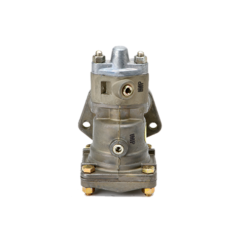
Safety Vlv A/M⚠WARNING: Cancer and Reproductive Harm - https://www.p65warnings.ca.gov/**Product Image May Not Be An Actual Representation of the Speci...

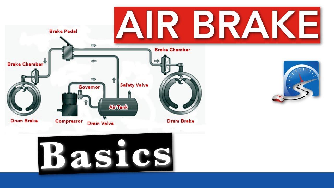
When we get in our semis and straight trucks to haul grain, we are glad when we hit the brake peddle to stop and we stop. The air brake system on our trucks is actually pretty simple and works the same on almost all trucks.
All air brake systems use air pressure to apply the brakes when you step on the pedal. The air is stored in a series of pressure tanks on the truck. The air is pressurized by the air compressor on the
The first system is the emergency system. This is the system that releases the parking brake and holds some reserve air to stop you if there is a leak. The way the parking brake system works on most trucks is there are springs in the air chambers on the rear axle or axles of the truck that apply the parking brakes. When you
push the parking brake knob in, this supplies air to those air chambers and pushes against the springs to release the parking brakes. If the pressure in the air system pulls below 60 psi the parking brake knob will pop out and set the parking brakes.
This is a safety feature so the truck will stop, because if the pressure falls too low, the service brakes will not work. If you are driving a semi tractor with a trailer, the trailer knob for the brakes works in the same way. But if there is an air leak in the trailer, the tractor protection valve will make the trailer brakes set to protect the tractor’s air supply so you can still stop.
The other system is the service brake system. This is the system that stops you when you push on the brake pedal. When you push on the brake pedal it goes through the pedal valve, which modulates the air flow to the brake chambers. The brake chambers in turn push on the slack adjusters, which is the component that keeps the brakes in adjustment. There are different types of slack adjusters — manual and automatic.
Manual slack adjusters are just as they sound. You must manually adjust them to keep the brakes in adjustment. These are, in my opinion, the best style to have.
The automatic slack adjusters automatically adjust themselves to keep the brakes in adjustment. These work well if you keep them greased. The problem is that most people don’t keep them greased and they seize up and don’t work. If you do have automatics, the best grease to use on them is white lithium grease.
There are such things as air disc brakes but they are not very common. Most brake shoes have an indicator built into the end of the pads that tell when they need to be replaced. When you replace the brake shoes you should also get hardware kits that include the springs, pins and bushings for the brakes. You should also always replace the drums when you replace the brake shoes. This is a good idea because the drums will have a wear ridge on them and could also have heat cracks in them.
The VBAT-Q tanks are CE certified for use in Europe and other countries that require compliance wtih the European Pressure Equipment Directive (PED). These units include a CE marked pressure relief valve and a drain valve.

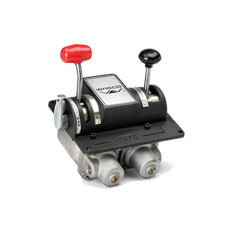
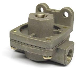
A relay valve is an air-operated valve typically used in air brake systems to remotely control the brakes at the rear of a heavy truck or semi-trailer in a tractor-trailer combination. Relay valves are necessary in heavy trucks in order to speed-up rear-brake application and release, since air takes longer to travel to the rear of the vehicle than the front of the vehicle, where the front service brakes, foot-valve, parking-control valve, and trailer-supply valve (if applicable) are located.
Without relay valves, it would take too long for sufficient air to travel from the brake pedal valve to the rear of the truck or trailer in order to apply the rear service brakes concurrently with the front service brakes, resulting in a condition known as brake lag. To correct this condition on a long-wheel-base vehicle, a relay valve is installed near the rear service brake chambers. In tractors as well as straight-trucks, a remote air-supply is provided in the form of a large diameter pipe connected between the primary reservoir and the relay valve for remote service brake application.
In a truck’s air brake system, relay valves get a signal when a driver presses the treadle, which then opens the valve and allows air to enter the brake chamber via air inlet. The diaphragm gets pushed, then the rod, then the slack adjuster which twists to turn the brake camshaft. Next, it moves the disc, wedge or s-cam, which pushes the brake shoes and lining, creating friction. This friction slows and eventually stops the brake drum’s turning, which stops the wheel.
In trailers, this remote air-supply is in the form of a tank, which is charged whenever the emergency brakes are released via the red trailer-supply valve on the dashboard. In a dual-circuit air brake system, this tank actually receives its air from both the primary and secondary reservoirs of the tractor; the air from both of these reservoirs is merged via a two-way check valve. The two-way check valve is a pneumatic device that has two inputs and one output; each input is connected to one these reservoirs. Only the air that is at the higher pressure is allowed to pass through to the check valve"s output, which then passes through the tractor-protection valve, and then travels onward towards the trailer"s air-tank and spring brake valve via the red trailer-supply line (a.k.a., the emergency line); this releases the trailer"s emergency brakes (a.k.a. spring brakes). The tractor-protection valve is a device that prevents air from being lost from the tractor"s braking system in the event of the air-lines becoming separated or broken. The tractor"s air-lines connect to the trailer"s air-lines via metal connectors known as gladhands. The merged air from both reservoirs of the tractor prevents air-loss from only one tractor braking circuit from causing the trailer"s spring brakes to automatically apply. This gives the driver more control, and prevents the vehicle from grinding to a halt in an unsafe location, such as in the middle of an intersection.
With a service brake relay valve installed, the hose that connects to the primary delivery-port output of the foot-valve becomes a control-line (i.e., The air from the foot-valve “dead ends” at the relay valve"s control-port.). Only low-volume air-signals are required to travel back and forth between the foot-valve"s delivery port and the relay valve"s control port; therefore, the air-volume supplied by the delivery port is now only a tiny-fraction of what otherwise would have been required had the relay valve not been installed. This reduces the delay between the application of the front and rear brakes to only a fraction of a second. When the driver depresses the brake pedal, a small amount of air momentarily opens the relay valve"s supply port, which then directs air from the remote air-supply directly to the rear service brake chambers, and quickly applies the rear service brakes. The pressure delivered to the service brake chambers in this manner will equal the control-pressure delivered by the foot-valve to the relay valve. When the driver partially or fully releases the brake pedal, the control-pressure delivered by the foot-valve decreases; this causes the relay valve"s supply port to close, and its exhaust port to momentarily open, thus preventing a pneumatic short-circuit from occurring while the air exhausts from all rear service brake chambers.
In order to control the trailer service brakes, the merged outputs (i.e., merged via 2 two-way check valves connected in-series to give three inputs) of the foot-valve and trailer-hand-valve (if applicable) are directed through the tractor-protection valve, and onward towards the trailer relay valve via the blue service line. In tractors that are not equipped with a trailer hand valve, only the merged outputs of the foot-valve (i.e., via a single two-way check valve) are directed towards the trailer relay valve; however, the fact that the foot-valve"s delivery-port outputs are still merged enables the trailer"s service brakes to still be controlled even if there is failure within one braking circuit of the tractor.
A spring brake relay valve works on the same principle as the service brake relay valve, although it has the opposite effect. This type of relay valve responds to a major drop in pressure at its control-port by opening its exhaust port, which causes the air from each spring brake chamber under its control to remotely exhaust, thus applying the spring brakes much-more-quickly than would otherwise be possible if the air were required to discharge via the yellow parking-control valve on the dashboard. In a dual-circuit air brake system, air from both the primary and secondary reservoirs is fed into the supply-port of the parking-control valve, as well as the supply-port of this relay valve; it is merged via yet another two-way check valve. The delivery-port output of the parking-control valve connects to the control-port of this relay valve; this enables the spring brakes to be controlled via this valve. The merged air from the parking-control valve prevents air-loss from only one braking circuit from causing the spring brakes to automatically apply. This gives the driver more control, and prevents the vehicle from grinding to a halt in an unsafe location. However, with this increased control, comes increased responsibility on the part of the driver: If air is lost from the primary circuit alone, the spring brakes must be manually applied by the driver via the parking-control valve; otherwise, the front service brakes may not be enough to stop the vehicle safely in an emergency—especially if the vehicle is heavily loaded, and/or traveling at a high-speed. In fact, the driver"s failure to manually apply the spring brakes in this situation could lead to catastrophic failure of the front brakes due to overheating, since it could cause the front service brakes to exceed their design-limit for energy absorption.
Relay valves are tested for durability before use through a seat test with air. In pressure at 80 psig or more, a 2-inch or smaller relay valve should not be tested for less than 15 seconds under pressure or for less than 30 seconds if it is at 3 inches in size.
상기와 같은 목적을 달성하기 위한 본 발명의 차량용 공기브레이크의 안티 컴파운드 시스템은, 주브레이크와 주차브레이크 이중 작동을 방지하기 위한 안티 컴파운드(anti-compound) 시스템에 있어서, 풋 컨트롤 밸브와 연결되는 리어 브레이크 릴레이 밸브와; 상기 리어 브레이크 릴레이 밸브의 일측에 설치되며, 상기 주차브레이크의 컨트롤 밸브와 연결되는 더블 체크 밸브를 포함하고, 이때, 상기 리어 브레이크 릴레이 밸브와 상기 더블 체크 밸브는 각각 리어 에어 챔버와 연결되며 구비되고, 상기 리어 에어 챔버는, 상기 리어 브레이크 릴레이 밸브와 연결된 제4포트와, 상기 더블 체크 밸브와 연결된 제5포트가 형성되며 압축공기가 채워진 실린더와; 상기 제4포트가 형성된 쪽으로 상기 실린더 내에 설치되어 작동되는 주브레이크 리턴 스프링과; 상기 제5포트가 형성된 쪽으로 상기 실린더 내에 설치되어 작동되는 주차 브레이크 압축 스프링과; 상기 주브레이크 리턴 스프링과 상기 주차 브레이크 압축 스프링을 작동되게 상기 실린더 내에 설치된 푸시로드;를 포함하여 된 것을 그 특징으로 한다.The anti-compound system of the vehicle air brake of the present invention for achieving the above object, in the anti-compound system for preventing the dual operation of the main brake and parking brake, the rear brake is connected to the foot control valve A relay valve; A double check valve installed at one side of the rear brake relay valve and connected to a control valve of the parking brake, wherein the rear brake relay valve and the double check valve are connected to a rear air chamber, respectively, The rear air chamber may include a cylinder having a fourth port connected to the rear brake relay valve and a fifth port connected to the double check valve and having compressed air filled therein; A main brake return spring installed and operated in the cylinder toward the fourth port; A parking brake compression spring installed and operated in the cylinder toward the fifth port; And a push rod installed in the cylinder to operate the main brake return spring and the parking brake compression spring.
도 2에는 본 발명에 따른 차량용 공기브레이크의 안티 컴파운드 시스템의 구성을 개략적으로 나타낸 구성 회로도가 도시되어 있다.2 is a configuration circuit diagram schematically showing the configuration of the anti-compound system of the vehicle air brake according to the present invention.
도면을 참조하면, 본 발명에 따른 차량용 공기브레이크의 안티 컴파운드 시스템은, 주브레이크와 주차브레이크 이중 작동을 방지하기 위한 것으로, 풋 컨트롤 밸브(22)와 연결되는 리어 브레이크 릴레이 밸브(40)와, 이 리어 브레이크 릴레이 밸브(40)의 일측에 설치되며, 상기 주차브레이크의 컨트롤 밸브와 연결되는 더블 체크 밸브(50)를 포함하여 구성된다.Referring to the drawings, the anti-compound system of the vehicle air brake according to the present invention is to prevent the dual operation of the main brake and the parking brake, the rear brake relay valve 40 is connected to the foot control valve 22, and It is installed on one side of the rear brake relay valve 40, and comprises a double check valve 50 is connected to the control valve of the parking brake.
이때, 상기 리어 브레이크 릴레이 밸브(40)와 더블 체크 밸브(50)는 각각 리어 에어 챔버(60)와 연결되며 구비된다.In this case, the rear brake relay valve 40 and the double check valve 50 are connected to the rear air chamber 60 and provided.
그리고 상기 더블 체크 밸브(50)는 후술하는 도 6 및 도 8에 도시된 바와 같 이, 리어 브레이크 릴레이 밸브(40)와 일체되게 구비된다.And the double check valve 50 is provided with a rear brake relay valve 40, as shown in Figures 6 and 8 to be described later.
또한 상기 더블 체크 밸브(50)는, 도 3에 도시된 바와 같이, 하우징(51)과, 이 하우징(51) 내에 형성된 유로(52)와, 이 유로(52)가 여러 방향으로 분기되게 다수개로 형성된 포트와, 이 포트를 단속하기 위해 유로(52)에 이동 가능하게 설치된 피스톤(53)을 포함하여 구성된다.In addition, as shown in FIG. 3, the double check valve 50 includes a plurality of housings 51, a flow path 52 formed in the housing 51, and a plurality of flow paths 52 diverging in various directions. And a piston 53 formed to be movable in the flow path 52 for intermittent the port.
그리고 상기 유로(52)에는 유로(52)에 형성된 압력을 외부로 공급하기 위한 공기압력 배출홀(54)이 형성된다.In addition, an air pressure discharge hole 54 for supplying the pressure formed in the flow path 52 to the outside is formed in the flow path 52.
또한 상기 포트는, 주차브레이크의 컨트롤 밸브와 연결된 배관에 연결되는 제1포트(55)와, 풋 컨트롤 밸브(22)가 연결된 배관에 연결되는 제2포트(56)와, 상기 제1,2포트(55,56)가 인렛 포트(inlet port)를 형성할 때 아웃렛 포트(outlet port)를 형성하기 위해 하우징(51)의 중앙에 형성된 제3포트(57)를 포함하여 구성된다.The port may include a first port 55 connected to a pipe connected to the control valve of the parking brake, a second port 56 connected to a pipe connected to the foot control valve 22, and the first and second ports. The first and second ports 55 and 56 include a third port 57 formed in the center of the housing 51 to form an outlet port when the inlet port is formed.
그리고 상기 리어 에어 챔버(60)는, 도 4에 도시된 바와 같이, 상기 리어 브레이크 릴레이 밸브(40)와 연결된 제4포트(61)와, 상기 더블 체크 밸브(50)와 연결된 제5포트(62)가 형성되며 압축공기가 채워진 실린더(63)와, 상기 제4포트(61)가 형성된 쪽으로 실린더(63) 내에 설치되어 작동되는 주브레이크 리턴 스프링(64)과, 상기 제5포트(62)가 형성된 쪽으로 실린더(63) 내에 설치되어 작동되는 주차 브레이크 압축 스프링(65)과, 상기 주브레이크 리턴 스프링(64)과 주차 브레이크 압축 스프링(65)을 작동되게 실린더(63) 내에 설치된 푸시로드(push rod)(66)를 포함하여 구성된다.In addition, as shown in FIG. 4, the rear air chamber 60 includes a fourth port 61 connected to the rear brake relay valve 40 and a fifth port 62 connected to the double check valve 50. A cylinder 63 filled with compressed air, a main brake return spring 64 installed and operated in the cylinder 63 toward the fourth port 61, and the fifth port 62 A parking rod compression spring 65 installed and operated in the cylinder 63 toward the formed side, and a push rod installed in the cylinder 63 to operate the main brake return spring 64 and the parking brake compression spring 65. 66).
도 3에 도시된 바와 같이, 상기 피스톤(53)은 더블 체크 밸브(50)의 내부에 장착된 하우징(파이프)(51) 내측에서 좌우로 자유롭게 이동한다. 상기 제1포트(55) 또는 제2포트(56)에 공기압력이 가해지면 피스톤(53)은 공기압력이 피스톤(53) 한쪽단면에 가해져 피스톤(53)이 공기압력이 가해진 반대방향으로 밀려나서 제1포트(55) 또는 제2포트(56) 한쪽 입구를 차단한다.As shown in FIG. 3, the piston 53 moves freely from side to side inside the housing (pipe) 51 mounted inside the double check valve 50. When air pressure is applied to the first port 55 or the second port 56, the piston 53 is pushed to one side of the piston 53, and the piston 53 is pushed in the opposite direction to which the air pressure is applied. One inlet of the first port 55 or the second port 56 is blocked.
이와 동시에 공기압력은 더블 체크 밸브(50) 내부 하우징(51) 중앙의 공기압력 배출홀(54)을 통해 아웃렛 포트(제3포트(57))로 공급된다. 만약 인렛 포트(제1,2포트(55,56)) 모두에서 공기압력이 가해질 경우, 압력이 높은 쪽의 공기압이 아웃렛 포트로 공급된다.At the same time, the air pressure is supplied to the outlet port (third port 57) through the air pressure discharge hole 54 in the center of the inner housing 51 of the double check valve 50. If air pressure is applied to both the inlet ports (first and second ports 55 and 56), the air pressure at the higher pressure side is supplied to the outlet port.
상기한 바와 같은 구성을 갖는 본 발명에 따른 차량용 공기브레이크의 안티 컴파운드 시스템의 작용을 설명하면 다음과 같다.Referring to the operation of the anti compound system of the vehicle air brake according to the present invention having the configuration as described above are as follows.
도면을 다시 참조하면, 본 발명에 따른 차량용 공기브레이크의 안티 컴파운드 시스템은, 저가형 안티 컴파운드 시스템이다.Referring back to the drawings, the anti-compound system of a vehicle air brake according to the present invention is a low-cost anti-compound system.
우선, 차량이 주행하는 조건에서는 상기 풋 컨트롤 밸브(22) 해제 상태이므로 풋 컨트롤 밸브(22) 이후의 배관에 있는 공기압력은 대기압 상태가 되므로 프론트 및 리어 에어 챔버(60",60) 내의 공기압력도 대기압 상태가 되어 휠브레이크는 해제상태를 유지한다.First, since the foot control valve 22 is released under the condition that the vehicle is running, the air pressure in the pipe after the foot control valve 22 is at atmospheric pressure, so the air pressure in the front and rear air chambers 60 "and 60 is reduced. At atmospheric pressure, the wheel brakes remain released.
그리고 파킹 노브(27)를 이용하여 주차브레이크 컨트롤 밸브를 주차브레이크 해제 위치로 놓으면 프론트와 리어 에어탱크의 공기압력이 4-CV(29)를 경유하여 배관 (14)까지 대기하고 있다가 배관(15)과 더블 체크 밸브(50)를 경유하여 배관(16)을 통해 리어 브레이크 챔버의 후방에 설치된 파킹 브레이크 챔버에 공압이 공급되면, 리어 에어 챔버(60)의 스프링(65)이 압축되므로서 휠브레이크를 작동하고있던 푸시로드(66)가 후퇴하여 주차브레이크는 도 4와 같은 해제 상태를 유지하게 된다.When the parking brake control valve is set to the parking brake release position by using the parking knob 27, the air pressure of the front and rear air tanks waits for the pipe 14 via the 4-CV 29, and then the pipe 15 When the pneumatic pressure is supplied to the parking brake chamber installed at the rear of the rear brake chamber via the pipe 16 via the double check valve 50), the spring 65 of the rear air chamber 60 is compressed and the wheel brake is applied. The push rod 66, which was operating, retracts and the parking brake is maintained in a released state as shown in FIG.
우선, 주차브레이크 작동 상태에서는, 주차브레이크 컨트롤 밸브(파킹 노브(27))를 주차브레이크 작동위치로 조작하면, 프론트와 리어 에어탱크의 공기압력이 4-CV(29)를 경유하여 배관(14)까지 대기하고 있던 공기압력이 배관(15)과 더블 체크 밸브(50)를 경유하여 파킹 브레이크 챔버에 공급되었던 공기압력이 배관(15)에서 리어 에어 챔버(60)까지의 구성품 내의 공기압은 파킹 노브(27)의 배출구를 통해 대기 중에 모두 배출되어 대기압력 상태가 된다.First, in the parking brake operating state, when the parking brake control valve (parking knob 27) is operated to the parking brake operating position, the air pressure of the front and rear air tanks is connected to the pipe 14 via the 4-CV 29. The air pressure that has been waiting until the air pressure supplied to the parking brake chamber via the pipe 15 and the double check valve 50 passes through the parking knob (from the pipe 15 to the rear air chamber 60). Through the outlet of 27), all air is discharged to atmospheric pressure.
따라서 도 5에 도시된 바와 같이, 리어 에어 챔버(60) 내에서 공기압력에 의해 압축되어 있던 스프링(65)이 인장되면서 푸시로드(66)를 전진시켜 휠브레이크를 작동시킨다. 이와 같은 상태를 주차브레이크 작동 상태라 한다.Accordingly, as shown in FIG. 5, the spring 65, which has been compressed by the air pressure in the rear air chamber 60, is tensioned and the push rod 66 is advanced to operate the wheel brake. This state is called parking brake operation state.
상기한 주차브레이크 작동 상태에서 주브레이크를 작동시키면 배관(11)을 통해 풋 컨트롤 밸브(22)까지 대기하고 있던 공기압력이 배관(12)을 경유하여 리어 브레이크 릴레이 밸브(40)를 지나 배관(13)에 공급된다.When the main brake is operated in the above-described parking brake operating state, the air pressure waiting for the foot control valve 22 through the pipe 11 passes through the rear brake relay valve 40 via the pipe 12 and passes through the pipe 13 Is supplied.
또한 도 6과 같이 더블 체크 밸브(50)를 경유하여 배관(16)에도 공급되어 도 7과 같이 공급된다. 각각 공급된 공기압력의 힘에 의해 리어 에어 챔버(60) 내에 인장된 스프링(65)이 압축되므로서 주차브레이크는 해제되고 주브레이크만 작동상태를 유지한다.In addition, it is supplied to the pipe 16 via the double check valve 50 as shown in FIG. 6 and is supplied as shown in FIG. The parking brake is released and only the main brake remains in operation as the springs 65 tensioned in the rear air chamber 60 are compressed by the force of the air pressure supplied, respectively.
그리고 상기한 주차브레이크 작동 상태에서 주브레이크를 해제하면 배관(13,16)을 통해 리어 에어 챔버(60)에 공급된 공기압이 도 8에 도시된 바와 같이 리어 브레이크 릴레이 밸브(40)의 배출구를 통해 빠져나가 리어 에어 챔버(60)의 공기압은 도 5와 같이 대기압 상태가 되어 주브레이크는 해제 상태를, 주차브레이크는 작동 상태를 유지한다.When the main brake is released in the parking brake operating state, the air pressure supplied to the rear air chamber 60 through the pipes 13 and 16 is discharged through the outlet of the rear brake relay valve 40 as shown in FIG. 8. After exiting, the air pressure of the rear air chamber 60 is at atmospheric pressure, as shown in FIG.
이어서, 주차브레이크 해제시 더블 체크 밸브(50)의 작동 상태를 설명한다.Next, the operation state of the double check valve 50 when the parking brake is released will be described.
주차브레이크를 해제시키기 위해 파킹 노브(27)를 파킹 해제 위치로 조작하면, 배관(14)에 대기하고 있던 공기압력이 배관(15)과 더블 체크 밸브(50)를 경유하여 배관(16)에 공급되므로서 리어 에어 챔버(60) 내에 인장된 스프링(65)이 압축되므로서 주차브레이크 해제 상태를 유지한다.When the parking knob 27 is operated to the unlocking position to release the parking brake, the air pressure waiting for the pipe 14 is supplied to the pipe 16 via the pipe 15 and the double check valve 50. As a result, the tensioned spring 65 in the rear air chamber 60 is compressed to maintain the parking brake released state.
이 과정에서 상기 더블 체크 밸브(50) 내의 피스톤(53)은 배관(15)의 공기압력에 의해 도 9와 같이 배관(12) 쪽으로 이동하여 배관(12)측의 관로는 차단시키고, 배관(15)측의 관로는 개방되므로, 배관(15)의 공기압이 배관(16)으로 공급된다.In this process, the piston 53 in the double check valve 50 moves toward the pipe 12 as shown in FIG. 9 by the air pressure of the pipe 15 to block the pipe line on the pipe 12 side, and the pipe 15 Since the pipe line on the) side is opened, the air pressure of the pipe 15 is supplied to the pipe 16.
그리고 주브레이크 작동 및 주차브레이크 해제가 동시에 조작된 경우, 더블 체크 밸브(50)의 작동 상태는, 도 9 또는 도 10과 같이 배관(12)과 배관(15) 중에 서 압력이 보다 높은 쪽의 공기압력이 배관(16)으로 공급된다.When the main brake operation and the parking brake release are operated at the same time, the operation state of the double check valve 50 is the air of the higher pressure in the pipe 12 and the pipe 15 as shown in Figs. Pressure is supplied to the pipe 16.
If you want to drive a truck or bus with air brakes or pull a trailer with air brakes, you need to study this section. If you want to pull a trailer with air brakes you also need to study Section 6: Combination Vehicles.
Air brakes use compressed air to make the brakes work. Air brakes are a good and safe way of stopping large and heavy vehicles when the brakes are well maintained and used properly.
The air compressor pumps air into the air storage tanks (reservoirs). The air compressor is connected to the engine through gears or a V-belt. The compressor may be air cooled or may be cooled by the engine cooling system. It may have its own oil supply or be lubricated by engine oil. If the compressor has its own oil supply, check the oil level before driving.
The governor controls when the air compressor will pump air into the air storage tanks. When air tank pressure rises to the “cut-out” level (around 125 pounds per square inch, or “psi”), the governor stops the compressor from pumping air. When the tank pressure falls to the “cut-in” pressure (around 100 psi), the governor allows the compressor to start pumping again.
Air storage tanks are used to hold compressed air. The number and size of air tanks vary among vehicles. The tanks will hold enough air to allow the brakes to be used several times even if the compressor stops working.
Compressed air usually has some water and compressor oil in it, which is bad for the air brake system. For example, the water can freeze in cold weather and cause brake failure. The water and oil tend to collect in the bottom of the air tank. Be sure to drain the air tanks completely. Each air tank is equipped with a drain valve in the bottom. There are two types of drain valves:
Some air brake systems have an alcohol evaporator to put alcohol into the air system. This helps reduce the risk of ice in air brake valves and other parts during cold weather. Ice inside the system can make the brakes stop working.
Check the alcohol container and fill up as necessary every day during cold weather. Daily air tank drainage is still needed to get rid of water and oil (unless the system has automatic drain valves).
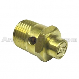
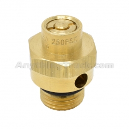
A safety relief valve is installed in the first tank the air compressor pumps air to. The safety valve protects the tank and the rest of the system from too much pressure. The valve is usually set to open at 150 psi. If the safety valve releases air, something is wrong. Have the fault repaired by a mechanic.
Make sure you study and memorize all of the below definitions. You must know how to distinguish between the three different types of brakes for the written exam. You will see these terms many times so it"s very important to memorize them now.
You"ll need to study and know each part listed in section 5.1 for the air brake system. Use flash cards if you need to, but all of these parts must be memorized.
For the written exam, you"ll need to understand the difference between "cut out level" and "cut in pressure". You"ll also need to know the air pressure level for each. Cut out pressure is around 125psi and cut in pressure is around 100psi. Be sure you have this memorized as it will come up quite often during your training.
Paccar Inc., one of several manufacturers whose trucks are affected by problems with a Bendix air-brake valve, has issued a recall that includes 21 Kenworth and Peterbilt models.
Some 50,000 to 60,000 trucks are affected, says Bendix Commercial Vehicle Systems, maker of the ATR-6 relay valve. Navistar International and Volvo said they are delaying shipment of thousands of trucks assembled with the valve and are notifying customers. Volvo"s sister company, Mack, said only 11 of its trucks are involved and customers have been notified.
A "potential intermittent air leak" in extreme cold can cause service brakes to apply and other operational problems, Bendix announced last week. Offending valves were made between December 2, 2011, and January 18, 2012. Truck builders are now using a different valve for current production.
Owners of recently built International, Kenworth, Peterbilt and Volvo trucks should inspect the vehicles" relay valves to see if they are among the defective units, Bendix says. If so, the trucks should be taken to dealers for servicing. Inspection instructions and other information are on Bendix"s website.
Its recall notes the possibility of "unexpected continuous brake application," and says that this "can cause the brakes to overheat and lead to a fire" and "can cause the driver to lose control of the vehicle, increasing the risk of a crash.
Bendix said that a "temporary remedy kit" will allow affected trucks to stay in service. The kit contains an O-ring and a plug that, when inserted into the valve, disables its stability control function. A permanent fix is forthcoming, the company said.
Navistar International"s chairman, Daniel Ustian, told stock analysts last week that delaying shipments of trucks is expected to contribute to first-quarter financial losses. The other manufacturers have not made similar statements.
In this article, we’ll explore how the brake booster check valve works and how to spot issues with it. We’ll also highlight a simple repair solution if you’re experiencing problems.
The vacuum brake booster operates on a simple pressure differential theory. It comes with several parts that all serve different functions — like the diaphragm, pushrod, dust boots, check valve and grommet, and so on.
When the driver presses down on the brake pedal, air enters one chamber, creating atmospheric pressure that pushes against the diaphragm. This pressure amplifies the forces from the brake pedal to the master cylinder, stopping your car quickly.
However, that also means that it’s usually harder to notice a potentially failing check valve (unlike thinning brake pads or even a brake fluid leak).
Reduced vacuum in the booster means less amplifying power. This means you’d need to press down harder on the brake pedal to get the vehicle’s brakes to engage.
Changes in how your brake pedal feels are usually due to potential issues in the power brakes, and you need to get your vehicle to a mechanic as soon as you can.
If the booster check valve is blocked, it won’t suck out air molecules from the vacuum brake booster as efficiently. And if it’s broken, it may let airinto the brake booster.
As the bad check valve gradually loses effectiveness, the air that it should regulate can end up in the brake master cylinder, enter the brake fluid, and progress as air bubbles in the brake line.
Anyair bubble in the brake fluid is going to reduce the hydraulic pressure that flows back and forth between the master cylinder and brake caliper at each wheel.
They’ll remove the vacuum hose and the check valve that runs from the brake booster to the intake manifold of the engine. They’ll likely use a screwdriver or pliers to remove the hose clip or hose clamp.
An aspirator bulb can be used to blow air into the hose. If air enters the hose, the booster check valve is leaking air and needs to be replaced. If this is due to a broken grommet, then the fix is as simple as replacing that grommet.
Sometimes the check valve is built into the vacuum hose and can’t be serviced separately. In this case, your mechanic will likely have to replace both the hose and check valve.
The average brake booster check valve replacement will cost around $100-$130. However, you should be aware that repairs might involve more than a check valve fix.
If your brake booster check valve has been faulty for a while, other brake system parts could have been affected — like possible air bubbles in the brake lines that need to be bled out.
- Select -AfghanistanAlbaniaAlgeriaAmerican SamoaAndorraAngolaAnguillaAntarcticaAntigua & BarbudaArgentinaArmeniaArubaAscension IslandAustraliaAustriaAzerbaijanBahamasBahrainBangladeshBarbadosBelarusBelgiumBelizeBeninBermudaBhutanBoliviaBosnia & HerzegovinaBotswanaBouvet IslandBrazilBritish Indian Ocean TerritoryBritish Virgin IslandsBruneiBulgariaBurkina FasoBurundiCambodiaCameroonCanadaCanary IslandsCape VerdeCaribbean NetherlandsCayman IslandsCentral African RepublicCeuta & MelillaChadChileChinaChristmas IslandClipperton IslandCocos (Keeling) IslandsColombiaComorosCongo - BrazzavilleCongo - KinshasaCook IslandsCosta RicaCroatiaCubaCuraçaoCyprusCzechiaCôte d’IvoireDenmarkDiego GarciaDjiboutiDominicaDominican RepublicEcuadorEgyptEl SalvadorEquatorial GuineaEritreaEstoniaEswatiniEthiopiaFalkland IslandsFaroe IslandsFijiFinlandFranceFrench GuianaFrench PolynesiaFrench Southern TerritoriesGabonGambiaGeorgiaGermanyGhanaGibraltarGreeceGreenlandGrenadaGuadeloupeGuamGuatemalaGuernseyGuineaGuinea-BissauGuyanaHaitiHeard & McDonald IslandsHondurasHong Kong SAR ChinaHungaryIcelandIndiaIndonesiaIranIraqIrelandIsle of ManIsraelItalyJamaicaJapanJerseyJordanKazakhstanKenyaKiribatiKosovoKuwaitKyrgyzstanLaosLatviaLebanonLesothoLiberiaLibyaLiechtensteinLithuaniaLuxembourgMacao SAR ChinaMadagascarMalawiMalaysiaMaldivesMaliMaltaMarshall IslandsMartiniqueMauritaniaMauritiusMayotteMexicoMicronesiaMoldovaMonacoMongoliaMontenegroMontserratMoroccoMozambiqueMyanmar (Burma)NamibiaNauruNepalNetherlandsNetherlands AntillesNew CaledoniaNew ZealandNicaraguaNigerNigeriaNiueNorfolk IslandNorthern Mariana IslandsNorth KoreaNorth MacedoniaNorwayOmanOutlying OceaniaPakistanPalauPalestinian TerritoriesPanamaPapua New GuineaParaguayPeruPhilippinesPitcairn IslandsPolandPortugalPuerto RicoQatarRomaniaRussiaRwandaRéunionSamoaSan MarinoSaudi ArabiaSenegalSerbiaSeychellesSierra LeoneSingaporeSint MaartenSlovakiaSloveniaSolomon IslandsSomaliaSouth AfricaSouth Georgia & South Sandwich IslandsSouth KoreaSouth SudanSpainSri LankaSt. BarthélemySt. HelenaSt. Kitts & NevisSt. LuciaSt. MartinSt. Pierre & MiquelonSt. Vincent & GrenadinesSudanSurinameSvalbard & Jan MayenSwedenSwitzerlandSyriaSão Tomé & PríncipeTaiwanTajikistanTanzaniaThailandTimor-LesteTogoTokelauTongaTrinidad & TobagoTristan da CunhaTunisiaTurkeyTurkmenistanTurks & Caicos IslandsTuvaluU.S. Outlying IslandsU.S. Virgin IslandsUgandaUkraineUnited Arab EmiratesUnited KingdomUnited StatesUruguayUzbekistanVanuatuVatican CityVenezuelaVietnamWallis & FutunaWestern SaharaYemenZambiaZimbabweÅland Islands


 8613371530291