
air compressor safety valve keeps opening made in china
If the tank is over pressurized, the pressure switch isn"t shutting off the motor when the air tank fills to the cut-out pressure. Move the pressure switch lever to the off position. If the compressor continues to run, replace the pressure switch, because the switch isn"t shutting off the compressor motor.
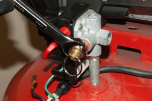
If the compressor shuts off when you move the pressure switch lever to the off position, pull the safety valve ring and release all air from the tank. Switch the pressure switch lever to the on position and allow the tank to fill. If the compressor doesn"t shut off when the air tank fills to the cut-out pressure, replace the pressure switch, because the switch isn"t shutting off the compressor motor when tank pressure reaches the cut-out pressure.
What happens when you pressurize an air tank beyond its rated pressure? It fails catastrophically and ruptures in a spectacular way that you wouldn’t want to witness firsthand.
Most air compressors have a number of precautions built in to avoid the risk of a tank rupture. The compressor itself will probably have an automatic shut-off control that turns off the motor once the maximum tank pressure is reached.
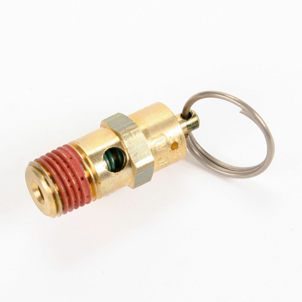
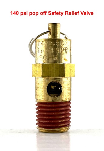
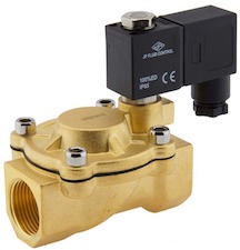
In case the auto-shutoff switch fails, there will typically also be a safety valve built into the tank. Such safety valves, such as the Conrader hard seat valve shown above, are rated to specific pressures. A 100 PSI valve will open up at ~100 PSI in order to vent excess air to keep the pressure at or below 100 PSI.
Essentially, safety valves have spring-loaded pistons. Below their factory-set pressures, internal springs hold the pistons downward, creating a seal. But once the pressure inside a tank or device overcomes the built-in pressure limit of a safety valve, the piston is pushed upwards, opening the valve seal to lower and equalized the air pressure.
Safety valves typically also have loops attached to the pistons so that you can manually rapidly depressurize a device or air tank. You should check safety valves every now and then to ensure they can open freely.
There are two main types of safety valves – hard seat and soft seat valves. Hard seat valves are rugged and inexpensive, but typically leak a little bit. Soft seat valves are a little less rugged and more expensive, but they are built with better seals that aren’t as prone to leaking.
I went with Conrader hard seat valve for a recent project, but there are other good brands as well. Safety valves are available in a wide range of pressures and in different styles.
Amazon carries a couple of valves directly and through 3rd party vendors, but your best bet is to check with Grainger, Zoro, McMaster Carr, or another industrial suppliers that have wider selections.
Conventionally when we talk about oil lubricated screw air compressor maintenance, it is mostly about replacing consumables such as filters and lubricant on time. While these consumables have a defined usable life and have a direct effect on the efficiency and the life of the air compressor itself when not replaced on time, there are a few critical valves in the air compressor that require maintenance as well. Compressor valves directly affect the efficiency, safety, and the functionality of the screw air compressor. Let us understand some of the commonly available valves in a screw air compressor, why they need maintenance, and discuss some of the frequently asked questions about screw air compressor valves.
A screw air compressor is very similar to a human heart. While a human heart has tricuspid, pulmonary, mitral, and aortic valves, a screw air compressor has four critical valves namely air inlet, minimum pressure, blow down, and safety valves.
Air inlet valve is also commonly known as the ‘Intake valve’ which is typically assembled on the airend’s intake. The air inlet valve of a conventional fixed speed screw air compressor controls the air intake into the compressor. It remains closed when the compressor starts to lower the starting load on the main motor and when the desired working pressure is attained in the compressed air circuit and thus enabling the compressor’s motor to run without any load. In some compressors that are capable of providing a variable output by modulating the amount of air it sucks in, the inlet valve holds various opening positions to regulate the volume of air entering the compressor. The effective performance of the inlet valve directly affects the compressor’s capacity and its power consumption during load and no-load conditions.
The minimum pressure valve is typically assembled on the exit of the air-oil separation tank of a compressor. The minimum pressure valve acts as a check valve preventing back flow of compressed air into the airend, retains a minimum pressure in the compressor system for lubrication, offers a restriction to avoid a collapse of the air-oil separation filter, and ensures a suitable velocity of flow across the air-oil separator that ensures efficient air-oil separation. The effective performance of the minimum pressure valve directly affects the compressor’s lubrication, air-oil separation efficiency, and power consumption during load and no-load conditions.
The blow down valve is typically found on a dedicated exhaust line from the air-oil separation tank. The blow down valve evacuates the compressed air in the air-oil separation tank each time the compressor runs on a no-load and when the compressor shuts down to ensure there is no back pressure when the compressor starts to load next time. The blow down valve of a conventional screw compressor is typically actuated by a solenoid valve. The effective performance of the blow down valve affects the compressor’s power consumption during un-load, capacity of the compressor when running on load, and the life of the motor.
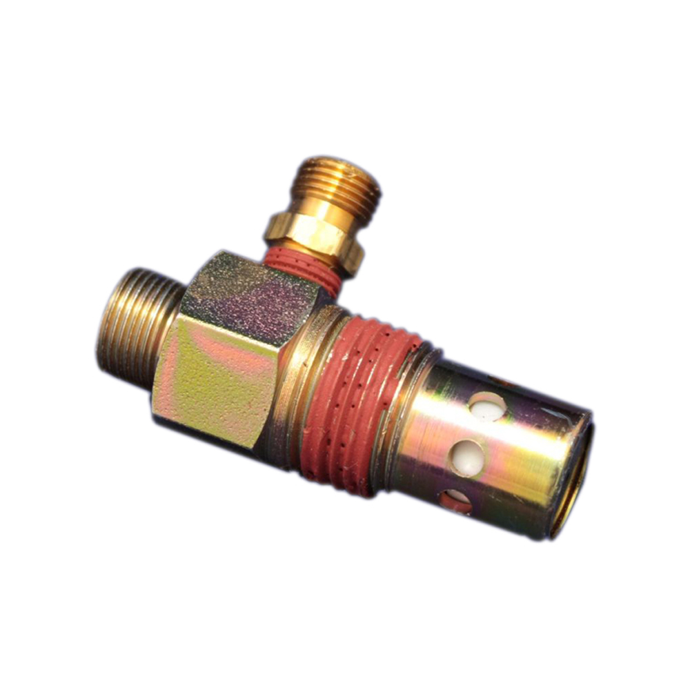
The safety valve is typically mounted directly on the air-oil separator tank. The only function of the safety valve is to blow off the compressed air in the air-oil separation tank when the pressure in the air-oil separation tank exceeds the set pressure of the safety valve and there by prevents the tank from cracking under high pressure. A malfunctioning safety valve affects the safe operation of the air compressor or results in leakage of compressed air continuously.
Though each compressor manufacturer has their own unique valve design, compressor valves in general contain moving parts such as springs, valve plates, and plungers that affect the opening and closing of the valves and rubber seals / seats that offer perfect sealing when the valves remain closed. These moving parts wear or lose their mechanical properties over a period of time and the sealing components typically ‘age’ over time and lose their effectiveness and will need to be replaced.
Compressor manufacturers typically design these components to operate efficiently for several thousand or millions of operation cycles. However, several factors such as variability in the demand pattern, sizing of the air compressor against a certain air demand, the environment in which the air compressor operates, promptness of preventive maintenance, etc. determine how long these valves efficiently operate.
Many times, it is difficult to identify a malfunctioning valve or a valve operating with worn-out parts as the compressor continues to generate air. The typical symptoms of a malfunctioning valve are loss in compressor"s capacity, increase in power consumption during load or/and unload, drop in discharge pressure, increase in oil carry-over and more load on motor. These symptoms are either difficult to notice or have other frequently common assignable causes such as air leak before suspecting the compressor valves.
Case studies show that operating a screw air compressor with a worn-out / malfunctioning valve could increase its overall power consumption by 10 - 15%. Power cost contributes to more than 75% of the compressor’s total life cycle cost over ten years and hence this is a significant impact. Unserviced valves also lower the life span of downstream accessories by half. In some cases, a malfunctioning safety valve may result in a catastrophe.
Air compressor manufacturers typically offer convenient valve maintenance kits for customers that contain the internal parts of the valve that wear or age out. Changing the valve kits is a much more sensible and economical option than changing the complete valve.
It is difficult or almost impossible to identify a malfunctioning valve unless it is opened for inspection. Hence it is absolutely mandatory that these valves are inspected for effectiveness every year and the internal moving parts replaced as a part of preventive maintenance once every year or two depending on the operating conditions of the air compressor. It is typical for compressor manufacturers to mandate a valve kit replacement once every two years as a proactive measure.
In particular, the safety valve must be inspected and certified every year per the local safety laws to ensure they are functional and efficient. Sometimes, replacing the safety valve entirely with a valid certificate for one year is more economical as the certification procedures could be equally expensive on an existing valve.
As stated before, it is challenging to identify a valve that is worn out unless it is opened and inspected, but there are a few indicators that a qualified compressor technician can use to deduct a malfunctioning valve.
Low duty cycle operation: A sophisticated screw air compressor in today’s day and age carries a convenient microprocessor-based human-machine interface that keeps track of operating hours of the compressor under load and un-load conditions and the number of load/unload counts the compressor is subjected to over a period of time. A higher un-load hours and load/unload count indicates that the air compressor is oversized against the actual air demand. This in turn indicates the air compressor ‘cycles’ frequently between load and un-load mode as opposed to running continuously on load. Every time a compressor ‘cycles’, the inlet valve, blow down valve, and minimum pressure valve is brought into play where their internals ‘actuate’. Frequent actuation of these valves results in a faster wear of the internals and hence results in shorter life.
High operating temperature: A compressor that runs on a high operating temperature affects the life of the valve’s sealing components, which causes them to ‘age’ fast.
Compressor not building pressure: If the air demand has not changed over time and the facility is relatively free of any air leakage, the air compressor is probably not delivering the rated output. There is a high probability that there is a malfunctioning valve.
Increase in compressor’s power consumption: An increase in the air compressor’s power consumption profile over a period of time where there has been no abnormal change in the air demand and usage pattern indicates an increase in either the load or un-load power. There is a high probability that this is because of a malfunctioning valve.
Based on the design philosophy adopted by the air compressor manufacturer, the oil lubricated screw air compressors could have a few more valves that are critical to functional performance that must be maintained as well. Some of the other valves frequently used in an air compressor are as follows:
Temperature control valve (also known as thermal valve) is used to regulate the flow of oil through the oil cooler based on the operating temperature.
Drain valves are used to drain lubricant at the time of lubricant change over or cleaning. Air compressors equipped with a moisture trap at the outlet of the after cooler also has a drain valve (automatic or timer based) to discharge water collected
The presence or absence of one of these valves and the type of actuation of these valves (electronic / mechanical) depends on air compressor’s design architecture. The Operation and Maintenance Manual (OMM) and the Piping and Instrumentation Diagram (P&ID) supplied by the air compressor manufacturer are excellent resources that explain the purpose, functioning, and maintenance requirements of these valves.
Many of the air compressor valves are highly specialized and exclusive. Their designs are usually complex and some even need special tools to service them. The internal components" build quality and material selection are extremely important and proprietary. Hence it is highly critical that only genuine valve kits issued by the air compressor manufacturer are used to maintain the valves. An inferior after-market replacement will most certainly compromise the performance of the entire compressor, void the original manufacturer"s warranty of the compressor, cause consequential damage to other parts of the compressor, and above all, be a safety hazard.
In conclusion, while it is important to change the screw air compressor"s filters and lubricants on time, it is equally important to perform preventive maintenance on these critical valves in a screw air compressor as recommended by the air compressor manufacturer. While the intake valve, minimum pressure valve, safety valve, and blowdown valve are critical to the performance and safety of the compressor, there could be other valves in the compressor that are critical and need maintenance. The air compressors sizing and the environment in which it operates are crucial factors that affect the life of the air compressor. Finally, it is critical to proactively service these valves using genuine kits issued by the compressor manufacturer to enable the air compressor performs efficiently and safely.

A reciprocating air compressor is a positive displacement mechanical device that relies on a cylinder and crankshaft-driven piston to produce compressed air. An unloader valve is one of the many small but essential parts and components that ensure the effective, efficient operation of a reciprocating compressor.
A compressor unloader valve is a small part, typically measuring approximately 4-5 inches in length and width. It performs the critical function of releasing trapped air inside the tank, enabling the motor to restart. An unloader valve malfunction is one of the more common air compressor issues. If the trapped air cannot escape, the accumulated pressure may be enough to keep the motor from restarting.
The type of unloader valve found in an air compressor depends on the machine’s make and size. Some operate via a toggle switch on the side of the unit’s pressure switch. Others have an integral valve installed under the pressure switch.
During the operation of a typical reciprocating air compressor, the machine’s electric motor-driven tank fills with air. The device contains a pressure switch that responds to the air accumulation by shutting off the motor’s power supply. The compressor pump, which is attached to the motor shaft, also stops.
When the motor attempts to restart, the air trapped inside the cylinder generates a load that makes it more challenging to execute the task. By venting the air, the unloader valve reduces the load over the piston, facilitating the restarting process.
If you own a smaller reciprocating air compressor, you’ll likely find the unloader valve mounted on or inside the pressure switch. When the switch shuts the compressor off, it actuates the valve. A small tube or pipe runs from the check valve, a device that keeps the entire tank from draining, to the unloader valve.
A larger air compressor often features a more sizeable unloader valve controlled by air pressure emanating from a smaller pilot valve. In this arrangement, the valve typically sits next to the compressor.
When the air pressure inside the compressor’s tank reaches the pressure switch’s cut out pressure (the point when air is no longer delivered), the switch automatically trips off and interrupts the power supply to the motor. This process causes the unloader valve to open and vent the accumulated air.
When the tank pressure drops back down to the predetermined setting on the pressure switch, it causes the switch to trip again. This action results in the release of the unloader valve’s pin, preventing the escape of compressed air into the atmosphere.
As a leading provider of high-quality compressed air equipment for companies in a wide range of industries, Quincy Compressor can answer all your questions about unloader valves, their purpose and how they work. Feel free to contact us today for more information.

The air compressor pressure switch measures the pressure inside your air tank and shuts off your compressor when it reaches the air pressure you need.
The air compressor pressure switch will also help your machinery maintain the proper pressure level as you go about your work. The switch can turn on your compressor when tank air pressure levels drop and more air is needed.
This makes your air compressor pressure switch a part that gets used often, and so it may wear down sooner than others. You’ll want to keep it properly maintained and fix it, or replace it when any problems arise. The switch is your best protection against an over-pressurized tank and air lines for your compressor, keeping you safe from ruptures and dangers.
Air compressor pressure switches use air lines to monitor pressurized air as it moves to and from your air tank. All pressure switches have an element that reacts when pressure is applied to it. The most common device is a diaphragm that will deform or compress when exposed to pressurized air.
Air pressure in your compressor tank will increase and eventually build up enough backward pressure — also called cut-out pressure — to change the shape of this diaphragm. Deformation here will cause movement in the pressure switch.
When your air compressor pressure switch’s diaphragm is deformed enough, its movement will break contact inside the switch so that power stops flowing to the compressor’s motor circuit, preventing the compressor from further pressurizing the air in your tank.
Constant air pressure at a specific volume will keep the diaphragm deformed. When the air pressure in your tank drops far enough, the membrane will revert back to its normal shape. Once this pressure — called cut-in pressure — lightens to a certain level, an internal operator within the diaphragm will deform in an opposite manner. This movement closes the circuit and starts the motor back up again.
Your air compressor pressure switch continues this dance as long as your machinery is using compressed air. The cycle is broken when the unit is no longer powered externally or when there is an issue. Leaks at any point in your compressor’s pressure switch and nearby casing can stop your work and cause major problems.
The switch is usually mounted on the reservoir so the air in the air tank can flow freely to the switch. Your pressure switch will monitor the air coming from this compressor tank, so you know how much pressure you’re using and can determine if there is an issue.
Compressed air will push equally in every direction and on all sides of the switch at the same time, so damage to the housing or the reservoir can cause a problem in getting correct readings.
Terminals: The pressure switch completes or breaks an electric circuit, thus telling the air compressor when to turn on. The incoming and outgoing wiring is connected through the terminals to the pressure switch.
Contacts: The contacts are two points in the pressure switch which separate and come together to complete or break the circuit. They are made of a conductive metal, and when the contacts are separated, and the circuit is interrupted, the motor of the air compressor will shut off.
Diaphragm: Also called a membrane, a diaphragm is a piece of flexible material that moves when the pressure inside the air tank changes. When the pressure increases, the air pushes against this membrane. When the desired pressure is reached, it pulls the conductive contact points apart, breaking the circuit.
Pressure switch relief valve: This safety valve is designed to relieve pressure trapped between the pump and the check valve. It can be found on the base of the pressure switch control, where it’s connected to the check valve with a nylon or copper tube. The valve is activated when the contacts separate.
Adjustment springs: You can adjust the cut-in and cut-out points for the air compressor with a spring. When you tighten the spring, more pressure needs to be applied from the diaphragm before the spring forces the contacts apart. When you loosen the spring, it will move with less pressure.
Auto/on/off lever: Some pressure valves have an auto/off or on/off knob or lever to control the pressure switch. When it is on the “auto” or “on” setting, it will work with the determined cut-in and cut-out settings to determine when the motor turns on and off. When it is off, a piece of plastic becomes wedged between the contacts, keeping the power to the engine off.
You can easily test your own air compressor pressure switch with an ohmmeter and a separate air source. Proper testing can save you a lot of time and headaches on air compressor switch repair:
Locate the valve and apply air to your pressure switch. Be sure to use a source that delivers more air pressure than the switch’s current setting. If you’re not using enough pressure, the switch won’t engage.
Compressor switches often end up leaking after a long life of use. Thankfully, you’ll find that the most common cause for switch leakage is something you can check and fix.
Over time, the diaphragm inside the air compressor pressure switch can crack or get a hole worn in it. When this occurs, air will blow around and leak from the tank, moving through the diaphragm and out of any opening in the switch housing.
When your switch’s unloader valve is located on the outside of the housing, this is the first place to look for leaks. Air leaking from this valve or near its connection to the cover will usually indicate a hole or other problem with the diaphragm.
These types of leaks can be difficult to resolve for many people. Sometimes problems occur with getting the proper diaphragm replacement. Customers have also noted concerns with parts or new issues after they’ve disassembled and reassembled their air compressor pressure switch.
Depending on cost, you might be able to save money and effort by replacing the pressure switch. Purchase a new switch, and you can expect a longer life from your air compressor because you’re getting a new diaphragm, points and other parts that tend to wear down over time.
Concerned you may be having an issue with the unloader valve and experiencing air compressor pressure switch leakage? Let’s look at the unloader valve itself and see what its leaks may look like.
The unloader valve is a needle valve that monitors your pressure switch and responds to the pressure switch’s movements. It activates and is opened when the compressor motor shuts off, creating that telltale hiss present in any properly working air compressor.
You can tell air is leaking from this valve when the hiss lasts for more than a few seconds or if you can feel a steady stream of compressed air at the bottom of the valve. Sometimes these unloader valves just need to be cleaned, though a major crack or distortion means they’ll need to be replaced.
Some air compressors will have a 100 percent duty cycle that means they can be used continuously and not overheat. These heavy-duty models are designed to prevent motor damage through constant use. Other compressor systems will have a limited duty cycle, so that prolonged use may cause harm to the unit.
Not adhering to a limited duty cycle can cause significant overheating and damage to your air compressor. The damage not only threatens the motor, but the heat can lead to an air compressor pressure switch leaking if friction is caused or the heat generated is localized near your pressure switch.
This type of issue often occurs when workers are using two compressors with a single compressor tank. That dynamic changes the workload on each compressor. If you’re running this setup and aren’t sure how to adjust operations or swap compressors, reach out to us today to make sure you’re not at risk of a major equipment failure.
Picking the right air compressor pressure switch starts with learning the pressure requirements of your air compressor. Perhaps most important is to find the manual and determine the cut-in pressure range. Your new switch should operate at the lowest cut-in pressure value in your range to prevent damage.
Aim a little higher for the cut-in pressure, setting your unit 5 psi to 10 psi higher than the requirement to keep everything running smoothly. This buffer will give your air compressor enough time to start working and catch up.
Electrical load:Make sure your new pressure switch can handle motor currents if you’re using a smaller compressor. If you’re unsure about the requirement, look to your manual or contact our staff for assistance.
Pressure maximums: Compressors are rated for a specific max pressure. Make sure your new switch is rated for that pressure or higher. Also, be careful to never set a pressure setting higher than your compressor or switch can handle.
These are just a few of the elements central to your air compressor pressure switch. Matching your new switch as closely as possible to the older switch is always your best bet unless an upgrade has been made available.
In most compressors, replacing the switch is straightforward. This is a general process, and your steps may vary, but it is standard for air compressor pressure switch repair:
Remove the quick-connect compression fitting, pressure regulator and top gauge from the pressure switch. You’ll either have to use a small pipe wrench or a set of slip-joint pliers to get these off. Start by loosening the nut attached to the unloader valve’s air line, and pull this up out of its fitting.
That is the basic set of steps to replacing your pressure switch and unloader valve. Advanced compressors may have larger systems that are more complex and require a broader set of tools and parts to successfully replace your air compressor pressure switch and other parts.
Sometimes a pressure switch leaks air when there is another problem in your system. One common cause comes from the unloader valve itself. If your unloader valve is leaking, you may want to reach out to a professional for a full inspection and repair.
To tell if your issue is from the unloader valve, we’ll check for a leak when the air compressor is off. This type of leak means you’re looking at a problem with the valve as well as the compressor tank’s check valve. Problems can include failures in the valve to close, improper sealing, or even damage and cracks to one of these parts.
In this case and with leaking due to wear over time, it can be difficult to get the parts you need for your air compressor pressure switch. Reach out to our professional staff for a quick check if you’re finding it tough to get parts or aren’t sure what parts you need.
Let’s say you tried to fix it yourself, and you’re still experiencing air compressor pressure switch leaking. Don’t just assume your new pressure switch is faulty. The tank check valve, unloader valve and other elements may be responsible for your woes.
Pressure relief valves (safety relief valves) are designed to open at a preset pressure and discharge fluid until pressure drops to acceptable levels. The development of the safety relief valve has an interesting history.
Denis Papin is credited by many sources as the originator of the first pressure relief valve (circa 1679) to prevent overpressure of his steam powered “digester”. His pressure relief design consisted of a weight suspended on a lever arm. When the force of the steam pressure acting on the valve exceeded the force of the weight acting through the lever arm the valve opened. Designs requiring a higher relief pressure setting required a longer lever arm and/or larger weights. This simple system worked however more space was needed and it coud be easily tampered with leading to a possible overpressure and explosion. Another disadvantage was premature opening of the valve if the device was subjected to bouncing movement.
Direct-acting deadweight pressure relief valves: Later to avoid the disadvantages of the lever arrangement, direct-acting deadweight pressure relief valves were installed on early steam locomotives. In this design, weights were applied directly to the top of the valve mechanism. To keep the size of the weights in a reasonable range, the valve size was often undersized resulting in a smaller vent opening than required. Often an explosion would occur as the steam pressure rose faster than the vent could release excess pressure. Bouncing movements also prematurely released pressure.
Direct acting spring valves: Timothy Hackworth is believed to be the first to use direct acting spring valves (circa 1828) on his locomotive engine called the Royal George. Timothy utilized an accordion arrangement of leaf springs, which would later be replaced with coil springs, to apply force to the valve. The spring force could be fine tuned by adjusting the nuts retaining the leaf springs.
Refinements to the direct acting spring relief valve design continued in subsequent years in response to the widespread use of steam boilers to provide heat and to power locomotives, river boats, and pumps. Steam boilers are less common today but the safety relief valve continues to be a critical component, in systems with pressure vessels, to protect against damage or catastrophic failure.
Each application has its own unique requirements but before we get into the selection process, let’s have a look at the operating principles of a typical direct acting pressure relief valve.
In operation, the pressure relief valve remains normally closed until pressures upstream reaches the desired set pressure. The valve will crack open when the set pressure is reached, and continue to open further, allowing more flow as over pressure increases. When upstream pressure falls a few psi below the set pressure, the valve will close again.
Most commonly, pressure relief valves employ a spring loaded “poppet” valve as a valve element. The poppet includes an elastomeric seal or, in some high pressure designs a thermoplastic seal, which is configured to make a seal on a valve seat. In operation, the spring and upstream pressure apply opposing forces on the valve. When the force of the upstream pressure exerts a greater force than the spring force, then the poppet moves away from the valve seat which allows fluid to pass through the outlet port. As the upstream pressure drops below the set point the valve then closes.
Piston style designs are often used when higher relief pressures are required, when ruggedness is a concern or when the relief pressure does not have to be held to a tight tolerance. Piston designs tend to be more sluggish, compared to diaphragm designs due to friction from the piston seal. In low pressure applications, or when high accuracy is required, the diaphragm style is preferred. Diaphragm relief valves employ a thin disc shaped element which is used to sense pressure changes. They are usually made of an elastomer, however, thin convoluted metal is used in special applications. Diaphragms essentially eliminate the friction inherent with piston style designs. Additionally, for a particular relief valve size, it is often possible to provide a greater sensing area with a diaphragm design than would be feasible with a piston style design.
The reference force element is usually a mechanical spring. This spring exerts a force on the sensing element and acts to close the valve. Many pressure relief valves are designed with an adjustment which allows the user to adjust the relief pressure set-point by changing the force exerted by the reference spring.
The chemical properties of the fluid should be considered before determining the best materials for your application. Each fluid will have its own unique characteristics so care must be taken to select the appropriate body and seal materials that will come in contact with the fluid. The parts of the pressure relief valve in contact with the fluid are known as the “wetted” components. If the fluid is flammable or hazardous in nature the pressure relief valve must be capable of discharging it safely.
In many high technology applications space is limited and weight is a factor. Some manufactures specialize in miniature components and should be consulted. Material selection, particularly the relief valve body components, will impact weight. Also carefully consider the port (thread) sizes, adjustment styles, and mounting options as these will influence size and weight.
In many high technology applications space is limited and weight is a factor. Some manufactures specialize in miniature components and should be consulted. Material selection, particularly the relief valve body components, will impact weight. Also carefully consider the port (thread) sizes, adjustment styles, and mounting options as these will influence size and weight.
A wide range of materials are available to handle various fluids and operating environments. Common pressure relief valve component materials include brass, plastic, and aluminum. Various grades of stainless steel (such as 303, 304, and 316) are available too. Springs used inside the relief valve are typically made of music wire (carbon steel) or stainless steel.
The materials selected for the pressure relief valve not only need to be compatible with the fluid but also must be able to function properly at the expected operating temperature. The primary concern is whether or not the elastomer chosen will function properly throughout the expected temperature range. Additionally, the operating temperature may affect flow capacity and/or the spring rate in extreme applications.
Beswick Engineering manufactures four styles of pressure relief valves to best suit your application. The RVD and RVD8 are diaphragm based pressure relief valves which are suited to lower relief pressures. The RV2 and BPR valves are piston based designs.

If leaking seals and service bills are distressing your compressor, it"s time to face the fix. While air compressors can be as diverse as the individuals that use them, most models share some general characteristics and components. Whether you are inflating your tires or creating empires, eReplacementParts.com provides the parts, procedures and facts you need to fearlessly fix what fails you.
The safety valve is designed to keep the air compressor pump from over-pressurizing the tank. Over time, the spring inside this valve can deteriorate, allowing air to escape at too low of a pressure. Safety valves are preset to very specific pressure tolerances, so it is important to match the specifications of your specific compressor model when replacing the safety valve.
Less than impressed with your compressor? Replacing the safety valve may be the solution. This article will show you how to complete the repair like an expert technician.
Always depressurize the tank before servicing an air compressor. To do this, open the drain valve and wait until all of the air (and pressure) has escaped.
A well-maintained air compressor can mean the difference between performance under pressure, and under-pressured performance. But you don"t have to empty your pockets to keep your air tank full. As you just learned, repairing your air compressor is simpler than you think, especially when you follow our step-by-step guides. Not only did you refresh compression at a fraction of the cost of replacement; you have inflated your ability to fearlessly face the next fix, regardless of the pressure involved.

Chengdu Pudding Mechatronic Co. CPMCwas established with a vision to provide international buyers competitive prices for world famous air compressors and the related GENUINE ORIGINALspare parts, air tools, woodworking tools & hardware products with professional consultancy and sales service. Based in China and running our own network AirCompressorsTrade.Com,we consistently strive to become one of the most influential DIRECT online supplier rather than those middle handlers on third platform like Alibaba, Made-in-China or Globalsources, Ebay, Amazon or Shopify.
Drilling Equipment Parts (Epiroc, Sandvik), SEW EURODRIVE Products, Compressors (+Air Dryers) of all types & models for Atlas Copco, Sullair, Ingersoll Rand, Doosan, CompAir, GD, etc;
Genuine Original parts for above brands for stationary compressors and portable mobile compressors plus the Atlas Copco Vacuum Pumps Original Parts;Epiroc, Sandvik, SEW, Honeywell, Mann Filters, Siemens, Eaton,Schneider ElectricABB, CAT, Konecrane Parts, Ametek Land, etc;
CPMC China service team strive for offering all kinds of Genuine original spares parts like: Airend, motors (ABB, Caterpillar, Cummins, Kubota, Siemens motors), air filter, oil filter, air and oil separator, bearings (SKF, KOYO, NTN, NSK, FAG, etc), belts(continental, Gates, MBL, etc), lubricating oil, maintenance service kit, intake valve, check valve, oil-cut valve, safety valve, minimum pressure valve (MPV), auto drain valve, pressure regulator valve, solenoid valve, temperature sensor, pressure sensor, cooler, fans assembly, fan motors, gears set, housing bearings, air tools, woodworking tools of blades, etc.
Our compressors, spare parts, and tools customers are from around the globe, and here are just a few of them: Armenia, Azerbaijan, Bahrain, Bangladesh, Brunei, Cambodia, Cyprus, South Korea, Indonesia, Iran, Iraq, Japan, Jordan, Kazakhstan, Kuwait, Kyrgyzstan, Laos, Lebanon, Malaysia, Mongolia, Myanmar, Nepal, Oman, Pakistan, Philippines, Qatar, South Korea, Saudi Arabia, Singapore, Syria, Tajikistan, Thailand, Turkey, Turkmenistan, United Arab Emirates, Uzbekistan, Viet Nam, Australia, New Zealand, Papua New Guiana, and African countries such as Nigeria, Kenya, Zambia, South Africa, etc, South American Countries: Brazil, Colombia, Peru, Chile, Argentina, etc, and the USA, Canada, Spain, France, Italy, Russia, etc few European countries. Learn more about
Chengdu Pudding Mechatronic Co., CPMC is an independent supplier offering Air Compressors and Genuine Original Parts, for international buyers. Our mission is to provide overseas buyers with Epiroc Drilling Equipment Parts, air compressors and related parts, air tools and woodworking tools with discounted offers.However CPMC is not affiliated with most manufacturers mentioned on this website. Genuine Original Parts or the Original Equipment Manufacturer’s trademarks belong to each manufacturer. AirCompressorsTrade.com makes no claims of special affiliation with or special sanctions by the original manufacturers or the respective trademarks.

As soon as mankind was able to boil water to create steam, the necessity of the safety device became evident. As long as 2000 years ago, the Chinese were using cauldrons with hinged lids to allow (relatively) safer production of steam. At the beginning of the 14th century, chemists used conical plugs and later, compressed springs to act as safety devices on pressurised vessels.
Early in the 19th century, boiler explosions on ships and locomotives frequently resulted from faulty safety devices, which led to the development of the first safety relief valves.
In 1848, Charles Retchie invented the accumulation chamber, which increases the compression surface within the safety valve allowing it to open rapidly within a narrow overpressure margin.
Today, most steam users are compelled by local health and safety regulations to ensure that their plant and processes incorporate safety devices and precautions, which ensure that dangerous conditions are prevented.
The principle type of device used to prevent overpressure in plant is the safety or safety relief valve. The safety valve operates by releasing a volume of fluid from within the plant when a predetermined maximum pressure is reached, thereby reducing the excess pressure in a safe manner. As the safety valve may be the only remaining device to prevent catastrophic failure under overpressure conditions, it is important that any such device is capable of operating at all times and under all possible conditions.
Safety valves should be installed wherever the maximum allowable working pressure (MAWP) of a system or pressure-containing vessel is likely to be exceeded. In steam systems, safety valves are typically used for boiler overpressure protection and other applications such as downstream of pressure reducing controls. Although their primary role is for safety, safety valves are also used in process operations to prevent product damage due to excess pressure. Pressure excess can be generated in a number of different situations, including:
The terms ‘safety valve’ and ‘safety relief valve’ are generic terms to describe many varieties of pressure relief devices that are designed to prevent excessive internal fluid pressure build-up. A wide range of different valves is available for many different applications and performance criteria.
In most national standards, specific definitions are given for the terms associated with safety and safety relief valves. There are several notable differences between the terminology used in the USA and Europe. One of the most important differences is that a valve referred to as a ‘safety valve’ in Europe is referred to as a ‘safety relief valve’ or ‘pressure relief valve’ in the USA. In addition, the term ‘safety valve’ in the USA generally refers specifically to the full-lift type of safety valve used in Europe.
Pressure relief valve- A spring-loaded pressure relief valve which is designed to open to relieve excess pressure and to reclose and prevent the further flow of fluid after normal conditions have been restored. It is characterised by a rapid-opening ‘pop’ action or by opening in a manner generally proportional to the increase in pressure over the opening pressure. It may be used for either compressible or incompressible fluids, depending on design, adjustment, or application.
Safety valves are primarily used with compressible gases and in particular for steam and air services. However, they can also be used for process type applications where they may be needed to protect the plant or to prevent spoilage of the product being processed.
Relief valve - A pressure relief device actuated by inlet static pressure having a gradual lift generally proportional to the increase in pressure over opening pressure.
Relief valves are commonly used in liquid systems, especially for lower capacities and thermal expansion duty. They can also be used on pumped systems as pressure overspill devices.
Safety relief valve - A pressure relief valve characterised by rapid opening or pop action, or by opening in proportion to the increase in pressure over the opening pressure, depending on the application, and which may be used either for liquid or compressible fluid.
In general, the safety relief valve will perform as a safety valve when used in a compressible gas system, but it will open in proportion to the overpressure when used in liquid systems, as would a relief valve.
Safety valve- A valve which automatically, without the assistance of any energy other than that of the fluid concerned, discharges a quantity of the fluid so as to prevent a predetermined safe pressure being exceeded, and which is designed to re-close and prevent further flow of fluid after normal pressure conditions of service have been restored.
This section tells you about air brakes. If you want to drive a truck, bus, or pull a trailer with air brakes, you need to read this section. If you want to pull a trailer with air brakes, you also need to read Section 6: Combination Vehicles in this handbook.
Air brakes use compressed air to make the brakes work. Air brakes are a good and safe way of stopping large and heavy vehicles, but the brakes must be well maintained and used properly.
CDL Air Brake Requirements. For CDL purposes, a vehicle’s air brake system must meet the above definition and contain the following, which will be checked during the vehicle inspection test:
If the vehicle you use for your road test does not have these components, your vehicle will not be considered as having an air brake system and you will have a “No Air Brakes” (“L”) restriction on your CDL.
A full service brake application must deliver to all brake chambers not less than 90 percent of the air reservoir pressure remaining with the brakes applied (CVC §26502).
The air compressor pumps air into the air storage tanks (reservoirs). The air compressor is connected to the engine through gears or a v-belt. The compressor may be air cooled or cooled by the engine cooling system. It may have its own oil supply or be lubricated by engine oil. If the compressor has its own oil supply, check the oil level before driving.
The governor controls when the air compressor will pump air into the air storage tanks. When air tank pressure rises to the “cut-out” level (around 125 pounds per-square-inch or “psi”), the governor stops the compressor from pumping air. When the tank pressure falls to the “cut-in” pressure (around 100 psi), the governor allows the compressor to start pumping again.
Air storage tanks are used to hold compressed air. The number and size of air tanks varies among vehicles. The tanks will hold enough air to allow the brakes to be used several times, even if the compressor stops working.
Compressed air usually has some water and some compressor oil in it, which is bad for the air brake system. The water can freeze in cold weather and cause brake failure. The water and oil tend to collect in the bottom of the air tank. Be sure that you drain the air tanks completely. Each air tank is equipped with a drain valve in the bottom. There are 2 types:
Some air brake systems have an alcohol evaporator to put alcohol into the air system. This helps to reduce the risk of ice in air brake valves and other parts during cold weather. Ice inside the system can make the brakes stop working.
Check the alcohol container and fill up as necessary. (every day during cold weather). Daily air tank drainage is still needed to get rid of water and oil (unless the system has automatic drain valves).
A safety relief valve is installed in the first tank the air compressor pumps air to. The safety valve protects the tank and the rest of the system from too much pressure. The valve is usually set to open at 150 psi. If the safety valve releases air, something is wrong. Have the fault fixed by a mechanic.
You engage the brakes by pushing down the brake pedal (It is also called a foot valve or treadle valve). Pushing the pedal down harder applies more air pressure. Letting up on the brake pedal reduces the air pressure and releases the brakes. Releasing the brakes lets some compressed air go out of the system, so the air pressure in the tanks is reduced. It must be made up by the air compressor. Pressing and releasing the pedal unnecessarily can let air out faster than the compressor can replace it. If the pressure gets too low, the brakes will not work.
S-cam Brakes. When you push the brake pedal, air is let into each brake chamber. Air pressure pushes the rod out, moving the slack adjuster, thus twisting the brake camshaft. This turns the S-cam (it is shaped like the letter “S”). The S-cam forces the brake shoes away from one another and presses them against the inside of the brake drum. When you release the brake pedal, the S-cam rotates back and a spring pulls the brake shoes away from the drum, letting the wheels roll freely again. See Figure 5.2.
Disc Brakes.In air-operated disc brakes, air pressure acts on a brake chamber and slack adjuster, like S-cam brakes. But instead of the S-cam, a “power screw” is used. The pressure of the brake chamber on the slack adjuster turns the power screw. The power screw clamps the disc or rotor between the brake lining pads of a caliper, similar to a large c-clamp.
All vehicles with air brakes have a pressure gauge connected to the air tank. If the vehicle has a dual air brake system, there will be a gauge for each half of the system (or a single gauge with two needles). Dual systems will be discussed later. These gauges tell you how much pressure is in the air tanks.
This gauge shows how much air pressure you are applying to the brakes. (This gauge is not on all vehicles.) Increasing application pressure to hold the same speed means the brakes are fading. You should slow down and use a lower gear. Brakes that are of adjustment, air leaks, or mechanical problems can also cause the need for increased pressure.
A low air pressure warning signal is required on vehicles with air brakes. A warning signal you can see must come on when the air pressure in the tanks falls between 55 and 75 psi (or 1/2 the compressor governor cutout pressure on older vehicles). The warning is usually a red light. A buzzer may also come on.
Drivers behind you must be warned when you put your brakes on. The air brake system does this with an electric switch that works by air pressure. The switch turns on the brake lights when you put on the air brakes.
Some vehicles made before 1975 have a front brake limiting valve and a control in the cab. The control is usually marked “normal” and “slippery.” When you put the control in the “slippery” position, the limiting valve cuts the “normal” air pressure to the front brakes by half. Limiting valves were used to reduce the chance of the front wheels skidding on slippery surfaces. However, they actually reduce the stopping power of the vehicle. Front wheel braking is good under all conditions. Tests have shown front wheel skids from braking are not likely even on ice. Make sure the control is in the “normal” position to have normal stopping power.
Many vehicles have automatic front wheel limiting valves. They reduce the air to the front brakes except when the brakes are put on very hard (60 psi or more application pressure). The driver cannot control these valves.
All trucks, truck tractors, and buses must be equipped with emergency brakes and parking brakes. They must be held on by mechanical force (because air pressure can eventually leak away). Spring brakes are usually used to meet these needs. Powerful springs are held back by air pressure when driving. If the air pressure is removed, the springs put on the brakes. A parking brake control in the cab allows the driver to let the air out of the spring brakes. This lets the springs put the brakes on. A leak in the air brake system, which causes all the air to be lost, will also cause the springs to put on the brakes.
Tractor and straight truck spring brakes will come fully on when air pressure drops to a range of 20 to 45 psi (typically 20 to 30 psi). Do not wait for the brakes to come on automatically. When the low air pressure warning light, and buzzer first come on, bring the vehicle to a safe stop right away, while you can still control the brakes.
In newer vehicles with air brakes, you put on the parking brakes using a diamond-shaped, yellow, push-pull control knob. You pull the knob out to put the parking brakes (spring brakes) on, and push it in to release them. On older vehicles, the parking brakes may be controlled by a lever. Use the parking brakes whenever you park.
Caution.Never push the brake pedal down when the spring brakes are on. If you do, the brakes could be damaged by the combined forces of the springs and the air pressure. Many brake systems are designed so this will not happen. Not all systems are set up that way, and those that are may not always work. It is much better to develop the habit of not pushing the brake pedal down when the spring brakes are on.
Modulating Control Valves. In some vehicles a control handle on the dash board may be used to apply the spring brakes gradually. This is called a modulating valve. It is spring-loaded so you have a feel for the braking action. The more you move the control lever, the harder the spring brakes come on. They work this way so you can control the spring brakes if the service brakes fail. When parking a vehicle with a modulating control valve, move the lever as far as it will go and hold it in place with the locking device.
Dual Parking Control Valves. When main air pressure is lost, the spring brakes come on. Some vehicles, such as buses, have a separate air tank which can be used to release the spring brakes. This is so you can move the vehicle in an emergency. One of the valves is a push-pull type and is used to put on the spring brakes for parking. The other valve is spring loaded in the “out” position. When you push the control in, air from the separate air tank releases the spring brakes so you can move. When you release the button, the spring brakes come on again. There is only enough air in the separate tank to do this a few times. Therefore, plan carefully when moving. Otherwise, you may be stopped in a dangerous location when the separate air supply runs out. See Figure 5.3.
Truck tractors with air brakes built on or after March 1, 1997, and other air brakes vehicles (trucks, buses, trailers, and converter dollies) built on or after March 1, 1998, are required to be equipped with anti-lock brakes. Many commercial vehicles built before these dates have been voluntarily equipped with ABS. Check the certification label for the date of manufacture to determine if your vehicle is equipped with ABS. ABS is a computerized system that keeps your wheels from locking up during hard brake applications.
Most heavy-duty vehicles use dual air brake systems for safety. A dual air brake system has 2 separate air brake systems, which use a single set of brake controls. Each system has its own air tanks, hoses, lines, etc. One system typically operates the regular brakes on the rear axle or axles. The other system operates the regular brakes on the front axle (and possibly one rear axle). Both systems supply air to the trailer (if there is one). The first system is called the “primary” system. The other is called the “secondary” system. See Figure 5.4.
Before driving a vehicle with a dual air system, allow time for the air compressor to build up a minimum of 100 psi pressure in both the primary and secondary systems. Watch the primary and secondary air pressure gauges (or needles, if the system has 2 needles in one gauge). Pay attention to the low air pressure warning light and buzzer. The warning light and buzzer should shut off when air pressure in both systems rises to a value set by the manufacturer. This value must be greater than 55 psi.
The warning light and buzzer should come on before the air pressure drops below 55 psi in either system. If this happens while driving, you should stop right away and safely park the vehicle. If one air system is very low on pressure, either the front or the rear brakes will not be operating fully. This means it will take you longer to stop. Bring the vehicle to a safe stop, and have the air brakes system fixed.
This device allows air to flow in one direction only. All air tanks on air-brake vehicles must have a check valve located between the air compressor and the first reservoir (CVC §26507). The check valve keeps air from going out if the air compressor develops a leak.
You should use the basic 7-step inspection procedure described in Section 2 to inspect your vehicle. There is more to inspect on a vehicle with air brakes than one without them. These components are discussed below, in the order that they fit into the 7-step method.
Check the air compressor drive belt (if the compressor is belt-driven). If the air compressor is belt-driven, check the condition and tightness of the belt. It should be in good condition.
The manual adjustment of an automatic adjuster to bring a brake pushrod stroke within legal limits is generally masking a mechanical problem and is not fixing it. Further, routine adjustment of most automatic adjusters will likely result in premature wear of the adjuster itself. It is recommended that when brakes equipped with automatic adjusters are found to be out of adjustment, the driver takes the vehicle to a repair facility as soon as possible to have the problem corrected. The manual adjustment of automatic slack adjusters is dangerous because it may give the driver a false sense of security regarding the effectiveness of the braking system.
Brake drums (or discs) must not have cracks longer than 1/2 the width of the friction area. Linings (friction material) must not be loose or soaked with oil or grease and must not be worn dangerously thin (less than 1/4 inch). Mechanical parts must be in place, not broken, or missing. Check the air hoses connected to the brake chambers to make sure they are not cut or worn due to rubbing.
All air brake system tests in this section are considered important and each can be considered critical parts of the in-cab air brakes tests. The items marked with an asterisk (*) in this section are required for testing purposes during the vehicle inspection portion of the CDL skills test. They may be performed in any order as long as they are performed correctly and effectively. If these items are not demonstrated and the parameters for each test are not verbalized correctly, it is considered an automatic failure of the vehicle inspection portion of the skills test.
To perform this test, the driver must start with the engine running and with the air pressure built to governor cut-out (120–140 psi or another level specified by the manufacturer). The driver identifies when cut-out occurred, shuts off the engine, chocks the wheels if necessary, releases the parking brake (all vehicles) and tractor protection valve (combination vehicle), and fully applies the foot brake. The driver then holds the foot brake for 1 minute after stabilization of the air gauge. The driver checks the air gauge to see that the air pressure drops no more than 3 pounds in one minute (single vehicle) or 4 pounds in 1 minute (combination vehicle) and listens for air leaks. The driver must identify how much air the system lost and verbalize the maximum air loss rate allowed for the representative vehicle being tested.
For a Class A combination vehicle, if the power unit is equipped with air brakes and the trailer is equipped with electric/surge brakes, the pressure drop should be no more than 3 psi.
An air loss greater than those listed above, indicates a problem in the braking system and repairs are needed before operating the vehicle. If the air loss is too much, check for air leaks and fix any that are identified.
For testing purposes, you must be able to demonstrate this test and verbalize the allowable air loss for your vehicle. For testing purposes, identify if the air loss rate is too much.
To perform this test the vehicle must have enough air pressure so the low-pressure warning signal is off. The engine maybe on or off; however, the key must be in the “on” or “battery charge” position. Next, the driver begins fanning off the air pressure by rapidly applying and releasing the foot brake. Low-air warning devices (buzzer, light, and flag) must activate before air pressure drops below 55 psi or the level specified by the manufacturer. The driver must indicate the approximate pressure when the device gave warning and identify the parameter at which this must occur; no lower than 55 psi. See Figure 5.5.
For testing purposes, identify and verbalize the pressure at which the low air pressure warning signal activates and identify the parameter(s) at which this should occur. On large buses, it is common for low-pressure warning devices to signal at 80–85 psi. If testing in a large bus, identify the parameter(s) mentioned above (55–75 psi) and inform the examiner that your vehicle’s low-pressure warning devices are designed to activate at a higher pressure.
If the warning signal does not work, you could lose air pressure and not know it. This could cause sudden emergency braking in a single-circuit air system. In dual systems, the stopping distance will be increased. Only limited braking can be done before the spring brakes come on.
To perform this test, the parking brake (all vehicles) and tractor protection valve (combination vehicles) must be released; (engine running or not) as the driver fans off the air pressure. Normally between 20-45 psi (or the level specified by the manufacturer) on a tractor-trailer combination vehicle, the tractor protection valve and parking brake valve should close (pop out). On other combination vehicle types and single vehicle types, the parking brake valve should close (pop out). The driver must identify and verbalize the approximate pressure at which the brake(s) activated.
The parking brake valve will not pop out on buses that are equipped with an emergency park brake air reservoir (tank). If your bus is equipped with an emergency park brake air tank, you must perform the spring brake test for triple reservoir vehicles to check the automatic actuation of the spring brakes.
If the parking brake valve does not pop out when the air pressure has been reduced to approximately 20 psi, you must demonstrate that the spring brakes have activated. To do this, you must:
To perform this test, the engine must be running at normal operating idle, typically 600–900 rpms. Observe the air gauge to determine if the pressure builds at the proper rate. For dual air systems, the pressure should build from approximately 85 to 100 psi within 45 seconds. For single air systems (in pre-1975 vehicles), the pressure should build from approximately 50 to 90 psi within 3 minutes.
With a basically fully-charged air system (within the effective operating range for the compressor), turn off the engine, release all brakes, and let the system settle (air gauge needle stops moving). Time for 1 minute. The air pressure should not drop more than:
Wait for normal air pressure, release the parking brake,


 8613371530291