
speed safety valve free sample

In addition, we may disclose information collected from and about you as follows: (1) you expressly request or authorize us to do so ; (2) we believe the information is needed to comply with the law (for example, to comply with a search warrant, subpoena or court order), respond to a government request, enforce an agreement we have with you, or to protect our rights, property or safety, or the rights, property or safety of our employees or others ; (3) the information is provided to our agents, third parties or service providers who perform functions on our behalf ; (4) to address emergencies or acts of God ; (5) in anticipation of and in the course of an actual or potential sale, reorganization, consolidation, merger, or amalgamation of all or part of our business or operations in which case your information may be provided to the purchaser or resulting entity ; or (6) to address disputes, claims, or to persons holding a legal or beneficial interest.
Besides the P/T value of the sleeve the limitations of the valve bodies also have to be considered. Please refer to the EN 12516-1 resp. ASME B16.34 in order to choose a proper pressure rating (PN/class). The shown values refer to austenitic stainless steel 1.4408 (A351 Gr. CF8M).

As one of the leading manufacturers of cavity free plug valves and special valves, AZ supplies to production plants in the chemical, petrochemical, pharmaceutical, paper, food industries as well as for nuclear power plants and many other areas. Special valves for highest demands in areas with high operating pressures and aggressive, toxic or abrasive media are designed and developed together with our customers. In the 50 years of the company’s existence, AZ has continuously developed to meet the increasing requirements of customers active around the world and today AZ manufactures internationally on four continents.
— Pressure safety relief valves are typically used to control pressure on boilers in heating systems, on stored hot water cylinders in domestic hot water systems, and generally in water systems. T&P relief Valve Function:
This is caused by water expanding during the heating cycle. The T/P valve will then relieve pressure by releasing hot water drips to the drain line. It is recommended that an expansion control valve be fitted to the cold water supply line to reduce cold water(not hot water) during the heating cycle expansion, thereby saving energy and increasing the life of the T&P relief valve. Local regulations may require installing an expansion control valve in the cold water supply line.
With so many brass pressure relief valves to choose from, it can be challenging to find the right one. Whether you are looking for a valve that has a higher flow rate or is more durable, here are some essential things to consider when choosing your next brass pressure relief valve:
Once you have answered these questions, you can narrow your search for the perfect brass pressure relief valve. For example, if you have a system that operates at a high PSI, you will need a valve to withstand higher pressures. Conversely, if you have a minor piping system, you may consider a valve with a lower flow rate.
Always read the manufacturer’s instructions carefully before installing, no matter what type of valve you choose. By following these simple guidelines, you can be confident that your new brass pressure relief valve will provide years of reliable service.
Answering these questions will make it easier to narrow your search for the perfect brass pressure relief valve. For example: if you have a more extensive piping system with high operating pressures, you may want to consider one that can handle higher flow rates and has extra features (such as a pilot light). Conversely, if you choose between two valves that can withstand up to 150 PSI but only differ by 0.25 GPM in their flow rate, then maybe select based on price alone. The key here is knowing what factors matter most when purchasing something like this, so don’t be afraid to ask for help from a qualified technician.
Like anything else, it’s essential to read the manufacturer’s instructions carefully before installation. Following these guidelines ensures that your new brass pressure relief valve will provide years of quality service!
Once you have chosen the perfect brass pressure relief valve for your system, it is essential to install it properly. These instructions are based on a typical installation with similar-sized piping and valves. The first step in choosing an appropriate location for installing your new valve will be finding out what type of piping system you currently have.
Once you have determined the pipe size in PSI, it is time to find what pressure relief valve will work with your system. Now that you know the piping system and pipe size, finding a brass pressure relief valve should be as easy as pie!

Safety valves, when properly maintained, can last a long time—upwards of 30 years or more. Much more. Recently, a century-old valve arrived at NASVI for repair. After machining and lapping […]
William Rock III, NASVI Valve Disassembler Since 2001 When a valve arrives at our facility for remanufacturing, William Rock III (Bill) is ready and waiting on the front line. He […]
Bronze, steel and stainless steel safety relief valves for air, gas, steam, liquid and vacuum service that meet ASME Section VIII, ‘UV’; Section I, ‘V’, are National Board certified and […]
When it comes to safety valve experience NASVI employees have a mountain of knowledge. Guess how many years of collective experience these three long-time employees have in this short video. […]
Mike Reyes, NASVI Machinist Since 1994 Have you noticed a group of small planes that occasionally fly over Arrowhead on game days and Kansas Speedway on race days? If so, […]
This direct spring-operated pressure relief valve, part of the Series 60 and 80, uses special internals and soft seats for optimum, accurate performance. Of course, we have them in stock. […]
The NASVI team goes the extra step in safety valve quality control. Before we ship any valve, we set and test them to the end user’s specifications. This is an […]
Q: My customer has a 2-inch line. Do I need to sell them a 2-inch safety valve? A: Safety valves should be sized and selected based on the set pressure […]
Not only is Kunkle’s 6252/6254 among their largest valves, also it’s a very sought-after one. You guessed it; we keep several in stock. For general application, it is suitable for […]
Valve manufacturers are not immune from the supply chain issues plaguing most industries right now. It’s predicted that it will take some time for shipping channels to be adjusted. NASVI […]
With supply chain disruptions hitting manufacturers, it’s important to be proactive as we approach heating season. With 35,000 relief and safety valves in stock & same day shipping, our extensive […]
Supply the following information: Example: 1. Quantity of Valves 4 2. Size of Valve Inlet and Outlet 1 ½” x 2” 3. Type, Model or Figure Number 1905FC 4. Manufacturer Consolidated 5. Inlet and […]
If you’re searching for a new Consolidated 1700 Series Maxiflow™ safety valve, or the 2700 and 1900-P1 Series economizer valves, look no further than NASVI. We’re the only company in […]
Did you know that NASVI has 35,000 safety & relief valves ready to ship at a moment’s notice? Or that warehouse is so huge (63,000 square feet!) we have a […]
NASVI pressure tests over 150 valves every day. Watch the process from adjusting the blow down ring to field service guidelines and performing the test pop, to sealing and shipping […]
If your customers are requesting a Kunkle liquid relief valve, model 218, then it’ll come as no surprise to you that not all distributors stock them and the manufacturer’s lead […]
A cracked valve, a broken part. There are always unwelcome surprises during a scheduled or unplanned shut down. Operations need to be back up and running ASAP. Don’t wait 7-10 […]
A No Brainer. Wearing face masks and social distancing is a no brainer. It isn’t pleasant, but you do what you have to do. Selling safety valves is also a […]
If you’re on the hunt for a new Consolidated 1700 Series Maxiflow™ safety valve, or the 2700 and P1 Series economizer valves, look no further than NASVI. We’re the only […]
What’s the purpose of a drip pan elbow? It provides a means to handle condensate from safety valves used in steam applications. Where are drip pan elbows used? The drip […]
When you sell safety valves, your customers are under pressure to get what they need fast. That’s why NASVI stocks the largest selection of Kunkle Valves for a variety of […]
Suggest a NASVI Valve Exchange Program. If your customer has several safety valves in need of repair but can’t afford to shut down for lengthy repairs, there’s an easy solution: […]
Offer remanufactured safety valves and watch sales grow. More companies today have found that it makes sense to rely on remanufactured safety valves. For most industrial uses, remanufactured valves offer […]
Offer NASVI’s quick turnaround on repair and testing services. At NASVI, our repair services are designed to keep: Your customer’s safety and relief valves at peak operating efficiency, and Put […]
You don’t have to be an expert in the field of safety and relief valves to sell them because that’s our job. And we’re only a phone call away. We’ll […]
Today, many companies are finding when maintenance budgets need to be stretched; a safe way to save is to rely on remanufactured safety valves. For most industrial uses, remanufactured valves […]
Increase profits, make our new Repair Facility your first stop. North American’s new Service Center is equipped to handle any safety valve repair. NASVI has the specifications for nearly every […]
Our goal is to make it easy for you to profit from the sales of safety and relief valves. Call us for assistance. We can help you with sales planning, […]
Earlier this year, I shared a little product education on safety valves that can make you look really smart to customers, which usually means more orders for everything you sell. […]
• More than 35,000 valves in 3,100 varieties • Currently set and ship over 200 valves per day • We repair over 40 valves a week with plenty of capabilities […]
Offer North American’s remanufactured safety valves as an alternative and watch your sales grow. Many companies have found that it makes sense to rely on remanufactured safety valves. For most […]
Our repair service center is designed to keep your customer’s safety and relief valves at peak operating efficiency. In addition to an experienced, skilled staff, NASVI’s Service Center is equipped […]
Our giant inventory and remarkable selection awaits your call. One of the customers recently inquired about the availability of five 4-inch liquid flanged valves. The end user had made a […]
Today, many companies are finding when maintenance budgets need to be stretched; a safe way to save is to rely on remanufactured safety valves. For most industrial uses, remanufactured valves […]
Our repair service center is designed to keep your customer’s safety and relief valves at peak operating efficiency. And put extra profits in your pocket. North American’s Service Center is […]
Offer NASVI’s quick turnaround on repair and testing services. At NASVI, our repair services are designed to keep: Your customer’s safety and relief valves at peak operating efficiency, and Put […]
For some reason I get asked pretty frequently if I’m a surgeon. Believe me, you don’t want me operating on you. I tell people I’m the Safety Value Doctor because […]
Offer NASVI’s quick turn-around on repair and testing services. Over the years, our Service Center has proven popular with maintenance managers. It allows your customer’s plant to have their valves […]
![]()
VAG GA Industries Figures 667-D and 667-U are direct acting, pressure balanced, spring loaded, globe body surge relief valves, designed to protect small water pump stations and systems from excessively high pressure due to a sudden stoppage of pumping or valve closure.
The valves are closed as long as the pressure at its inlet is below the spring setting but open as quickly as needed to discharge water out of the system at the rate necessary to prevent a further rise in pressure. The valve closes slowly and seals tightly when pressure decreases below the setting.

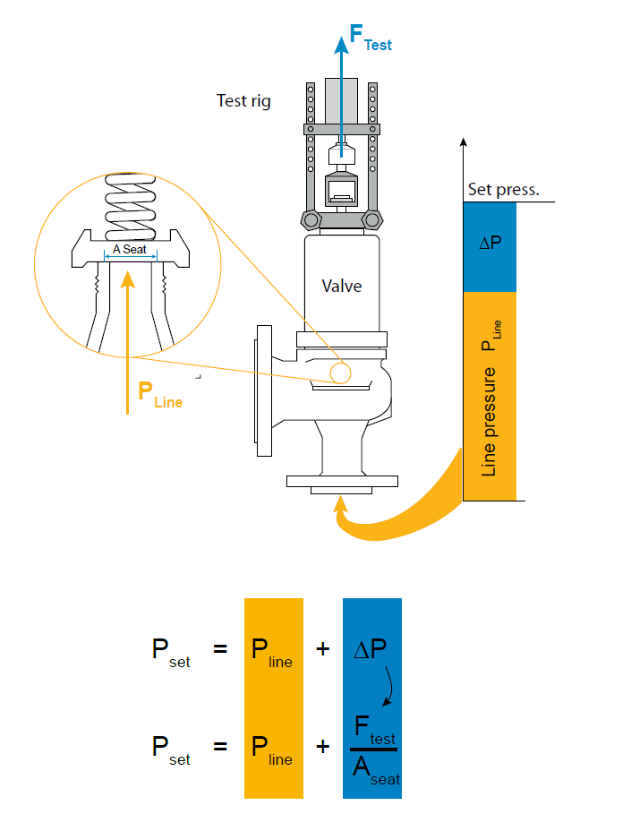
A safety valve must always be sized and able to vent any source of steam so that the pressure within the protected apparatus cannot exceed the maximum allowable accumulated pressure (MAAP). This not only means that the valve has to be positioned correctly, but that it is also correctly set. The safety valve must then also be sized correctly, enabling it to pass the required amount of steam at the required pressure under all possible fault conditions.
Once the type of safety valve has been established, along with its set pressure and its position in the system, it is necessary to calculate the required discharge capacity of the valve. Once this is known, the required orifice area and nominal size can be determined using the manufacturer’s specifications.
In order to establish the maximum capacity required, the potential flow through all the relevant branches, upstream of the valve, need to be considered.
In applications where there is more than one possible flow path, the sizing of the safety valve becomes more complicated, as there may be a number of alternative methods of determining its size. Where more than one potential flow path exists, the following alternatives should be considered:
This choice is determined by the risk of two or more devices failing simultaneously. If there is the slightest chance that this may occur, the valve must be sized to allow the combined flows of the failed devices to be discharged. However, where the risk is negligible, cost advantages may dictate that the valve should only be sized on the highest fault flow. The choice of method ultimately lies with the company responsible for insuring the plant.
For example, consider the pressure vessel and automatic pump-trap (APT) system as shown in Figure 9.4.1. The unlikely situation is that both the APT and pressure reducing valve (PRV ‘A’) could fail simultaneously. The discharge capacity of safety valve ‘A’ would either be the fault load of the largest PRV, or alternatively, the combined fault load of both the APT and PRV ‘A’.
This document recommends that where multiple flow paths exist, any relevant safety valve should, at all times, be sized on the possibility that relevant upstream pressure control valves may fail simultaneously.
The supply pressure of this system (Figure 9.4.2) is limited by an upstream safety valve with a set pressure of 11.6 bar g. The fault flow through the PRV can be determined using the steam mass flow equation (Equation 3.21.2):
Once the fault load has been determined, it is usually sufficient to size the safety valve using the manufacturer’s capacity charts. A typical example of a capacity chart is shown in Figure 9.4.3. By knowing the required set pressure and discharge capacity, it is possible to select a suitable nominal size. In this example, the set pressure is 4 bar g and the fault flow is 953 kg/h. A DN32/50 safety valve is required with a capacity of 1 284 kg/h.
Coefficients of discharge are specific to any particular safety valve range and will be approved by the manufacturer. If the valve is independently approved, it is given a ‘certified coefficient of discharge’.
This figure is often derated by further multiplying it by a safety factor 0.9, to give a derated coefficient of discharge. Derated coefficient of discharge is termed Kdr= Kd x 0.9
Critical and sub-critical flow - the flow of gas or vapour through an orifice, such as the flow area of a safety valve, increases as the downstream pressure is decreased. This holds true until the critical pressure is reached, and critical flow is achieved. At this point, any further decrease in the downstream pressure will not result in any further increase in flow.
A relationship (called the critical pressure ratio) exists between the critical pressure and the actual relieving pressure, and, for gases flowing through safety valves, is shown by Equation 9.4.2.
Overpressure - Before sizing, the design overpressure of the valve must be established. It is not permitted to calculate the capacity of the valve at a lower overpressure than that at which the coefficient of discharge was established. It is however, permitted to use a higher overpressure (see Table 9.2.1, Module 9.2, for typical overpressure values). For DIN type full lift (Vollhub) valves, the design lift must be achieved at 5% overpressure, but for sizing purposes, an overpressure value of 10% may be used.
For liquid applications, the overpressure is 10% according to AD-Merkblatt A2, DIN 3320, TRD 421 and ASME, but for non-certified ASME valves, it is quite common for a figure of 25% to be used.
Two-phase flow - When sizing safety valves for boiling liquids (e.g. hot water) consideration must be given to vaporisation (flashing) during discharge. It is assumed that the medium is in liquid state when the safety valve is closed and that, when the safety valve opens, part of the liquid vaporises due to the drop in pressure through the safety valve. The resulting flow is referred to as two-phase flow.
The required flow area has to be calculated for the liquid and vapour components of the discharged fluid. The sum of these two areas is then used to select the appropriate orifice size from the chosen valve range. (see Example 9.4.3)

A valve is a mechanical device that controls the flow of fluid and pressure within a system or process. A valve controls system or process fluid flow and pressure by performing any of the following functions:Stopping and starting fluid flow
There are many valve designs and types that satisfy one or more of the functions identified above. A multitude of valve types and designs safely accommodate a wide variety of industrial applications.
Regardless of type, all valves have the following basic parts: the body, bonnet, trim (internal elements), actuator, and packing. The basic parts of a valve are illustrated in Figure 1.
The body, sometimes called the shell, is the primary pressure boundary of a valve. It serves as the principal element of a valve assembly because it is the framework that holds everything together.
The body, the first pressure boundary of a valve, resists fluid pressure loads from connecting piping. It receives inlet and outlet piping through threaded, bolted, or welded joints.
Valve bodies are cast or forged into a variety of shapes. Although a sphere or a cylinder would theoretically be the most economical shape to resist fluid pressure when a valve is open, there are many other considerations. For example, many valves require a partition across the valve body to support the seat opening, which is the throttling orifice. With the valve closed, loading on the body is difficult to determine. The valve end connections also distort loads on a simple sphere and more complicated shapes. Ease of manufacture, assembly, and costs are additional important considerations. Hence, the basic form of a valve body typically is not spherical, but ranges from simple block shapes to highly complex shapes in which the bonnet, a removable piece to make assembly possible, forms part of the pressure-resisting body.
Narrowing of the fluid passage (venturi effect) is also a common method for reducing the overall size and cost of a valve. In other instances, large ends are added to the valve for connection into a larger line.
The cover for the opening in the valve body is the bonnet. In some designs, the body itself is split into two sections that bolt together. Like valve bodies, bonnets vary in design. Some bonnets function simply as valve covers, while others support valve internals and accessories such as the stem, disk, and actuator.
The bonnet is the second principal pressure boundary of a valve. It is cast or forged of the same material as the body and is connected to the body by a threaded, bolted, or welded joint. In all cases, the attachment of the bonnet to the body is considered a pressure boundary. This means that the weld joint or bolts that connect the bonnet to the body are pressure-retaining parts.
Valve bonnets, although a necessity for most valves, represent a cause for concern. Bonnets can complicate the manufacture of valves, increase valve size, represent a significant cost portion of valve cost, and are a source for potential leakage.
The internal elements of a valve are collectively referred to as a valve’s trim. The trim typically includes a disk, seat, stem, and sleeves needed to guide the stem. A valve’s performance is determined by the disk and seat interface and the relation of the disk position to the seat.
For a valve having a bonnet, the disk is the third primary principal pressure boundary. The disk provides the capability for permitting and prohibiting fluid flow. With the disk closed, full system pressure is applied across the disk if the outlet side is depressurized. For this reason, the disk is a pressure-retaining part. Disks are typically forged and, in some designs, hard-surfaced to provide good wear characteristics. A fine surface finish of the seating area of a disk is necessary for good sealing when the valve is closed. Most valves are named, in part, according to the design of their disks.
The seat or seal rings provide the seating surface for the disk. In some designs, the body is machined to serve as the seating surface and seal rings are not used. In other designs, forged seal rings are threaded or welded to the body to provide the seating surface. To improve the wear-resistance of the seal rings, the surface is often hard-faced by welding and then machining the contact surface of the seal ring. A fine surface finish of the seating area is necessary for good sealing when the valve is closed. Seal rings are not usually considered pressure boundary parts because the body has sufficient wall thickness to withstand design pressure without relying upon the thickness of the seal rings.
The stem, which connects the actuator and disk, is responsible for positioning the disk. Stems are typically forged and connected to the disk by threaded or welded joints. For valve designs requiring stem packing or sealing to prevent leakage, a fine surface finish of the stem in the area of the seal is necessary. Typically, a stem is not considered a pressure boundary part.
There is no upward stem movement from outside the valve for a nonrising stem design. For the nonrising stem design, the valve disk is threaded internally and mates with the stem threads.
Except for certain hydraulically controlled valves, actuators are outside of the pressure boundary. Yokes, when used, are always outside of the pressure boundary.
Most valves use some form of packing to prevent leakage from the space between the stem and the bonnet. Packing is commonly a fibrous material (such as flax) or another compound (such as teflon) that forms a seal between the internal parts of a valve and the outside where the stem extends through the body.
Valve packing must be properly compressed to prevent fluid loss and damage to the valve’s stem. If a valve’s packing is too loose, the valve will leak, which is a safety hazard. If the packing is too tight, it will impair the movement and possibly damage the stem.
Because of the diversity of the types of systems, fluids, and environments in which valves must operate, a vast array of valve types have been developed. Examples of the common types are the globe valve, gate valve, ball valve, plug valve, butterfly valve, diaphragm valve, check valve, pinch valve, and safety valve. Each type of valve has been designed to meet specific needs. Some valves are capable of throttling flow, other valve types can only stop flow, others work well in corrosive systems, and others handle high pressure fluids. Each valve type has certain inherent advantages and disadvantages. Understanding these differences and how they effect the valve’s application or operation is necessary for the successful operation of a facility.
Although all valves have the same basic components and function to control flow in some fashion, the method of controlling the flow can vary dramatically. In general, there are four methods of controlling flow through a valve.
4. Move a flexible material into the flow passage (for example, diaphragm and pinch valves).Valve stem leakage is usually controlled by properly compressing the packing around the valve stem.
A gate valve is a linear motion valve used to start or stop fluid flow; however, it does not regulate or throttle flow. The name gate is derived from the appearance of the disk in the flow stream. Figure 4 illustrates a gate valve.
The disk of a gate valve is completely removed from the flow stream when the valve is fully open. This characteristic offers virtually no resistance to flow when the valve is open. Hence, there is little pressure drop across an open gate valve.
On opening the gate valve, the flow path is enlarged in a highly nonlinear manner with respect to percent of opening. This means that flow rate does not change evenly with stem travel. Also, a partially open gate disk tends to vibrate from the fluid flow. Most of the flow change occurs near shutoff with a relatively high fluid velocity causing disk and seat wear and eventual leakage if used to regulate flow. For these reasons, gate valves are not used to regulate or throttle flow.
A gate valve can be used for a wide variety of fluids and provides a tight seal when closed. The major disadvantages to the use of a gate valve are:It is not suitable for throttling applications.
Gate valves are available with a variety of disks. Classification of gate valves is usually made by the type disk used: solid wedge, flexible wedge, split wedge, or parallel disk.
Regardless of the style of wedge or disk used, the disk is usually replaceable. In services where solids or high velocity may cause rapid erosion of the seat or disk, these components should have a high surface hardness and should have replacement seats as well as disks. If the seats are not replaceable, seat damage requires removal of the valve from the line for refacing of the seat, or refacing of the seat in place. Valves being used in corrosion service should normally be specified with replaceable seats.
The solid wedge gate valve shown in Figure 5 is the most commonly used disk because of its simplicity and strength. A valve with this type of wedge may be installed in any position and it is suitable for almost all fluids. It is practical for turbulent flow.
The flexible wedge gate valve illustrated in Figure 6 is a one-piece disk with a cut around the perimeter to improve the ability to match error or change in the angle between the seats. The cut varies in size, shape, and depth. A shallow, narrow cut gives little flexibility but retains strength. A deeper and wider cut, or cast-in recess, leaves little material at the center, which allows more flexibility but compromises strength.
Gate valves used in steam systems have flexible wedges. The reason for using a flexible gate is to prevent binding of the gate within the valve when the valve is in the closed position. When steam lines are heated, they expand and cause some distortion of valve bodies. If a solid gate fits snugly between the seat of a valve in a cold steam system, when the system is heated and pipes elongate, the seats will compress against the gate and clamp the valve shut. This problem is overcome by using a flexible gate, whose design allows the gate to flex as the valve seat compresses it.
The major problem associated with flexible gates is that water tends to collect in the body neck. Under certain conditions, the admission of steam may cause the valve body neck to rupture, the bonnet to lift off, or the seat ring to collapse. Following correct warming procedures prevent these problems.
Split wedge gate valves, as shown in Figure 7, are of the ball and socket design. These are self-adjusting and self-aligning to both seating surfaces. The disk is free to adjust itself to the seating surface if one-half of the disk is slightly out of alignment because of foreign matter lodged between the disk half and the seat ring. This type of wedge is suitable for handling non-condensing gases and liquids at normal temperatures, particularly corrosive liquids. Freedom of movement of the disk in the carrier prevents binding even though the valve may have been closed when hot and later contracted due to cooling. This type of valve should be installed with the stem in the vertical position.
The parallel disk gate valve illustrated in Figure 8 is designed to prevent valve binding due to thermal transients. This design is used in both low and high pressure applications.
The wedge surfaces between the parallel face disk halves are caused to press together under stem thrust and spread apart the disks to seal against the seats. The tapered wedges may be part of the disk halves or they may be separate elements. The lower wedge may bottom out on a rib at the valve bottom so that the stem can develop seating force. In one version, the wedge contact surfaces are curved to keep the point of contact close to the optimum.
Some parallel disk gate valves used in high pressure systems are made with an integral bonnet vent and bypass line. A three-way valve is used to position the line to bypass in order to equalize pressure across the disks prior to opening. When the gate valve is closed, the three-way valve is positioned to vent the bonnet to one side or the other. This prevents moisture from accumulating in the bonnet. The three-way valve is positioned to the high pressure side of the gate valve when closed to ensure that flow does not bypass the isolation valve. The high pressure acts against spring compression and forces one gate off of its seat. The three-way valve vents this flow back to the pressure source.
Gate valves are classified as either rising stem or nonrising stem valves. For the nonrising stem gate valve, the stem is threaded on the lower end into the gate. As the hand wheel on the stem is rotated, the gate travels up or down the stem on the threads while the stem remains vertically stationary. This type valve will almost always have a pointer-type indicator threaded onto the upper end of the stem to indicate valve position. Figures 2 and 3 illustrate rising-stem gate valves and nonrising stem gate valves.
The nonrising stem configuration places the stem threads within the boundary established by the valve packing out of contact with the environment. This configuration assures that the stem merely rotates in the packing without much danger of carrying dirt into the packing from outside to inside.
Rising stem gate valves are designed so that the stem is raised out of the flowpath when the valve is open. Rising stem gate valves come in two basic designs. Some have a stem that rises through the handwheel while others have a stem that is threaded to the bonnet.
Seats for gate valves are either provided integral with the valve body or in a seat ring type of construction. Seat ring construction provides seats which are either threaded into position or are pressed into position and seal welded to the valve body. The latter form of construction is recommended for higher temperature service.
Integral seats provide a seat of the same material of construction as the valve body while the pressed-in or threaded-in seats permit variation. Rings with hard facings may be supplied for the application where they are required.
Small, forged steel, gate valves may have hard faced seats pressed into the body. In some series, this type of valve in sizes from 1/2 to 2 inches is rated for 2500 psig steam service. In large gate valves, disks are often of the solid wedge type with seat rings threaded in, welded in, or pressed in. Screwed in seat rings are considered replaceable since they may be removed and new seat rings installed.
As shown in Figure 9, the globe valve disk can be totally removed from the flowpath or it can completely close the flowpath. The essential principle of globe valve operation is the perpendicular movement of the disk away from the seat. This causes the annular space between the disk and seat ring to gradually close as the valve is closed. This characteristic gives the globe valve good throttling ability, which permits its use in regulating flow. Therefore, the globe valve may be used for both stopping and starting fluid flow and for regulating flow.
When compared to a gate valve, a globe valve generally yields much less seat leakage. This is because the disk-to-seat ring contact is more at right angles, which permits the force of closing to tightly seat the disk.
Globe valves can be arranged so that the disk closes against or in the same direction of fluid flow. When the disk closes against the direction of flow, the kinetic energy of the fluid impedes closing but aids opening of the valve. When the disk closes in the same direction of flow, the kinetic energy of the fluid aids closing but impedes opening. This characteristic is preferable to other designs when quick-acting stop valves are necessary.
Globe valves also have drawbacks. The most evident shortcoming of the simple globe valve is the high head loss from two or more right angle turns of flowing fluid. Obstructions and discontinuities in the flowpath lead to head loss. In a large high pressure line, the fluid dynamic effects from pulsations, impacts, and pressure drops can damage trim, stem packing, and actuators. In addition, large valve sizes require considerable power to operate and are especially noisy in high pressure applications.
Other drawbacks of globe valves are the large openings necessary for disk assembly, heavier weight than other valves of the same flow rating, and the cantilevered mounting of the disk to the stem.
The simplest design and most common for water applications is the Z-body. The Z-body is illustrated in Figure 9. For this body design, the Z-shaped diaphragm or partition across the globular body contains the seat. The horizontal setting of the seat allows the stem and disk to travel at right angles to the pipe axis. The stem passes through the bonnet which is attached to a large opening at the top of the valve body. This provides a symmetrical form that simplifies manufacture, installation, and repair.
Figure 10 illustrates a typical Y-body globe valve. This design is a remedy for the high pressure drop inherent in globe valves. The seat and stem are angled at approximately 45°. The angle yields a straighter flowpath (at full opening) and provides the stem, bonnet, and packing a relatively pressureresistant envelope.
Y-body globe valves are best suited for high pressure and other severe services. In small sizes for intermittent flows, the pressure loss may not be as important as the other considerations favoring the Y-body design. Hence, the flow passage of small Y-body globe valves is not as carefully streamlined as that for larger valves.
The angle body globe valve design, illustrated in Figure 11, is a simple modification of the basic globe valve. Having ends at right angles, the diaphragm can be a simple flat plate. Fluid is able to flow through with only a single 90° turn and discharge downward more symmetrically than the discharge from an ordinary globe. A particular advantage of the angle body design is that it can function as both a valve and a piping elbow.
For moderate conditions of pressure, temperature, and flow, the angle valve closely resembles the ordinary globe. The angle valve’s discharge conditions are favorable with respect to fluid dynamics and erosion.
The composition disk design uses a hard, nonmetallic insert ring on the disk. The insert ring creates a tighter closure. Composition disks are primarily used in steam and hot water applications. They resist erosion and are sufficiently resilient to close on solid particles without damaging the valve. Composition disks are replaceable.
Globe valves employ two methods for connecting disk and stem: T-slot construction and disk nut construction. In the T-slot design, the disk slips over the stem. In the disk nut design, the disk is screwed into the stem.
Globe valve seats are either integral with or screwed into the valve body. Many globe valves have backseats. A backseat is a seating arrangement that provides a seal between the stem and bonnet. When the valve is fully open, the disk seats against the backseat. The backseat design prevents system pressure from building against the valve packing.
For low temperature applications, globe and angle valves are ordinarily installed so that pressure is under the disk. This promotes easy operation, helps protect the packing, and eliminates a certain amount of erosive action to the seat and disk faces. For high temperature steam service, globe valves are installed so that pressure is above the disk. Otherwise, the stem will contract upon cooling and tend to lift the disk off the seat.
A ball valve is a rotational motion valve that uses a ball-shaped disk to stop or start fluid flow. The ball, shown in Figure 12, performs the same function as the disk in the globe valve. When the valve handle is turned to open the valve, the ball rotates to a point where the hole through the ball is in line with the valve body inlet and outlet. When the valve is shut, the ball is rotated so that the hole is perpendicular to the flow openings of the valve body and the flow is stopped.
Most ball valve actuators are of the quick-acting type, which require a 90° turn of the valve handle to operate the valve. Other ball valve actuators are planetary gear-operated. This type of gearing allows the use of a relatively small handwheel and operating force to operate a fairly large valve.
A ball valve is generally the least expensive of any valve configuration and has low maintenance costs. In addition to quick, quarter turn on-off operation, ball valves are compact, require no lubrication, and give tight sealing with low torque.
Conventional ball valves have relatively poor throttling characteristics. In a throttling position, the partially exposed seat rapidly erodes because of the impingement of high velocity flow.
Ball valves are available in the venturi, reduced, and full port pattern. The full port pattern has a ball with a bore equal to the inside diameter of the pipe.
The resilient seats for ball valves are made from various elastomeric material. The most common seat materials are teflon (TFE), filled TFE, Nylon, Buna-N, Neoprene, and combinations of these materials. Because of the elastomeric materials, these valves cannot be used at elevated temperatures. Care must be used in the selection of the seat material to ensure that it is compatible with the materials being handled by the valve.
The stem in a ball valve is not fastened to the ball. It normally has a rectangular portion at the ball end which fits into a slot cut into the ball. The enlargement permits rotation of the ball as the stem is turned.
A bonnet cap fastens to the body, which holds the stem assembly and ball in place. Adjustment of the bonnet cap permits compression of the packing, which supplies the stem seal. Packing for ball valve stems is usually in the configuration of die-formed packing rings normally of TFE, TFE-filled, or TFE-impregnated material. Some ball valve stems are sealed by means of O-rings rather than packing.
Some ball valves are equipped with stops that permit only 90° rotation. Others do not have stops and may be rotated 360°. With or without stops, a 90° rotation is all that is required for closing or opening a ball valve.
The handle indicates valve ball position. When the handle lies along the axis of the valve, the valve is open. When the handle lies 90° across the axis of the valve, the valve is closed. Some ball valve stems have a groove cut in the top face of the stem that shows the flowpath through the ball. Observation of the groove position indicates the position of the port through the ball. This feature is particularly advantageous on multiport ball valves.
In the open position, the passage in the plug lines up with the inlet and outlet ports of the valve Figure 13 Plug Valve body. When the plug is turned 90° from the open position, the solid part of the plug blocks the ports and stops fluid flow.
Plug valves are available in either a lubricated or nonlubricated design and with a variety of styles of port openings through the plug as well as a number of plug designs.
An important characteristic of the plug valve is its easy adaptation to multiport construction. Multiport valves are widely used. Their installation simplifies piping, and they provide a more convenient operation than multiple gate valves. They also eliminate pipe fittings. The use of a multiport valve, depending upon the number of ports in the plug valve, eliminates the need of as many as four conventional shutoff valves.
Plug valves are normally used in non-throttling, on-off operations, particularly where frequent operation of the valve is necessary. These valves are not normally recommended for throttling service because, like the gate valve, a high percentage of flow change occurs near shutoff at high velocity. However, a diamond-shaped port has been developed for throttling service.
Multiport valves are particularly advantageous on transfer lines and for diverting services. A single multiport valve may be installed in lieu of three or four gate valves or other types of shutoff valve. A disadvantage is that many multiport valve configurations do not completely shut off flow.
In most cases, one flowpath is always open. These valves are intended to divert the flow of one line while shutting off flow from the other lines. If complete shutoff of flow is a requirement, it is necessary that a style of multiport valve be used that permits this, or a secondary valve should be installed on the main line ahead of the multiport valve to permit complete shutoff of flow.
Round port plug is a term that describes a valve that has a round opening through the plug. If the port is the same size or larger than the pipe’s inside diameter, it is referred to as a full port. If the opening is smaller than the pipe’s inside diameter, the port is referred to as a standard round port. Valves having standard round ports are used only where restriction of flow is unimportant.
A diamond port plug has a diamond-shaped port through the plug. This design is for throttling service. All diamond port valves are venturi restricted flow type.
Clearances and leakage prevention are the chief considerations in plug valves. Many plug valves are of all metal construction. In these versions, the narrow gap around the plug can allow leakage. If the gap is reduced by sinking the taper plug deeper into the body, actuation torque climbs rapidly and galling can occur. To remedy this condition, a series of grooves around the body and plug port openings is supplied with grease prior to actuation. Applying grease lubricates the plug motion and seals the gap between plug and body. Grease injected into a fitting at the top of the stem travels down through a check valve in the passageway, past the plug top to the grooves on the plug, and down to a well below the plug. The lubricant must be compatible with the temperature and nature of the fluid. All manufacturers of lubricated plug valves have developed a series of lubricants that are compatible with a wide range of media. Their recommendation should be followed as to which lubricant is best suited for the service.
The most common fluids controlled by plug valves are gases and liquid hydrocarbons. Some water lines have these valves, provided that lubricant contamination is not a serious danger. Lubricated plug valves may be as large as 24 inches and have pressure capabilities up to 6000 psig. Steel or iron bodies are available. The plug can be cylindrical or tapered.
There are two basic types of nonlubricated plug valves: lift-type and elastomer sleeve or plug coated. Lift-type valves provide a means of mechanically lifting the tapered plug slightly to disengage it from the seating surface to permit easy rotation. The mechanical lifting can be accomplished with a cam or external lever.
In a common, nonlubricated, plug valve having an elastomer sleeve, a sleeve of TFE completely surrounds the plug. It is retained and locked in place by a metal body. This design results in a primary seal being maintained between the sleeve and the plug at all times regardless of position. The TFE sleeve is durable and inert to all but a few rarely encountered chemicals. It also has a low coefficient of friction and is, therefore, self-lubricating.
When installing plug valves, care should be taken to allow room for the operation of the handle, lever, or wrench. The manual operator is usually longer than the valve, and it rotates to a position parallel to the pipe from a position 90° to the pipe.
The gland of the plug valve is equivalent to the bonnet of a gate or globe valve. The gland secures the stem assembly to the valve body. There are three general types of glands: single gland, screwed gland, and bolted gland.
To ensure a tight valve, the plug must be seated at all times. Gland adjustment should be kept tight enough to prevent the plug from becoming unseated and exposing the seating surfaces to the live fluid. Care should be exercised to not overtighten the gland, which will result in a metal-to-metal contact between the body and the plug. Such a metal-to-metal contact creates an additional force which will require extreme effort to operate the valve.
Diaphragm valves are, in effect, simple “pinch clamp” valves. A resilient, flexible diaphragm is connected to a compressor by a stud molded into the diaphragm. The compressor is moved up and down by the valve stem. Hence, the diaphragm lifts when the compressor is raised. As the compressor is lowered, the diaphragm is pressed against the contoured bottom in the straight through valve illustrated in Figure 14 or the body weir in the weir-type valve illustrated in Figure 15
Diaphragm valves can also be used for throttling service. The weir-type is the better throttling valve but has a limited range. Its throttling characteristics are essentially those of a quickopening valve because of the large shutoff area along the seat.
A weir-type diaphragm valve is available to control small flows. It uses a two-piece compressor component. Instead of the entire diaphragm lifting off the weir when the valve is opened, the first increments of stem travel raise an inner compressor component that causes only the central part of the diaphragm to lift. This creates a relatively small opening through the center of the valve. After the inner compressor is completely open, the outer compressor component is raised along with the inner compressor and the remainder of the throttling is similar to the throttling that takes place in a conventional valve.
Diaphragm valves are particularly suited for the handling of corrosive fluids, fibrous slurries, radioactive fluids, or other fluids that must remain free from contamination.
The operating mechanism of a diaphragm valve is not exposed to the media within the pipeline. Sticky or viscous fluids cannot get into the bonnet to interfere with the operating mechanism. Many fluids that would clog, corrode, or gum up the working parts of most other types of valves will pass through a diaphragm valve without causing problems. Conversely, lubricants used for the operating mechanism cannot be allowed to contaminate the fluid being handled. There are no packing glands to maintain and no possibility of stem leakage. There is a wide choice of available diaphragm materials. Diaphragm life depends upon the nature of the material handled, temperature, pressure, and frequency of operation.
Diaphragm valves have stems that do not rotate. The valves are available with indicating and nonindicating stems. The indicating stem valve is identical to the nonindicating stem valve except that a longer stem is provided to extend up through the handwheel. For the nonindicating stem design, the handwheel rotates a stem bushing that engages the stem threads and moves the stem up and down. As the stem moves, so does the compressor that is pinned to the stem. The diaphragm, in turn, is secured to the compressor.
Some diaphragm valves use a quick-opening bonnet and lever operator. This bonnet is interchangeable with the standard bonnet on conventional weir-type bodies. A 90° turn of the lever moves the diaphragm from full open to full closed. Diaphragm valves may also be equipped with chain wheel operators, extended stems, bevel gear operators, air operators, and hydraulic operators.
Many diaphragm valves are used in vacuum service. Standard bonnet construction can be employed in vacuum service through 4 inches in size. On valves 4 inches and larger, a sealed, evacuated, bonnet should be employed. This is recommended to guard against premature diaphragm failure.
Sealed bonnets are supplied with a seal bushing on the nonindicating types and a seal bushing plus O-ring on the indicating types. Construction of the bonnet assembly of a diaphragm valve is illustrated in Figure 15. This design is recommended for valves that are handling dangerous liquids and gases. In the event of a diaphragm failure, the hazardous materials will not be released to the atmosphere. If the materials being handled are extremely hazardous, it is recommended that a means be provided to permit a safe disposal of the corrodents from the bonnet.
Reducing valve operation is controlled by high pressure at the valve inlet and the adjusting screw on top of the valve assembly. The pressure entering the main valve assists the main valve spring in keeping the reducing valve closed by pushing upward on the main valve disk. However, some of the high pressure is bled to an auxiliary valve on top of the main valve. The auxiliary valve controls the admission of high pressure to the piston on top of the main valve. The piston has a larger surface area than the main valve disk, resulting in a net downward force to open the main valve. The auxiliary valve is controlled by a controlling diaphragm located directly over the auxiliary valve.
The controlling diaphragm transmits a downward force that tends to open the auxiliary valve. The downward force is exerted by the adjusting spring, which is controlled by the adjusting screw. Reduced pressure from the main valve outlet is bled back to a chamber beneath the diaphragm to counteract the downward force of the adjusting spring. The position of the auxiliary valve, and ultimately the position of the main valve, is determined by the position of the diaphragm. The position of the diaphragm is determined by the strength of the opposing forces of the downward force of the adjusting spring versus the upward force of the outlet reduced pressure. Other reducing valves work on the same basic principle, but may use gas, pneumatic, or hydraulic controls in place of the adjusting spring and screw.
Non-variable reducing valves eliminate the need for the intermediate auxiliary valve found in variable reducing valves by having the opposing forces react directly on the diaphragm. Therefore, non-variable reducing valves are more responsive to large pressure variations and are less susceptible to failure than are variable reducing valves.
The relatively inexpensive pinch valve, Figure 18 Pinch Valves illustrated in Figure 18, is the simplest in any valve design. It is simply an industrial version of the pinch cock used in the laboratory to control the flow of fluids through rubber tubing.
Pinch valves are suitable for on-off and throttling services. However, the effective throttling range is usually between 10% and 95% of the rated flow capacity.
Pinch valves are ideally suited for the handling of slurries, liquids with large amounts of suspended solids, and systems that convey solids pneumatically. Because the operating mechanism is completely isolated from the fluid, these valves also find application where corrosion or metal contamination of the fluid might be a problem.
The pinch control valve consists of a sleeve molded of rubber or other synthetic material and a pinching mechanism. All of the operating portions are completely external to the valve. The molded sleeve is referred to as the valve body.
Pinch valve bodies are manufactured of natural and synthetic rubbers and plastics which have good abrasion resistance properties. These properties permit little damage to the valve sleeve, thereby providing virtually unimpeded flow. Sleeves are available with either extended hubs and clamps designed to slip over a pipe end, or with a flanged end having standard dimensions.
Pinch valves have molded bodies reinforced with fabric. Pinch valves generally have a maximum operating temperature of 250o F. At 250o F, maximum operating pressure varies generally from 100 psig for a 1-inch diameter valve and decreases to 15 psig for a 12-inch diameter valve. Special pinch valves are available for temperature ranges of -100o F to 550o F and operating pressures of 300 psig.
Most pinch valves are supplied with the sleeve (valve body) exposed. Another style fully encloses the sleeve within a metallic body. This type controls flow either with the conventional wheel and screw pinching device, hydraulically, or pneumatically with the pressure of the liquid or gas within the metal case forcing the sleeve walls together to shut off flow.
Most exposed sleeve valves have limited vacuum application because of the tendency of the sleeves to collapse when vacuum is applied. Some of the encased valves can be used on vacuum service by applying a vacuum within the metal casing and thus preventing the collapse of the sleeve.
A butterfly valve, illustrated in Figure 19, is a rotary motion valve that is used to stop, regulate, and start fluid flow. Butterfly valves are easily and quickly operated because a 90o rotation of the handle moves the disk from a fully closed to fully opened position. Larger butterfly valves are actuated by handwheels connected to the stem through gears that provide mechanical advantage at the expense of speed.
Butterfly valves possess many advantages over gate, globe, plug, and ball valves, especially for large valve applications. Savings in weight, space, and cost are the most obvious advantages. The maintenance costs are usually low because there are a minimal number of moving parts and there are no pockets to trap fluids.
Butterfly valves are especially well-suited for the handling of large flows of liquids or gases at relatively low pressures and for the handling of slurries or liquids with large amounts of suspended solids.
Butterfly valves are built on the principle of a pipe damper. The flow control element is a disk of approximately the same diameter as the inside diameter of the adjoining pipe, which rotates on either a vertical or horizontal axis. When the disk lies parallel to the piping run, the valve is fully opened. When the disk approaches the perpendicular position, the valve is shut. Intermediate positions, for throttling purposes, can be secured in place by handle-locking devices.
Stoppage of flow is accomplished by the valve disk sealing against a seat that is on the inside diameter periphery of the valve body. Many butterfly valves have an elastomeric seat against which the disk seals. Other butterfly valves have a seal ring arrangement that uses a clamp-ring and backing-ring on a serrated edged rubber ring. This design prevents extrusion of the O-rings. In early designs, a metal disk was used to seal against a metal seat. This arrangement did not provide a leak-tight closure, but did provide sufficient closure in some applications (i.e., water distribution lines).
Butterfly valve body construction varies. The most economical is the wafer type that fits between two pipeline flanges. Another type, the lug wafer design, is held in place between two pipe flanges by bolts that join the two flanges and pass through holes in the valve’s outer casing. Butterfly valves are available with conventional flanged ends for bolting to pipe flanges, and in a threaded end construction.
The stem and disk for a butterfly valve are separate pieces. The disk is bored to receive the stem. Two methods are used to secure the disk to the stem so that the disk rotates as the stem is turned. In the first method, the disk is bored through and secured to the stem with bolts or pins. The alternate method involves boring the disk as before, then shaping the upper stem bore to fit a squared or hex-shaped stem. This method allows the disk to “float” and seek its center in the seat. Uniform sealing is accomplished and external stem fasteners are eliminated. This method of assembly is advantageous in the case of covered disks and in corrosive applications.
In order for the disk to be held in the proper position, the stem must extend beyond the bottom of the disk and fit into a bushing in the bottom of the valve body. One or two similar bushings are along the upper portion of the stem as well. These bushings must be either resistant to the media being handled or sealed so that the corrosive media cannot come into contact with them.
Stem seals are accomplished either with packing in a conventional stuffing box or by means of O-ring seals. Some valve manufacturers, particularly those specializing in the handling of corrosive materials, place a stem seal on the inside of the valve so that no material being handled by the valve can come into contact with the valve stem. If a stuffing box or external O-ring is employed, the fluid passing through the valve will come into contact with the valve stem.
The distinguishing characteristic of a needle valve is the long, tapered, needlelike point on the end of the valve stem. This “needle” acts as a disk. The longer part of the needle is smaller than the orifice in the valve seat and passes through the orifice before the needle seats. This arrangement permits a very gradual increase or decrease in the size of the opening. Needle valves are often used as component parts of other, more complicated valves. For example, they are used in some types of reducing valves.
Most constant pressure pump governors have needle valves to minimize the effects of fluctuations in pump discharge pressure. Needle valves are also used in some components of automatic combustion control systems where very precise flow regulation is necessary.
Needle valves are frequently used as metering valves. Metering valves are used for extremely fine flow control. The thin disk or orifice allows for linear flow characteristics. Therefore, the number of hand wheel turns can be directly correlated to the amount of flow. A typical metering valve has a stem with 40 threads per inch.
Needle valves generally use one of two styles of stem packing: an O-ring with TFE backing rings or a TFE packing cylinder. Needle valves are often equipped with replaceable seats for ease of maintenance.
Check valves are designed to prevent the reversal of flow in a piping system. These valves are activated by the flowing material in the pipeline. The pressure of the fluid passing through the system opens the valve, while any reversal of flow will close the valve. Closure is accomplished by the weight of the check mechanism, by back pressure, by a spring, or by a combination of these means. The general types of check valves are swing, tilting-disk, piston, butterfly, and stop.
A swing check valve is normally recommended for use in systems employing gate valves because Figure 22 Swing Check Valve of the low pressure drop across the valve. Swing check valves are available in either Y-pattern or straight body design. A straight check valve is illustrated in Figure 22. In either style, the disk and hinge are suspended from the body by means of a hinge pin. Seating is either metal-tometal or metal seat to composition disk. Composition disks are usually recommended for services where dirt or other particles may be present in the fluid, where noise is objectionable, or where positive shutoff is required.
Straight body swing check valves contain a disk that is hinged at the top. The disk seals against the seat, which is integral with the body. This type of check valve usually has replaceable seat rings. The seating surface is placed at a slight angle to permit easier opening at lower pressures, more positive sealing, and less shock when closing under higher pressures.
Swing check valves are usually installed in conjunction with gate valves because they provide relatively free flow. They are recommended for lines having low velocity flow and should not be used on lines with pulsating flow when the continual flapping or pounding would be destructive to the seating elements. This condition can be partially corrected by using an external lever and weight.
Tilting disk check valves can be installed in horizontal lines and vertical lines having upward Figure 23 Operation of Tilting Disk Check Valve flow. Some designs simply fit between two flange faces and provide a compact, lightweight installation, particularly in larger diameter valves.
The disk lifts off of the seat to open the valve. The airfoil design of the disk allows it to “float” on the flow. Disk stops built into the body position the disk for optimum flow characteristics. A large body cavity helps minimize flow restriction. As flow decreases, the disk starts closing and seals before reverse flow occurs. Backpressure against the disk moves it across the soft seal into the metal seat for tight shutoff without slamming. If the reverse flow pressure is insufficient to cause a tight seal, the valve may be fitted with an external lever and weight.
These valves are available with a soft seal ring, metal seat seal, or a metal-to-metal seal. The latter is recommended for high temperature operation. The soft seal rings are replaceable, but the valve must be removed from the line to make the replacement.
A lift check valve, illustrated in Figure 24, is commonly used in piping systems in which globe valves are being used as a flow control valve. They have similar seating arrangements as globe valves.
Flow to lift check valves must always enter below


 8613371530291