
speed safety valve brands

The RV10 safety relief valve is well-suited for overpressure protection of production equipment, including compressors, scrubbers, separators, pipelines or anywhere overpressure protection may be required.

Of all the challenges you face keeping your customers’ plants operating at full capacity, safety and relief valves shouldn’t be one of them. NASVI’s job is to give you the confidence that your valve supply chain is rock solid regardless the pressure it’s under.

We’ve got your back. Let us find the exact part you’re looking for in our 100,000 sq. ft. warehouse stocked with 35,000 ready-to-ship valves from the world’s most renowned brands. We’ll put our decades of experiencing cross-referencing valves to work fast. Just give us a call.
Industry leading pressure and safety relief valve designs with over 140 years of technical and application expertise providing custom engineered solutions for O&G, Refining, Chemical, Petrochemical, Process and Power applications. Our designs meet global and local codes and standards (API 526; ASME Section I, IV & VIII; EN ISO 4126; PED & more). Gain insight into the performance of your pressure relief valves with wireless monitoring.

Safety valves play an important role in keeping people and equipment safe. Building on the long legacy of the Consolidated Safety Valves, we work closely with customers and regulatory organizations to configure, engineer, and manufacture safety valves that can help maintain safer operating conditions in a full range of environments.
Our safety valves comply with the ASME Section I code for boiler applications. They are built with many features that meet ASME requirements for steam-compressible fluids. Baker Hughes’s Consolidated safety valves are known for exceptional quality, performance and dependability. It is important they are reliable even the in most demanding real-world applications. With a range of styles, models, options and configurations, our safety valves work in many different applications.
Not sure which valve you need for your application?Download ValSpeQ (Mooney regulators & Becker valves) or ValvStream™ (Masoneilan and Consolidated valves) to size, select and generate proposal documentation for your valves.
Consolidated Green Tag Centers (GTC) comprise one of the broadest OEM service networks in the industry. With more than 80 facilities located in more than 30 countries worldwide, the GTCNet™ network provides the aftermarket support you need. Our GTC customers receive responsive and effective service through OEM-certified repairs, innovative valve diagnostics from ValvKeep™- valve management and maintenance software, and the EVT-Pro, an electronic valve testing device. Each GTC location is staffed with highly qualified technicians, specifically trained and certified to deliver exceptional product support and technical expertise.

In the oil and gas industry, fluid system equipment downtime can be extraordinarily costly. Some facilities may even lose up to $100,000 an hour due to equipment failure. Charbonneau Industries’ unique stocking strategy enables an uncommon responsiveness few companies can match—with a production speed empowered by Swagelok® Custom Solutions.
Charbonneau Industries’ strategic decision to use Swagelok Custom Solutions has allowed the company to focus heavily on its business model and value-added capabilities. By speeding the production process, the Texas-based company has in turn reduced overall labor costs.
“Right now, Swagelok is fabricating a differential thermal relief valves (DTRs) system for the company,” says Jones. “Many of the valves that Charbonneau Industries puts together has DTRs on them. Providing these Swagelok Custom Solutions has saved them a lot of time. Their employees no longer have to build these specific assemblies that may take them up to two hours to complete, saving them a significant amount of time per valve.”
In the oil and gas industry, safety is critical. Natural gas runs through miles and miles of pipelines—through cities, along interstates, in houses and everywhere in between. It’s necessary to ensure oil and gas systems are safe and running at all times.
“A lot of our products go into critical applications such as shut-down valves,” Hamilton states. “If these components don’t work when they are supposed to, then that station won’t be able to come offline—potentially impacting the flow down the line.”
“I trust Swagelok because they’re the best,” Curtis Butts, supervisor at Charbonneau Industries states proudly. “I don’t have to question whether or not a Swagelok component is going to work two years, or even ten years, down the road. I’ve seen Swagelok products come back on our actuators and valves that were installed 20 years ago and they’re still holding pressure just fine.”
Swagelok customized fluid system assemblies allowed Charbonneau Industries to focus on its strategic business model all while speeding production and securing system reliability demanded by customers. Want to learn how Swagelok Custom Solutions can develop a system configuration right for you? Contact your local nearest sales and service center to request more information.
Headquartered in Houston, Texas, Charbonneau Industries is a brand-neutral master distributor and integrated supplier of engineered products and systems for a range of major industries, including the global oil and gas industry. The company’s focus on quality and responsive speed through a unique inventory strategy has propelled Charbonneau Industries’ rapid growth.

R series proportional relief valves provide simple, reliable, overpressure protection for a variety of liquid or gas general-industry applications with set pressures from 10 to 6000 psig (0.7 to 413 bar). They open gradually as the pressure increases and will close when the system pressure falls below the set pressure. The set pressure can be set at the factory or easily adjusted in the field. PRV series proportional safety relief valves are certified to PED 2014/68/EU Category IV, CE-marked in accordance with the Pressure Equipment Directive as a safety valve according to ISO-4126-1, and factory-set, tested, locked, and tagged with the set pressure.
Swagelok bleed valves can be used on instrumentation devices such as multivalve manifolds or gauge valves to vent signal line pressure to atmosphere before removal of an instrument or to assist in calibration of control devices. Male NPT and SAE end connections are available. Purge valves are manual bleed, vent, or drain valves with NPT, SAE, Swagelok tube fitting, or tube adapter end connections. A knurled cap is permanently assembled to the valve body for safety. Both bleed and purge valves are compact for convenient installation.

With more than 1,050 employees and 130,000 safety valves produced per year, LESER is the largest manufacturer of safety valves in Europe and one of the leading companies in its industry worldwide.
LESER offers spring loaded and pilot operated safety valves for all industrial applications according to the Pressure Equipment Directive and ASME XIII. Major companies in the chemical, oil and gas, petrochemical, energy, technical gases, LNG/LPG, pharmaceutical, food and beverage, shipbuilding and heating and air conditioning industries use LESER safety valves.
LESER safety valves are developed for the international market in Hamburg and manufactured in the modern plant in Hohenwestedt/Germany. In addition, LESER produces safety valves to the same standards in India and China for the local markets. Nine subsidiaries and offices in Europe, America, the Middle East and Asia as well as authorized contacts in over 80 countries guarantee competent customer advice and fast, reliable deliveries.

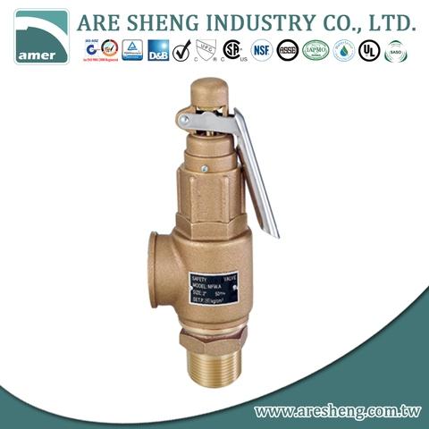
Thermoglide design improves the gliding characteristics of internal parts thus enabling the valve to achieve its full lift and re-seat point within the fastest possible time

General Pump 100723 6,000 PSI Safety Relief Valve 3/8” MPT-N with 1/4” Hose Barb. This safety relief valve is a manually adjustable pressure-operated device which, according to its setting releases the excess of water when the pressure inside the pump/system exceeds the adjusted value, thus reducing the pressure. The normal working conditions can be restored by turning off and then restarting the system

The VRC Protx service team has an industry leading safety record and is comprised of individuals including Engineers, Quality Control Foremen and Technicians who provide onsite and shop services for both planned and emergency requirements.
VRC Protx is the sales, support and service representative for Farris Pressure Relief and Safety Valves across their service and sales regions. As the local Farris representative and part of the Farris Authorized Service Team, or “FAST” Center Network, VRC Protx will provide overall life cycle management support for all pressure relief valve products. Farris’ FAST Centers provide customers with local “VR” certified service by factory-trained technicians working in independent repair, service and stocking centers. VRC Protx provides National Board qualified assembly of Farris Engineering pressure relief valve and repair services for all brands and manufacturers, including mobile units for on-site and emergency service.
With over 30 years of onsite Field Testing and Repair Experience. VRC Protx is National Board of Boiler and Pressure vessel Inspector’s Certified for “VR” repair of all Manufactures ASME Code and National Board Capacity Certified Pressure Relief Valves. Our factory trained QC Foremen and Technicians repair, functional test and document these processes using only OEM repair parts. Mobile Trailers are available for onsite services with Electronic Inline Valve Testing, (Section I and Section VIII Applications).
Through our Factory Authorized Pressure Management Center, VRC Protx maintains a local inventory of valves and parts, providing warranty service for Kunkle valves. We provide ASME and National Board Authorized Safety Relief Valve Assembly.
A safety valve must always be sized and able to vent any source of steam so that the pressure within the protected apparatus cannot exceed the maximum allowable accumulated pressure (MAAP). This not only means that the valve has to be positioned correctly, but that it is also correctly set. The safety valve must then also be sized correctly, enabling it to pass the required amount of steam at the required pressure under all possible fault conditions.
Once the type of safety valve has been established, along with its set pressure and its position in the system, it is necessary to calculate the required discharge capacity of the valve. Once this is known, the required orifice area and nominal size can be determined using the manufacturer’s specifications.
In order to establish the maximum capacity required, the potential flow through all the relevant branches, upstream of the valve, need to be considered.
In applications where there is more than one possible flow path, the sizing of the safety valve becomes more complicated, as there may be a number of alternative methods of determining its size. Where more than one potential flow path exists, the following alternatives should be considered:
This choice is determined by the risk of two or more devices failing simultaneously. If there is the slightest chance that this may occur, the valve must be sized to allow the combined flows of the failed devices to be discharged. However, where the risk is negligible, cost advantages may dictate that the valve should only be sized on the highest fault flow. The choice of method ultimately lies with the company responsible for insuring the plant.
For example, consider the pressure vessel and automatic pump-trap (APT) system as shown in Figure 9.4.1. The unlikely situation is that both the APT and pressure reducing valve (PRV ‘A’) could fail simultaneously. The discharge capacity of safety valve ‘A’ would either be the fault load of the largest PRV, or alternatively, the combined fault load of both the APT and PRV ‘A’.
This document recommends that where multiple flow paths exist, any relevant safety valve should, at all times, be sized on the possibility that relevant upstream pressure control valves may fail simultaneously.
The supply pressure of this system (Figure 9.4.2) is limited by an upstream safety valve with a set pressure of 11.6 bar g. The fault flow through the PRV can be determined using the steam mass flow equation (Equation 3.21.2):
Once the fault load has been determined, it is usually sufficient to size the safety valve using the manufacturer’s capacity charts. A typical example of a capacity chart is shown in Figure 9.4.3. By knowing the required set pressure and discharge capacity, it is possible to select a suitable nominal size. In this example, the set pressure is 4 bar g and the fault flow is 953 kg/h. A DN32/50 safety valve is required with a capacity of 1 284 kg/h.
Coefficients of discharge are specific to any particular safety valve range and will be approved by the manufacturer. If the valve is independently approved, it is given a ‘certified coefficient of discharge’.
This figure is often derated by further multiplying it by a safety factor 0.9, to give a derated coefficient of discharge. Derated coefficient of discharge is termed Kdr= Kd x 0.9
Critical and sub-critical flow - the flow of gas or vapour through an orifice, such as the flow area of a safety valve, increases as the downstream pressure is decreased. This holds true until the critical pressure is reached, and critical flow is achieved. At this point, any further decrease in the downstream pressure will not result in any further increase in flow.
A relationship (called the critical pressure ratio) exists between the critical pressure and the actual relieving pressure, and, for gases flowing through safety valves, is shown by Equation 9.4.2.
Overpressure - Before sizing, the design overpressure of the valve must be established. It is not permitted to calculate the capacity of the valve at a lower overpressure than that at which the coefficient of discharge was established. It is however, permitted to use a higher overpressure (see Table 9.2.1, Module 9.2, for typical overpressure values). For DIN type full lift (Vollhub) valves, the design lift must be achieved at 5% overpressure, but for sizing purposes, an overpressure value of 10% may be used.
For liquid applications, the overpressure is 10% according to AD-Merkblatt A2, DIN 3320, TRD 421 and ASME, but for non-certified ASME valves, it is quite common for a figure of 25% to be used.
Two-phase flow - When sizing safety valves for boiling liquids (e.g. hot water) consideration must be given to vaporisation (flashing) during discharge. It is assumed that the medium is in liquid state when the safety valve is closed and that, when the safety valve opens, part of the liquid vaporises due to the drop in pressure through the safety valve. The resulting flow is referred to as two-phase flow.
The required flow area has to be calculated for the liquid and vapour components of the discharged fluid. The sum of these two areas is then used to select the appropriate orifice size from the chosen valve range. (see Example 9.4.3)

For quadruple the fun, this tube holds up to 4 riders at a maximum weight of 680 pounds. Thanks to the speed safety valve, inflating and deflating has never been easier.


 8613371530291