
the safety valve discharges automatically at the pressure of price

With a basically fully-charged air system (within the effective operating range for the compressor), turn off the engine, release all brakes, and let the system settle (air gauge needle stops moving). Time for 1 minute. The air pressure should not drop more than:

Finding a quality driving school in can be a difficult and time consuming task. driving-schools.com comprehensive database of driving schools helps you pick one that’s right for you.

There is a wide range of safety valves available to meet the many different applications and performance criteria demanded by different industries. Furthermore, national standards define many varying types of safety valve.
The ASME standard I and ASME standard VIII for boiler and pressure vessel applications and the ASME/ANSI PTC 25.3 standard for safety valves and relief valves provide the following definition. These standards set performance characteristics as well as defining the different types of safety valves that are used:
ASME I valve - A safety relief valve conforming to the requirements of Section I of the ASME pressure vessel code for boiler applications which will open within 3% overpressure and close within 4%. It will usually feature two blowdown rings, and is identified by a National Board ‘V’ stamp.
ASME VIII valve- A safety relief valve conforming to the requirements of Section VIII of the ASME pressure vessel code for pressure vessel applications which will open within 10% overpressure and close within 7%. Identified by a National Board ‘UV’ stamp.
Full bore safety valve - A safety valve having no protrusions in the bore, and wherein the valve lifts to an extent sufficient for the minimum area at any section, at or below the seat, to become the controlling orifice.
Conventional safety relief valve -The spring housing is vented to the discharge side, hence operational characteristics are directly affected by changes in the backpressure to the valve.
Balanced safety relief valve -A balanced valve incorporates a means of minimising the effect of backpressure on the operational characteristics of the valve.
Pilot operated pressure relief valve -The major relieving device is combined with, and is controlled by, a self-actuated auxiliary pressure relief device.
Power-actuated safety relief valve - A pressure relief valve in which the major pressure relieving device is combined with, and controlled by, a device requiring an external source of energy.
Standard safety valve - A valve which, following opening, reaches the degree of lift necessary for the mass flowrate to be discharged within a pressure rise of not more than 10%. (The valve is characterised by a pop type action and is sometimes known as high lift).
Full lift (Vollhub) safety valve -A safety valve which, after commencement of lift, opens rapidly within a 5% pressure rise up to the full lift as limited by the design. The amount of lift up to the rapid opening (proportional range) shall not be more than 20%.
Direct loaded safety valve -A safety valve in which the opening force underneath the valve disc is opposed by a closing force such as a spring or a weight.
Proportional safety valve - A safety valve which opens more or less steadily in relation to the increase in pressure. Sudden opening within a 10% lift range will not occur without pressure increase. Following opening within a pressure of not more than 10%, these safety valves achieve the lift necessary for the mass flow to be discharged.
Diaphragm safety valve -A direct loaded safety valve wherein linear moving and rotating elements and springs are protected against the effects of the fluid by a diaphragm
Bellows safety valve - A direct loaded safety valve wherein sliding and (partially or fully) rotating elements and springs are protected against the effects of the fluids by a bellows. The bellows may be of such a design that it compensates for influences of backpressure.
Controlled safety valve - Consists of a main valve and a control device. It also includes direct acting safety valves with supplementary loading in which, until the set pressure is reached, an additional force increases the closing force.
Safety valve - A safety valve which automatically, without the assistance of any energy other than that of the fluid concerned, discharges a quantity of the fluid so as to prevent a predetermined safe pressure being exceeded, and which is designed to re-close and prevent further flow of fluid after normal pressure conditions of service have been restored. Note; the valve can be characterised either by pop action (rapid opening) or by opening in proportion (not necessarily linear) to the increase in pressure over the set pressure.
Direct loaded safety valve -A safety valve in which the loading due to the fluid pressure underneath the valve disc is opposed only by a direct mechanical loading device such as a weight, lever and weight, or a spring.
Assisted safety valve -A safety valve which by means of a powered assistance mechanism, may additionally be lifted at a pressure lower than the set pressure and will, even in the event of a failure of the assistance mechanism, comply with all the requirements for safety valves given in the standard.
Supplementary loaded safety valve - A safety valve that has, until the pressure at the inlet to the safety valve reaches the set pressure, an additional force, which increases the sealing force.
Note; this additional force (supplementary load), which may be provided by means of an extraneous power source, is reliably released when the pressure at the inlet of the safety valve reaches the set pressure. The amount of supplementary loading is so arranged that if such supplementary loading is not released, the safety valve will attain its certified discharge capacity at a pressure not greater than 1.1 times the maximum allowable pressure of the equipment to be protected.
Pilot operated safety valve -A safety valve, the operation of which is initiated and controlled by the fluid discharged from a pilot valve, which is itself, a direct loaded safety valve subject to the requirement of the standard.
The common characteristic shared between the definitions of conventional safety valves in the different standards, is that their operational characteristics are affected by any backpressure in the discharge system. It is important to note that the total backpressure is generated from two components; superimposed backpressure and the built-up backpressure:
Subsequently, in a conventional safety valve, only the superimposed backpressure will affect the opening characteristic and set value, but the combined backpressure will alter the blowdown characteristic and re-seat value.
The ASME/ANSI standard makes the further classification that conventional valves have a spring housing that is vented to the discharge side of the valve. If the spring housing is vented to the atmosphere, any superimposed backpressure will still affect the operational characteristics. Thiscan be seen from Figure 9.2.1, which shows schematic diagrams of valves whose spring housings are vented to the discharge side of the valve and to the atmosphere.
By considering the forces acting on the disc (with area AD), it can be seen that the required opening force (equivalent to the product of inlet pressure (PV) and the nozzle area (AN)) is the sum of the spring force (FS) and the force due to the backpressure (PB) acting on the top and bottom of the disc. In the case of a spring housing vented to the discharge side of the valve (an ASME conventional safety relief valve, see Figure 9.2.1 (a)), the required opening force is:
In both cases, if a significant superimposed backpressure exists, its effects on the set pressure need to be considered when designing a safety valve system.
Once the valve starts to open, the effects of built-up backpressure also have to be taken into account. For a conventional safety valve with the spring housing vented to the discharge side of the valve, see Figure 9.2.1 (a), the effect of built-up backpressure can be determined by considering Equation 9.2.1 and by noting that once the valve starts to open, the inlet pressure is the sum of the set pressure, PS, and the overpressure, PO.
Balanced safety valves are those that incorporate a means of eliminating the effects of backpressure. There are two basic designs that can be used to achieve this:
Although there are several variations of the piston valve, they generally consist of a piston type disc whose movement is constrained by a vented guide. The area of the top face of the piston, AP, and the nozzle seat area, AN, are designed to be equal. This means that the effective area of both the top and bottom surfaces of the disc exposed to the backpressure are equal, and therefore any additional forces are balanced. In addition, the spring bonnet is vented such that the top face of the piston is subjected to atmospheric pressure, as shown in Figure 9.2.2.
The bellows arrangement prevents backpressure acting on the upper side of the disc within the area of the bellows. The disc area extending beyond the bellows and the opposing disc area are equal, and so the forces acting on the disc are balanced, and the backpressure has little effect on the valve opening pressure.
Bellows failure is an important concern when using a bellows balanced safety valve, as this may affect the set pressure and capacity of the valve. It is important, therefore, that there is some mechanism for detecting any uncharacteristic fluid flow through the bellows vents. In addition, some bellows balanced safety valves include an auxiliary piston that is used to overcome the effects of backpressure in the case of bellows failure. This type of safety valve is usually only used on critical applications in the oil and petrochemical industries.
In addition to reducing the effects of backpressure, the bellows also serve to isolate the spindle guide and the spring from the process fluid, this is important when the fluid is corrosive.
Since balanced pressure relief valves are typically more expensive than their unbalanced counterparts, they are commonly only used where high pressure manifolds are unavoidable, or in critical applications where a very precise set pressure or blowdown is required.
This type of safety valve uses the flowing medium itself, through a pilot valve, to apply the closing force on the safety valve disc. The pilot valve is itself a small safety valve.
The diaphragm type is typically only available for low pressure applications and it produces a proportional type action, characteristic of relief valves used in liquid systems. They are therefore of little use in steam systems, consequently, they will not be considered in this text.
The piston type valve consists of a main valve, which uses a piston shaped closing device (or obturator), and an external pilot valve. Figure 9.2.4 shows a diagram of a typical piston type, pilot operated safety valve.
The piston and seating arrangement incorporated in the main valve is designed so that the bottom area of the piston, exposed to the inlet fluid, is less than the area of the top of the piston. As both ends of the piston are exposed to the fluid at the same pressure, this means that under normal system operating conditions, the closing force, resulting from the larger top area, is greater than the inlet force. The resultant downward force therefore holds the piston firmly on its seat.
If the inlet pressure were to rise, the net closing force on the piston also increases, ensuring that a tight shut-off is continually maintained. However, when the inlet pressure reaches the set pressure, the pilot valve will pop open to release the fluid pressure above the piston. With much less fluid pressure acting on the upper surface of the piston, the inlet pressure generates a net upwards force and the piston will leave its seat. This causes the main valve to pop open, allowing the process fluid to be discharged.
When the inlet pressure has been sufficiently reduced, the pilot valve will reclose, preventing the further release of fluid from the top of the piston, thereby re-establishing the net downward force, and causing the piston to reseat.
Pilot operated safety valves offer good overpressure and blowdown performance (a blowdown of 2% is attainable). For this reason, they are used where a narrow margin is required between the set pressure and the system operating pressure. Pilot operated valves are also available in much larger sizes, making them the preferred type of safety valve for larger capacities.
One of the main concerns with pilot operated safety valves is that the small bore, pilot connecting pipes are susceptible to blockage by foreign matter, or due to the collection of condensate in these pipes. This can lead to the failure of the valve, either in the open or closed position, depending on where the blockage occurs.
The terms full lift, high lift and low lift refer to the amount of travel the disc undergoes as it moves from its closed position to the position required to produce the certified discharge capacity, and how this affects the discharge capacity of the valve.
A full lift safety valve is one in which the disc lifts sufficiently, so that the curtain area no longer influences the discharge area. The discharge area, and therefore the capacity of the valve are subsequently determined by the bore area. This occurs when the disc lifts a distance of at least a quarter of the bore diameter. A full lift conventional safety valve is often the best choice for general steam applications.
The disc of a high lift safety valve lifts a distance of at least 1/12th of the bore diameter. This means that the curtain area, and ultimately the position of the disc, determines the discharge area. The discharge capacities of high lift valves tend to be significantly lower than those of full lift valves, and for a given discharge capacity, it is usually possible to select a full lift valve that has a nominal size several times smaller than a corresponding high lift valve, which usually incurs cost advantages.Furthermore, high lift valves tend to be used on compressible fluids where their action is more proportional.
In low lift valves, the disc only lifts a distance of 1/24th of the bore diameter. The discharge area is determined entirely by the position of the disc, and since the disc only lifts a small amount, the capacities tend to be much lower than those of full or high lift valves.
Except when safety valves are discharging, the only parts that are wetted by the process fluid are the inlet tract (nozzle) and the disc. Since safety valves operate infrequently under normal conditions, all other components can be manufactured from standard materials for most applications. There are however several exceptions, in which case, special materials have to be used, these include:
Cast steel -Commonly used on higher pressure valves (up to 40 bar g). Process type valves are usually made from a cast steel body with an austenitic full nozzle type construction.
For all safety valves, it is important that moving parts, particularly the spindle and guides are made from materials that will not easily degrade or corrode. As seats and discs are constantly in contact with the process fluid, they must be able to resist the effects of erosion and corrosion.
For process applications, austenitic stainless steel is commonly used for seats and discs; sometimes they are ‘stellite faced’ for increased durability. For extremely corrosive fluids, nozzles, discs and seats are made from special alloys such as ‘monel’ or ‘hastelloy’.
The spring is a critical element of the safety valve and must provide reliable performance within the required parameters. Standard safety valves will typically use carbon steel for moderate temperatures. Tungsten steel is used for higher temperature, non-corrosive applications, and stainless steel is used for corrosive or clean steam duty. For sour gas and high temperature applications, often special materials such as monel, hastelloy and ‘inconel’ are used.
A key option is the type of seating material used. Metal-to-metal seats, commonly made from stainless steel, are normally used for high temperature applications such as steam. Alternatively, resilient discs can be fixed to either or both of the seating surfaces where tighter shut-off is required, typically for gas or liquid applications. These inserts can be made from a number of different materials, but Viton, nitrile or EPDM are the most common. Soft seal inserts are not generally recommended for steam use.
Standard safety valves are generally fitted with an easing lever, which enables the valve to be lifted manually in order to ensure that it is operational at pressures in excess of 75% of set pressure. This is usually done as part of routine safety checks, or during maintenance to prevent seizing. The fitting of a lever is usually a requirement of national standards and insurance companies for steam and hot water applications. For example, the ASME Boiler and Pressure Vessel Code states that pressure relief valves must be fitted with a lever if they are to be used on air, water over 60°C, and steam.
A standard or open lever is the simplest type of lever available. It is typically used on applications where a small amount of leakage of the fluid to the atmosphere is acceptable, such as on steam and air systems, (see Figure 9.2.5 (a)).
Where it is not acceptable for the media to escape, a packed lever must be used. This uses a packed gland seal to ensure that the fluid is contained within the cap, (see Figure 9.2.5 (b)).
For service where a lever is not required, a cap can be used to simply protect the adjustment screw. If used in conjunction with a gasket, it can be used to prevent emissions to the atmosphere, (see Figure 9.2.6).
A test gag (Figure 9.2.7) may be used to prevent the valve from opening at the set pressure during hydraulic testing when commissioning a system. Once tested, the gag screw is removed and replaced with a short blanking plug before the valve is placed in service.
The amount of fluid depends on the particular design of safety valve. If emission of this fluid into the atmosphere is acceptable, the spring housing may be vented to the atmosphere – an open bonnet. This is usually advantageous when the safety valve is used on high temperature fluids or for boiler applications as, otherwise, high temperatures can relax the spring, altering the set pressure of the valve. However, using an open bonnet exposes the valve spring and internals to environmental conditions, which can lead to damage and corrosion of the spring.
When the fluid must be completely contained by the safety valve (and the discharge system), it is necessary to use a closed bonnet, which is not vented to the atmosphere. This type of spring enclosure is almost universally used for small screwed valves and, it is becoming increasingly common on many valve ranges since, particularly on steam, discharge of the fluid could be hazardous to personnel.
Some safety valves, most commonly those used for water applications, incorporate a flexible diaphragm or bellows to isolate the safety valve spring and upper chamber from the process fluid, (see Figure 9.2.9).
An elastomer bellows or diaphragm is commonly used in hot water or heating applications, whereas a stainless steel one would be used on process applications employing hazardous fluids.
This website is using a security service to protect itself from online attacks. The action you just performed triggered the security solution. There are several actions that could trigger this block including submitting a certain word or phrase, a SQL command or malformed data.

A series of anomalies occurred in the boiler room that evening. The steel compression tank for the hydronic loop flooded, leaving no room for expansion. Water will expand at 3% of its volume when heated from room temperature to 180° F. When the burner fired, the expansion of the water increased the system pressure within the boiler. The malfunctioning operating control did not shut off the burner at the set point which caused the relief valve to open.
The brass relief valve discharge was installed with copper tubing piped solid to a 90° ell on the floor and the tubing further extended to the floor drain. The combination of hot water and steam from the boiler caused the discharge copper tubing to expand, using the relief valve as a fulcrum. The expansion of the copper discharge tubing pressing against the floor was enough to crack the brass relief valve, flooding the boiler room. The damage was not discovered until the next morning, several hours after the leak occurred. Thousands of dollars in damage was sustained and luckily no one was injured.
Each boiler requires some sort of pressure relieving device. They are referred to as either a safety, relief or safety relief valve. While these names are often thought of as interchangeable, there are subtle differences between them. According to the National Board of Boiler and Pressure Vessel Inspectors, the following are the definitions of each:
• Safety valve— This device is typically used for steam or vapor service. It operates automatically with a full-opening pop action and recloses when the pressure drops to a value consistent with the blowdown requirements prescribed by the applicable governing code or standard.
• Relief valve— This device is used for liquid service. It operates automatically by opening farther as the pressure increases beyond the initial opening pressure and recloses when the pressure drops below the opening pressure.
• Safety relief valve— This device includes the operating characteristics of both a safety valve and a relief valve and may be used in either application.
• Temperature and pressure safety relief valve— This device is typically used on potable water heaters. In addition to its pressure-relief function, it also includes a temperature-sensing element which causes the device to open at a predetermined temperature regardless of pressure. The set temperature on these devices is usually 210°.
• Relief valve piping— The boiler contractor installed a bushing on the outlet of the safety relief valve. Instead of 1 1/2-in. pipe, the installer used 3/4-in. pipe. When asked about it, he answered that he did not have any 1 1/2-in. pipe but had plenty of 3/4-in. pipe. I explained and then had to show the disbelieving contractor the code that states that the relief valve discharge piping has to be the same diameter as the relief valve outlet (see 2012 International Mechanical Code, 1006.6). By reducing the discharge pipe size, the relieving capacity of the safety valve may not be adequate to properly relieve the pressure inside the boiler, causing a dangerous situation.
The code also states that the discharge material shall be of rigid pipe that is approved for the temperature of the system. The inlet pipe size shall be full diameter of the pipe inlet for the relief valve. Some manufacturers suggest using black iron pipe rather than copper tubing. If using copper, it should have an air space that allows expansion should the relief valve open to avoid the accident that I referenced above. The discharge piping has to be supported and the weight of the piping should not be on the safety relief valve. Valves are not permitted in the inlet piping to or discharge piping from the relief valve. If you are using copper tubing on discharge piping, verify that there is room for expansion.
• Installation— Read the manufacturer’s installation manual as each may have different requirements. For instance, Conbraco requires that the discharge piping must terminate with a plain end and use a material that can handle temperatures of 375° or greater. This will preclude PVC or CPVC pipe for the discharge piping. The instruction manual for its model 12-14 steam relief valve stipulates that you cannot use a pipe wrench to install it. That would be good to know.
I once visited Boiler Utopia as the floor was clean and waxed. All the pipes were covered and exposed pipes were painted. There were large stickers detailing what was inside each pipe as well as directional arrows. Nothing was stacked next to the boilers. Yellow caution lines were painted on the floor around each boiler. I was in heaven. As I walked around the rear of the boiler, something clicked and triggered a warning bell. The discharge of the relief valve piping was about 6 in. from the floor but instead of a plain or angled cut end, the pipe had a threaded pipe cap on the termination. I asked the maintenance person about it and he said that the valve was leaking all over his newly waxed floor and this was the only way he could stop it. When I said that the discharge pipe should not have been threaded, he explained that it was not threaded and he had to take it to the local hardware store to thread it. I informed him that the cap had to be removed. We cut the pipe on an angle to prevent this.
• Steam boiler— Most manufacturers recommend a drip pan ell on the discharge of the steam boiler relief valve to eliminate the weight of the discharge piping on the relief valve. Some codes require the discharge to be vented outdoors.
• Testing— I will ask the attendees in my classes, “How often do you test the relief valves?” Most do not make eye contact and when I follow up with, “Why are they not tested?” I often hear that opening the relief valve will cause it to leak. I suggest that you refer to each manufacturer’s directions for testing. For instance, one will recommend once a year while another recommends twice a year. One manufacturer says, “Safety/relief valves should be operated only often enough to assure they are in good working order.” I am not sure what that even means. You want to also verify the proper test procedure as some will only want the relief valve tested when the boiler is at 75% of the rated pressure or higher of the relief valve.

Pressure relief valves (safety relief valves) are designed to open at a preset pressure and discharge fluid until pressure drops to acceptable levels. The development of the safety relief valve has an interesting history.
Denis Papin is credited by many sources as the originator of the first pressure relief valve (circa 1679) to prevent overpressure of his steam powered “digester”. His pressure relief design consisted of a weight suspended on a lever arm. When the force of the steam pressure acting on the valve exceeded the force of the weight acting through the lever arm the valve opened. Designs requiring a higher relief pressure setting required a longer lever arm and/or larger weights. This simple system worked however more space was needed and it coud be easily tampered with leading to a possible overpressure and explosion. Another disadvantage was premature opening of the valve if the device was subjected to bouncing movement.
Direct-acting deadweight pressure relief valves: Later to avoid the disadvantages of the lever arrangement, direct-acting deadweight pressure relief valves were installed on early steam locomotives. In this design, weights were applied directly to the top of the valve mechanism. To keep the size of the weights in a reasonable range, the valve size was often undersized resulting in a smaller vent opening than required. Often an explosion would occur as the steam pressure rose faster than the vent could release excess pressure. Bouncing movements also prematurely released pressure.
Direct acting spring valves: Timothy Hackworth is believed to be the first to use direct acting spring valves (circa 1828) on his locomotive engine called the Royal George. Timothy utilized an accordion arrangement of leaf springs, which would later be replaced with coil springs, to apply force to the valve. The spring force could be fine tuned by adjusting the nuts retaining the leaf springs.
Refinements to the direct acting spring relief valve design continued in subsequent years in response to the widespread use of steam boilers to provide heat and to power locomotives, river boats, and pumps. Steam boilers are less common today but the safety relief valve continues to be a critical component, in systems with pressure vessels, to protect against damage or catastrophic failure.
Each application has its own unique requirements but before we get into the selection process, let’s have a look at the operating principles of a typical direct acting pressure relief valve.
In operation, the pressure relief valve remains normally closed until pressures upstream reaches the desired set pressure. The valve will crack open when the set pressure is reached, and continue to open further, allowing more flow as over pressure increases. When upstream pressure falls a few psi below the set pressure, the valve will close again.
Most commonly, pressure relief valves employ a spring loaded “poppet” valve as a valve element. The poppet includes an elastomeric seal or, in some high pressure designs a thermoplastic seal, which is configured to make a seal on a valve seat. In operation, the spring and upstream pressure apply opposing forces on the valve. When the force of the upstream pressure exerts a greater force than the spring force, then the poppet moves away from the valve seat which allows fluid to pass through the outlet port. As the upstream pressure drops below the set point the valve then closes.
Piston style designs are often used when higher relief pressures are required, when ruggedness is a concern or when the relief pressure does not have to be held to a tight tolerance. Piston designs tend to be more sluggish, compared to diaphragm designs due to friction from the piston seal. In low pressure applications, or when high accuracy is required, the diaphragm style is preferred. Diaphragm relief valves employ a thin disc shaped element which is used to sense pressure changes. They are usually made of an elastomer, however, thin convoluted metal is used in special applications. Diaphragms essentially eliminate the friction inherent with piston style designs. Additionally, for a particular relief valve size, it is often possible to provide a greater sensing area with a diaphragm design than would be feasible with a piston style design.
The reference force element is usually a mechanical spring. This spring exerts a force on the sensing element and acts to close the valve. Many pressure relief valves are designed with an adjustment which allows the user to adjust the relief pressure set-point by changing the force exerted by the reference spring.
What is the maximum flow rate that the application requires? How much does the flow rate vary? Porting configuration and effective orifices are also important considerations.
The chemical properties of the fluid should be considered before determining the best materials for your application. Each fluid will have its own unique characteristics so care must be taken to select the appropriate body and seal materials that will come in contact with the fluid. The parts of the pressure relief valve in contact with the fluid are known as the “wetted” components. If the fluid is flammable or hazardous in nature the pressure relief valve must be capable of discharging it safely.
In many high technology applications space is limited and weight is a factor. Some manufactures specialize in miniature components and should be consulted. Material selection, particularly the relief valve body components, will impact weight. Also carefully consider the port (thread) sizes, adjustment styles, and mounting options as these will influence size and weight.
In many high technology applications space is limited and weight is a factor. Some manufactures specialize in miniature components and should be consulted. Material selection, particularly the relief valve body components, will impact weight. Also carefully consider the port (thread) sizes, adjustment styles, and mounting options as these will influence size and weight.
A wide range of materials are available to handle various fluids and operating environments. Common pressure relief valve component materials include brass, plastic, and aluminum. Various grades of stainless steel (such as 303, 304, and 316) are available too. Springs used inside the relief valve are typically made of music wire (carbon steel) or stainless steel.
Brass is suited to most common applications and is usually economical. Aluminum is often specified when weight is a consideration. Plastic is considered when low cost is of primarily concern or a throw away item is required. Stainless Steels are often chosen for use with corrosive fluids, when cleanliness of the fluid is a consideration or when the operating temperatures will be high.
Equally important is the compatibility of the seal material with the fluid and with the operating temperature range. Buna-N is a typical seal material. Optional seals are offered by some manufacturers and these include: Fluorocarbon, EPDM, Silicone, and Perfluoroelastomer.
The materials selected for the pressure relief valve not only need to be compatible with the fluid but also must be able to function properly at the expected operating temperature. The primary concern is whether or not the elastomer chosen will function properly throughout the expected temperature range. Additionally, the operating temperature may affect flow capacity and/or the spring rate in extreme applications.
Beswick Engineering manufactures four styles of pressure relief valves to best suit your application. The RVD and RVD8 are diaphragm based pressure relief valves which are suited to lower relief pressures. The RV2 and BPR valves are piston based designs.

This website is using a security service to protect itself from online attacks. The action you just performed triggered the security solution. There are several actions that could trigger this block including submitting a certain word or phrase, a SQL command or malformed data.

A relief system is an emergency system for discharging gas during abnormal conditions, by manual or controlled means or by an automatic pressure relief valve from a pressurized vessel or piping system, to the atmosphere to relieve pressures in excess of the maximum allowable working pressure (MAWP).
A scrubbing vessel should be provided for liquid separation if liquid hydrocarbons are anticipated. The relief-system outlet may be either vented or flared. If designed properly, vent or flare emergency-relief systems from pressure vessels may be combined.
Some facilities include systems for depressuring pressure vessels in the event of an emergency shutdown. The depressuring-system control valves may be arranged to discharge into the vent, flare, or relief systems. The possibility of freezing and hydrate formation during high-pressure releases to the atmosphere should be considered.
Defining reasonable total relief loads for the combined relief header or disposal system and designing an appropriate disposal system with minimum adverse impact to personnel safety, plant-process system integrity, and the environment.
These considerations are interrelated in such a way that makes it impossible to establish a procedural guideline that would be valid for most cases. The design of one portion of a relief system must be considered in light of its effects on the relief system.
There are a number of industry codes, standards, and recommended practices that provide guidance in the sizing, selection, and installation of relief devices and systems. The American Soc. of Mechanical Engineers (ASME) Pressure Vessel Code, Sec. VIII, Division 1, paragraph UG-127, lists the relief-valve code requirements.RP 520, Part 1, provides an overview of the types of relief devices, causes of overpressure, relief-load determination, and procedures for selecting and sizing relief devices.RP 520, Part 2, provides guidance on the installation of relief devices,RP 521 provides guidance on the selection and design of disposal systems.
The most common causes of overpressure in upstream operations are blocked discharge, gas blowby, and fire. When the worst-case relief load is caused by a control valve failing to open (blocked discharge), the relief device should be sized with full-sized trim in the control valve, even if the actual valve has reduced trim. When the worst-case relief load is caused by gas blowby, the relief device should be sized with full-sized trim in the smallest valve in the liquid-outlet line, even if the actual valve has reduced trim. Many vessels are insulated for energy savings. Thermal insulation limits the heat absorption from fire exposure as long as it is intact. It is essential that effective weather protection be provided so that insulation will not be removed by high-velocity fire-hose streams.
Conventional spring loaded. In the conventional spring-loaded valve (Fig. 1), the bonnet, spring, and guide are exposed to the released fluids. If the bonnet is vented to the atmosphere, relief-system backpressure decreases the set pressure. If the bonnet is vented internally to the outlet, relief-system backpressure increases the set pressure. The conventional spring-loaded valve is used in noncorrosive services and where backpressure is less than 10% of the set point.
Balanced spring-loaded. The balanced spring-loaded valve incorporates a means to protect the bonnet, spring, and guide from the released fluids and minimizes the effects of backpressure. The disk area vented to the atmosphere is exactly equal to the disk area exposed to backpressure. These valves can be used in corrosive or dirty service and with variable backpressure.
Pilot operated. The pilot-operated valve is combined with and controlled by an auxiliary pressure pilot. The resistance force on the piston in the main valve is assisted by the process pressure through an orifice. The net seating force on the piston actually increases as the process pressure nears the set point.
The rupture-disk device is a nonreclosing differential-pressure device actuated by inlet static pressure. The rupture disk is designed to burst at set inlet pressure. The device includes a rupture disk and a disk holder. The rupture disk may be used alone, in parallel with, or in conjunction with pressure-relief valves. They are manufactured in a variety of materials with various coatings for corrosion resistance.
The entire relief system must be considered before selecting the appropriate relief device. The relief headers should be designed to minimize pressure drop, thus allowing for future expansion and additional relief loads.
Conventional spring-loaded-relief-valve considerations. Conventional valves require the relief header backpressure (superimposed plus built up) to be less than 10% of the set pressure of the lowest-set relief valve tied into the header.
Balanced-spring-loaded-valve considerations. Balanced spring-loaded valves allow the use of smaller relief headers because of the larger pressure drops allowed, under maximum relief-flow conditions, as a result of higher allowable backpressure (40%). Balanced valves and relief headers are designed as a system to operate at a higher backpressure. The balanced valve is more expensive than conventional valves; however, the total cost of the use of balanced valves plus the smaller header system may be lower. Capacity is reduced at the larger backpressure, so it may not be the solution for all backpressure problems. In the bellows model, the bellows is a flexible pressure vessel that has a maximum backpressure limit that is lower in larger valve sizes. Bellows are available in a limited number of materials and may deteriorate rapidly under certain exposure conditions. Bellows should be checked periodically for leakage. A leaking bellow does not provide backpressure compensation, and it allows the relief header to leak to the atmosphere. The balanced valve commonly is used to tie a new low-pressure-relief load into an existing heavily loaded relief header or to protect the relief-valve top works from corrosive gases in the relief header.
Pilot-operated-valve considerations. Pilot-operated valves should be considered for all clean services within their temperature limitations. They are well suited for pressures below 15 psig and are available with the pilot-pressure sensing line connected to either the valve inlet or to a different point. Pilot-operated valves provide tight shutoff with very narrow margins between operating pressure and set pressure.
Relief devices are normally set to relieve at the MAWP. The greater the margin between the set pressure and the operating pressure, the less likelihood there is of leakage. Aside from the requirements to compensate for superimposed backpressure, there is no reason to set a relief device at less than the MAWP.
The backpressure at the outlet of every relief device should be such that the device can handle its design capacity with the calculated backpressure under the design relief conditions.
It is common practice to install two relief valves in critical process applications where a shutdown cannot be tolerated. The intent is that if the first relief valve lifts and fails to reseat, a second relief can be switched into service before the first valve is removed for maintenance, without shutting down or jeopardizing the process. This is accomplished by piping the relief valves in parallel and by putting a "car sealed" full-port ball or gate block valve on the inlet and outlet of each relief valve. One set of block valves is sealed open and the other sealed closed. ASME-approved selector valves are available, which simplify relief-valve switching. This provides an interlock of parallel inlet and outlet block valves and ensures full protection for the process equipment.
Multiple relief valves are required when the relief load exceeds the capacity of the largest available relief valve. It is good practice to install multiple relief valves for varying loads to minimize chattering on small discharges. ASME Sec. VIII, Division 1, 3 and RP 520, Part 1,
The most difficult factors for specifying a relief device are determining the limiting cause of pressure relief, determining the relief load and properties of the discharge fluid, and selecting the proper relief device. When the loads are known, the sizing steps are straightforward. RP 520, Part 1, provides formulas for determining the relief-valve orifice area for vapor, liquid, and steam relief.Fig. 2 shows standard orifices available by letter designation, orifice area, and body size. The size of a relief valve should be checked for the following conditions.
One design condition for the sizing of a relief valve is to assume that it must handle the total design flow rate (gas plus liquid) into the component. It is possible to isolate a process component or piping segment for maintenance by blocking all inlets and outlets. On startup, all outlet valves could be left closed inadvertently. If the inlet source can be at a higher pressure than the MAWP of the process component, only a properly sized relief valve could keep the process component from rupturing as a result of overpressure.
On tanks and low-pressure vessels normally receiving liquids from higher-pressure upstream vessels, the maximum flow rate through the relief valve often is determined by gas blowby. This situation occurs when the level controller or level control valve of the upstream vessel fails in the open position or a drain valve from an upstream vessel fails in the open position, allowing liquid and/or gas to flow into the component evaluated. Under blowby conditions, both the normal liquid and gas outlets on the component being evaluated are functioning properly. However, the gas flow into the component could greatly exceed the capacity of the normal gas outlet. This excess gas flow must be handled by the relief valve to keep from exceeding the component’s MAWP. Gas-blowby conditions also can occur when a pressure regulator feeding a component fails in the open position, creating a higher than designed inlet flow rate of gas.
Gas-blowby rate is the maximum that can flow given the pressure drop between the upstream component and the component being evaluated. In computing the maximum rate that can flow because of pressure drop, consideration should be given to the effects of control valves, chokes, and other restricted orifices in the line. A more conservative approach would be to assume that these devices have been removed or have the maximum-sized orifice that could be installed in the device.
The pressure in process components exposed to the heat from a fire will rise as the fluid expands and the process liquid vaporizes. For tanks and large low-pressure vessels, the need to vent the liberated gas may govern the size of the vent or relief valve. Fire sizing a relief valve only keeps pressure buildup to less than 120% of the MAWP. If the component is subjected to a fire for a long time, it may fail at a pressure less than the MAWP because a metal’s strength decreases as temperature increases.
On components that can be isolated from the process, it is possible for the process fluid contained in the component to be heated. This is especially true for cold (relative to ambient) service or when the component is heated (such as a fired vessel or heat exchanger). It is also true for compressor cylinders and cooling jackets. The relief valves on such components should be sized for thermal expansion of the trapped fluids. This normally will not govern the final size selected unless no relief valve is needed for the other conditions.
The installation of a relief device requires careful consideration of the inlet piping, pressure-sensing lines (where used), and startup procedures. Poor installation may render the relief device inoperable or severely restrict the valve’s relieving capacity. Either condition compromises the safety of the facility. Many relief-valve installations have block valves before and after the relief valve for in-service testing or removal; however, these block valves must be car sealed or locked open.
The discharge piping should be designed so that the backpressure does not exceed an acceptable value for any relief valve in the system. Piping diameters generally should be larger than the valve-outlet size to limit backpressure. Lift and set pressures of pilot-operated relief valves with the pilot vented to the atmosphere are not affected by backpressure; however, if the discharge pressure can exceed the inlet pressure (e.g., tanks storing low-vapor-pressure material), a backflow preventer (vacuum block) must be used. The set pressure for balanced spring-loaded relief valves will not be as affected by backpressure as conventional spring-loaded relief valves are. Balanced relief valves will suffer reduced lift as backpressure increases.
On high-pressure valves, the reactive forces during relief are substantial and external bracing may be required. Refer to the formulas in RP 520, Parts 1
Relief valves that are not connected to a closed relief system should have tailpipes to direct the relieving gases to a safe area away from personnel. The tailpipe should be sized for a maximum exit velocity of 500 ft/s. This ensures that the gas/air mixture is below the lower flammable limit or lower explosive limit at approximately 120 pipe diameters away from the tailpipe. Tailpipes should be supported at the bottom of the elbow. A small hole or a "weep hole" (minimum of ¼ in. in diameter) should be installed in the bottom of the elbow to drain liquids that enter through the tailpipe opening. The weep hole should be pointed away from process components, especially those classified as an ignition source.
Rapid cycling can occur when the pressure at the valve inlet decreases at the start of the relief valve flow because of excessive pressure loss in the piping upstream of the valve. Under these conditions, the valve will cycle rapidly, a condition referred to as "chattering." Chattering is caused by the following sequence. The valve responds to the pressure at its inlet. If the pressure decreases during flow below the valve reseat point, the valve will close; however, as soon as the flow stops, the inlet-pipe pressure loss becomes zero and the pressure at the valve inlet rises to vessel pressure once again. If the vessel pressure is still equal to or greater than the relief-valve set pressure, the valve will open and close again. An oversized relief valve may also chatter because the valve may quickly relieve enough contained fluid to allow the vessel pressure to momentarily fall back to below set pressure, only to rapidly increase again. Rapid cycling reduces capacity and is destructive to the valve seat in addition to subjecting all the moving parts in the valve to excessive wear. Excessive backpressure also can cause rapid cycling, as discussed previously.
Resonant chatter occurs when the inlet piping produces excessive loss at the valve inlet and the natural acoustical frequency of the inlet piping approaches the natural frequency of the valve’s moving parts. The higher the set pressure, the larger the valve size, or the greater the inlet-pipe pressure loss, the more likely resonant chatter will occur. Resonant chatter is uncontrollable, that is, once started it cannot be stopped unless the pressure is removed from the valve inlet. In actual practice, the valve can break down before a shutdown can take place because of the very large magnitude of the impact force involved. To avoid chattering, the pressure drop from the vessel nozzle to the relief valve should not exceed 3% of the set pressure. RP 520, Part 2 covers the design of relief-valve inlet piping. 5 Pilot-operated relief valves with remote sensing pilots can operate with higher inlet-piping pressure drops.
There is no industry standard or RP for isolation valves, and practices vary widely. Installed isolation block valves allow the testing of spring-loaded relief valves in place, thus eliminating the need to remove the vessel from service while bench testing the relief valve, and allow the relief device to be isolated from the closed relief system when performing maintenance and repair. The ASME Unfired Pressure Vessel Code allows the use of isolation valves below relief valves.Pressure Vessel Code, Appendix M, describes special mandatory requirements for isolation valves. The ASME Boiler CodeRP 520, Part 2, for typical block-valve installations under relief valves.
There is no industry standard or RP that addresses this topic. Some of the more common relief-value configurations are listed here and are shown in Fig. 3.
Installation of full open isolation (block) valves upstream and downstream of relief valves. Isolation valves should be car sealed open (locked open), and a log should be kept. These valves should be discouraged where the potential overpressure is twice the maximum allowable pressure. A test connection should be provided on all spring-loaded relief valves. The installation of two relief valves (100% redundant) should be considered so that one relief valve can be left in service at all times.
Installation of pilot-operated valves without isolation valves. This configuration allows for the testing of pilot set pressure only and requires full plant shut-in for relief-valve repair and maintenance.
Installation of three-way valves with one port open to a tailpipe or a vent stack. This configuration allows for valve maintenance and repair without requiring plant shut-in and ensures a path to the atmosphere if the three-way valve is left in the wrong position.
Installation of two two-way valves, connected by mechanical linkage, and two relief valves. This configuration provides all the advantages of isolation valves. In addition, it is impossible to isolate a process component by mistake. The only disadvantage of this configuration is the initial cost.
Installation of a check valve in lieu of an isolation valve. This configuration is not allowed by the ASME Pressure Vessel Code because the check valve may fail or cause excessive pressure drop.
There is no industry standard or RP for determining the number of relief devices, and installations vary widely. Sometimes there are two relief devices (100% standby) on vessels receiving production directly from the wells. The primary relief valve is set at MAWP. If the second relief device is another relief valve, the set pressure of the second relief valve is set 10% above the primary relief valve. If the second relief device is a rupture disk (entirely redundant against all possible relieving scenarios), the pressure is set at 15 to 25% above the primary relief device. This setting ensures that the rupture disk will not rupture when the design primary relieving rate is reached at the set pressure plus 10% overpressure. Primary and standby relief rates are considered adequate for fire sizing.
Some companies install two relief valves on all critical installations so that plant shutdowns are not required during testing and maintenance. If the secondary relief device is being counted on to provide any portion of any required relieving capacity (blocked discharge, gas blowby, fire, etc.), then the secondary device should be set in accordance with the rules of RP 520, Parts 1
Condensed mists have liquid droplets that are less than 20 to 30 μm in diameter. Testing and experience have shown that with a slight wind, the envelope of flammability for this type of mist is the same as that for a vapor. Liquids will settle to grade, thus presenting a fire and pollution hazard; therefore, the relief device should be installed in the vapor space of process vessels with an LSH that alarms and shuts in flow when activated. The LSH should be set no higher than 15% above the maximum operating level, while the relief valve should be set no higher than the MAWP of the process component. Scrubbers and knockout drums should be installed in flare, vent, and relief lines to separate and remove liquid droplets from the discharge.
API RP 520, Design and Installation of Pressure Relieving Systems in Refineries, Part I, seventh edition. 2000. Washington, DC: API. Cite error: Invalid tag; name "r2" defined multiple times with different content Cite error: Invalid tag; name "r2" defined multiple times with different content Cite error: Invalid tag; name "r2" defined multiple times with different content Cite error: Invalid tag; name "r2" defined multiple times with different content
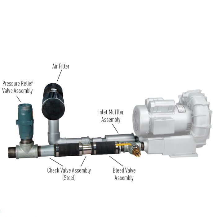
An OSHA COMPRESSED AIR SAFETY SHUT-OFF VALVES should be placed immediately after the air control shut off valve and before the hose on a compressor, and after each discharge port that a hose is connected to.
Before starting the compressor the air control valve should be closed completely. When the compressor unloads, open the air shut off control valve very slowly. Full port ball valves tend to work better than gate or butterfly type valves.
The air shut off control valve must be fully open for the OSHA COMPRESSED AIR SAFETY SHUT-OFF VALVES to work. Some portable air compressor manufacturers recommend start-up with the air control valve slightly open. In this case you may have to close the valve and reopen it slowly to the full open position, or wait for the safety shut-off valve to reset itself.
If the OSHA COMPRESSED AIR SAFETY SHUT-OFF VALVES fails to operate despite meeting all condi-tions, check the hose line for obstructions or a hose mender restricting normal air flow.
• Turn on air supply slowly (to avoid tripping OSHA safety valve). Prior to fully reaching operation conditions, the OSHA COMPRESSED AIR SAFETY SHUT-OFF VALVES should suddenly activate and stop air flow.
• If the OSHA COMPRESSED AIR SAFETY SHUT-OFF VALVE is not activated the unit should be disconnected and the lower flow range OSHA COMPRESSED AIR SAFETY SHUT-OFF VALVES should be used. This means you need to use a different valve with a lower scfm range.
• At temperatures below 40°F ensure that OSHA COMPRESSED AIR SAFETY SHUT-OFF VALVES are not subject to icy conditions which may prevent proper functioning.

Curtiss-Wright"s selection of Pressure Relief Valves comes from its outstanding product brands Farris and Target Rock. We endeavor to support the whole life cycle of a facility and continuously provide custom products and technologies. Boasting a reputation for producing high quality, durable products, our collection of Pressure Relief Valves is guaranteed to provide effective and reliable pressure relief.
While some basic components and activations in relieving pressure may differ between the specific types of relief valves, each aims to be 100% effective in keeping your equipment running safely. Our current range includes numerous valve types, from flanged to spring-loaded, threaded to wireless, pilot operated, and much more.
A pressure relief valve is a type of safety valve designed to control the pressure in a vessel. It protects the system and keeps the people operating the device safely in an overpressure event or equipment failure.
A pressure relief valve is designed to withstand a maximum allowable working pressure (MAWP). Once an overpressure event occurs in the system, the pressure relief valve detects pressure beyond its design"s specified capability. The pressure relief valve would then discharge the pressurized fluid or gas to flow from an auxiliary passage out of the system.
Below is an example of one of our pilot operated pressure relief valves in action; the cutaway demonstrates when high pressure is released from the system.
Air pressure relief valves can be applied to a variety of environments and equipment. Pressure relief valves are a safety valve used to keep equipment and the operators safe too. They"re instrumental in applications where proper pressure levels are vital for correct and safe operation. Such as oil and gas, power generation like central heating systems, and multi-phase applications in refining and chemical processing.
At Curtiss-Wright, we provide a range of different pressure relief valves based on two primary operations – spring-loaded and pilot operated. Spring-loaded valves can either be conventional spring-loaded or balanced spring-loaded.
Spring-loaded valves are programmed to open and close via a spring mechanism. They open when the pressure reaches an unacceptable level to release the material inside the vessel. It closes automatically when the pressure is released, and it returns to an average operating level. Spring-loaded safety valves rely on the closing force applied by a spring onto the main seating area. They can also be controlled in numerous ways, such as a remote, control panel, and computer program.
Pilot-operated relief valves operate by combining the primary relieving device (main valve) with self-actuated auxiliary pressure relief valves, also known as the pilot control. This pilot control dictates the opening and closing of the main valve and responds to system pressure. System pressure is fed from the inlet into and through the pilot control and ultimately into the main valve"s dome. In normal operating conditions, system pressure will prevent the main valve from opening.
The valves allow media to flow from an auxiliary passage and out of the system once absolute pressure is reached, whether it is a maximum or minimum level.
When the pressure is below the maximum amount, the pressure differential is slightly positive on the piston"s dome size, which keeps the main valve in the closed position. When system pressure rises and reaches the set point, the pilot will cut off flow to the dome, causing depressurization in the piston"s dome side. The pressure differential has reversed, and the piston will rise, opening the main valve, relieving pressure.
When the process pressure decreases to a specific pressure, the pilot closes, the dome is repressurized, and the main valve closes. The main difference between spring-loaded PRVs and pilot-operated is that a pilot-operated safety valve uses pressure to keep the valve closed.
Pilot-operated relief valves are controlled by hand and are typically opened often through a wheel or similar component. The user opens the valve when the gauge signifies that the system pressure is at an unsafe level; once the valve has opened and the pressure has been released, the operator can shut it by hand again.
Increasing pressure helps to maintain the pilot"s seal. Once the setpoint has been reached, the valve opens. This reduces leakage and fugitive emissions.
At set pressure the valve snaps to full lift. This can be quite violent on large pipes with significant pressure. The pressure has to drop below the set pressure in order for the piston to reseat.
The pilot is designed to open gradually, so that less of the system fluid is lost during each relief event. The piston lifts in proportion to the overpressure.
At Curtiss-Wright we also provide solutions for pressure relief valve monitoring. Historically, pressure relief valves have been difficult or impossible to monitor. Our SmartPRV features a 2600 Series pressure relief valve accessorized with a wireless position monitor that alerts plant operators during an overpressure event, including the time and duration.
There are many causes of overpressure, but the most common ones are typically blocked discharge in the system, gas blowby, and fire. Even proper inspection and maintenance will not eliminate the occurrence of leakages. An air pressure relief valve is the only way to ensure a safe environment for the device, its surroundings, and operators.
A PRV and PSV


 8613371530291