
psv pressure safety valve free sample

The primary purpose of a safety valve is to protect life, property and the environment. Safety valves are designed to open and release excess pressure from vessels or equipment and then close again.
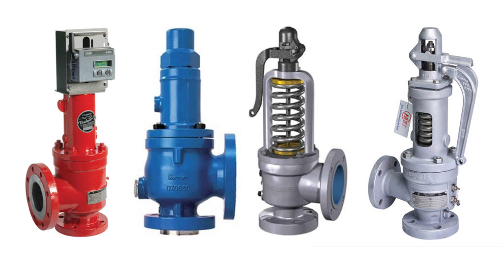
The function of safety valves differs depending on the load or main type of the valve. The main types of safety valves are spring-loaded, weight-loaded and controlled safety valves.
Regardless of the type or load, safety valves are set to a specific set pressure at which the medium is discharged in a controlled manner, thus preventing overpressure of the equipment. In dependence of several parameters such as the contained medium, the set pressure is individual for each safety application.

The primary purpose of a pressure relief valve is to protect life, property and the environment. Pressure relief valves are designed to open and release excess pressure from vessels or equipment and then close again.
The function of pressure relief valves differs depending on the main type or loading principle of the valve. The main types of pressure relief valves are spring-loaded, weight-loaded and controlled pressure relief valves.
Regardless of the type or load, pressure relief valves are set to a specific set pressure at which the medium is discharged in a controlled manner, thus preventing overpressure of the equipment. In dependence of several parameters such as the contained medium, the set pressure is individual for each safety application.

Safety valves and pressure relief valves are crucial for one main reason: safety. This means safety for the plant and equipment as well as safety for plant personnel and the surrounding environment.
Safety valves and pressure relief valves protect vessels, piping systems, and equipment from overpressure, which, if unchecked, can not only damage a system but potentially cause an explosion. Because these valves play such an important role, it’s absolutely essential that the right valve is used every time.
The valve size must correspond to the size of the inlet and discharge piping. The National Board specifies that the both the inlet piping and the discharge piping connected to the valve must be at least as large as the inlet/discharge opening on the valve itself.
The connection types are also important. For example, is the connection male or female? Flanged? All of these factors help determine which valve to use.
The set pressure of the valve must not exceed the maximum allowable working pressure (MAWP) of the boiler or other vessel. What this means is that the valve must open at or below the MAWP of the equipment. In turn, the MAWP of the equipment should be at least 10% greater than the highest expected operating pressure under normal circumstances.
Temperature affects the volume and viscosity of the gas or liquid flowing through the system. Temperature also helps determine the ideal material of construction for the valve. For example, steel valves can handle higher operating temperatures than valves made of either bronze or iron. Both the operating and the relieving temperature must be taken into account.
Back pressure, which may be constant or variable, is pressure on the outlet side of the pressure relief valve as a result of the pressure in the discharge system. It can affect the set pressure of the upstream valve and cause it to pop open repeatedly, which can damage the valve.
For installations with variable back pressure, valves should be selected so that the back pressure doesn’t exceed 10% of the valve set pressure. For installations with high levels of constant back pressure, a bellows-sealed valve or pilot-operated valve may be required.
Different types of service (steam, air, gas, etc.) require different valves. In addition, the valve material of construction needs to be appropriate for the service. For example, valves made of stainless steel are preferable for corrosive media.
Safety valves and relief valves must be able to relieve pressure at a certain capacity. The required capacity is determined by several factors including the geometry of the valve, the temperature of the media, and the relief discharge area.
These are just the basic factors that must be considered when selecting and sizing safety valves and relief valves. You must also consider the physical dimensions of the equipment and the plant, as well as other factors related to the environment in which the valve will operate.

In order to ensure that the maximum allowable accumulation pressure of any system or apparatus protected by a safety valve is never exceeded, careful consideration of the safety valve’s position in the system has to be made. As there is such a wide range of applications, there is no absolute rule as to where the valve should be positioned and therefore, every application needs to be treated separately.
A common steam application for a safety valve is to protect process equipment supplied from a pressure reducing station. Two possible arrangements are shown in Figure 9.3.3.
The safety valve can be fitted within the pressure reducing station itself, that is, before the downstream stop valve, as in Figure 9.3.3 (a), or further downstream, nearer the apparatus as in Figure 9.3.3 (b). Fitting the safety valve before the downstream stop valve has the following advantages:
• The safety valve can be tested in-line by shutting down the downstream stop valve without the chance of downstream apparatus being over pressurised, should the safety valve fail under test.
• When setting the PRV under no-load conditions, the operation of the safety valve can be observed, as this condition is most likely to cause ‘simmer’. If this should occur, the PRV pressure can be adjusted to below the safety valve reseat pressure.
Indeed, a separate safety valve may have to be fitted on the inlet to each downstream piece of apparatus, when the PRV supplies several such pieces of apparatus.
• If supplying one piece of apparatus, which has a MAWP pressure less than the PRV supply pressure, the apparatus must be fitted with a safety valve, preferably close-coupled to its steam inlet connection.
• If a PRV is supplying more than one apparatus and the MAWP of any item is less than the PRV supply pressure, either the PRV station must be fitted with a safety valve set at the lowest possible MAWP of the connected apparatus, or each item of affected apparatus must be fitted with a safety valve.
• The safety valve must be located so that the pressure cannot accumulate in the apparatus viaanother route, for example, from a separate steam line or a bypass line.
It could be argued that every installation deserves special consideration when it comes to safety, but the following applications and situations are a little unusual and worth considering:
• Fire - Any pressure vessel should be protected from overpressure in the event of fire. Although a safety valve mounted for operational protection may also offer protection under fire conditions,such cases require special consideration, which is beyond the scope of this text.
• Exothermic applications - These must be fitted with a safety valve close-coupled to the apparatus steam inlet or the body direct. No alternative applies.
• Safety valves used as warning devices - Sometimes, safety valves are fitted to systems as warning devices. They are not required to relieve fault loads but to warn of pressures increasing above normal working pressures for operational reasons only. In these instances, safety valves are set at the warning pressure and only need to be of minimum size. If there is any danger of systems fitted with such a safety valve exceeding their maximum allowable working pressure, they must be protected by additional safety valves in the usual way.
In order to illustrate the importance of the positioning of a safety valve, consider an automatic pump trap (see Block 14) used to remove condensate from a heating vessel. The automatic pump trap (APT), incorporates a mechanical type pump, which uses the motive force of steam to pump the condensate through the return system. The position of the safety valve will depend on the MAWP of the APT and its required motive inlet pressure.
This arrangement is suitable if the pump-trap motive pressure is less than 1.6 bar g (safety valve set pressure of 2 bar g less 0.3 bar blowdown and a 0.1 bar shut-off margin). Since the MAWP of both the APT and the vessel are greater than the safety valve set pressure, a single safety valve would provide suitable protection for the system.
However, if the pump-trap motive pressure had to be greater than 1.6 bar g, the APT supply would have to be taken from the high pressure side of the PRV, and reduced to a more appropriate pressure, but still less than the 4.5 bar g MAWP of the APT. The arrangement shown in Figure 9.3.5 would be suitable in this situation.
Here, two separate PRV stations are used each with its own safety valve. If the APT internals failed and steam at 4 bar g passed through the APT and into the vessel, safety valve ‘A’ would relieve this pressure and protect the vessel. Safety valve ‘B’ would not lift as the pressure in the APT is still acceptable and below its set pressure.
It should be noted that safety valve ‘A’ is positioned on the downstream side of the temperature control valve; this is done for both safety and operational reasons:
Operation - There is less chance of safety valve ‘A’ simmering during operation in this position,as the pressure is typically lower after the control valve than before it.
Also, note that if the MAWP of the pump-trap were greater than the pressure upstream of PRV ‘A’, it would be permissible to omit safety valve ‘B’ from the system, but safety valve ‘A’ must be sized to take into account the total fault flow through PRV ‘B’ as well as through PRV ‘A’.
A pharmaceutical factory has twelve jacketed pans on the same production floor, all rated with the same MAWP. Where would the safety valve be positioned?
One solution would be to install a safety valve on the inlet to each pan (Figure 9.3.6). In this instance, each safety valve would have to be sized to pass the entire load, in case the PRV failed open whilst the other eleven pans were shut down.
If additional apparatus with a lower MAWP than the pans (for example, a shell and tube heat exchanger) were to be included in the system, it would be necessary to fit an additional safety valve. This safety valve would be set to an appropriate lower set pressure and sized to pass the fault flow through the temperature control valve (see Figure 9.3.8).

A safety valve must always be sized and able to vent any source of steam so that the pressure within the protected apparatus cannot exceed the maximum allowable accumulated pressure (MAAP). This not only means that the valve has to be positioned correctly, but that it is also correctly set. The safety valve must then also be sized correctly, enabling it to pass the required amount of steam at the required pressure under all possible fault conditions.
Once the type of safety valve has been established, along with its set pressure and its position in the system, it is necessary to calculate the required discharge capacity of the valve. Once this is known, the required orifice area and nominal size can be determined using the manufacturer’s specifications.
In order to establish the maximum capacity required, the potential flow through all the relevant branches, upstream of the valve, need to be considered.
In applications where there is more than one possible flow path, the sizing of the safety valve becomes more complicated, as there may be a number of alternative methods of determining its size. Where more than one potential flow path exists, the following alternatives should be considered:
This choice is determined by the risk of two or more devices failing simultaneously. If there is the slightest chance that this may occur, the valve must be sized to allow the combined flows of the failed devices to be discharged. However, where the risk is negligible, cost advantages may dictate that the valve should only be sized on the highest fault flow. The choice of method ultimately lies with the company responsible for insuring the plant.
For example, consider the pressure vessel and automatic pump-trap (APT) system as shown in Figure 9.4.1. The unlikely situation is that both the APT and pressure reducing valve (PRV ‘A’) could fail simultaneously. The discharge capacity of safety valve ‘A’ would either be the fault load of the largest PRV, or alternatively, the combined fault load of both the APT and PRV ‘A’.
This document recommends that where multiple flow paths exist, any relevant safety valve should, at all times, be sized on the possibility that relevant upstream pressure control valves may fail simultaneously.
The supply pressure of this system (Figure 9.4.2) is limited by an upstream safety valve with a set pressure of 11.6 bar g. The fault flow through the PRV can be determined using the steam mass flow equation (Equation 3.21.2):
Once the fault load has been determined, it is usually sufficient to size the safety valve using the manufacturer’s capacity charts. A typical example of a capacity chart is shown in Figure 9.4.3. By knowing the required set pressure and discharge capacity, it is possible to select a suitable nominal size. In this example, the set pressure is 4 bar g and the fault flow is 953 kg/h. A DN32/50 safety valve is required with a capacity of 1 284 kg/h.
Where sizing charts are not available or do not cater for particular fluids or conditions, such as backpressure, high viscosity or two-phase flow, it may be necessary to calculate the minimum required orifice area. Methods for doing this are outlined in the appropriate governing standards, such as:
Coefficients of discharge are specific to any particular safety valve range and will be approved by the manufacturer. If the valve is independently approved, it is given a ‘certified coefficient of discharge’.
This figure is often derated by further multiplying it by a safety factor 0.9, to give a derated coefficient of discharge. Derated coefficient of discharge is termed Kdr= Kd x 0.9
Critical and sub-critical flow - the flow of gas or vapour through an orifice, such as the flow area of a safety valve, increases as the downstream pressure is decreased. This holds true until the critical pressure is reached, and critical flow is achieved. At this point, any further decrease in the downstream pressure will not result in any further increase in flow.
A relationship (called the critical pressure ratio) exists between the critical pressure and the actual relieving pressure, and, for gases flowing through safety valves, is shown by Equation 9.4.2.
For gases, with similar properties to an ideal gas, ‘k’ is the ratio of specific heat of constant pressure (cp) to constant volume (cv), i.e. cp : cv. ‘k’ is always greater than unity, and typically between 1 and 1.4 (see Table 9.4.8).
For steam, although ‘k’ is an isentropic coefficient, it is not actually the ratio of cp : c. As an approximation for saturated steam, ‘k’ can be taken as 1.135, and superheated steam, as 1.3. As a guide, for saturated steam, critical pressure is taken as 58% of accumulated inlet pressure in absolute terms.
Overpressure - Before sizing, the design overpressure of the valve must be established. It is not permitted to calculate the capacity of the valve at a lower overpressure than that at which the coefficient of discharge was established. It is however, permitted to use a higher overpressure (see Table 9.2.1, Module 9.2, for typical overpressure values). For DIN type full lift (Vollhub) valves, the design lift must be achieved at 5% overpressure, but for sizing purposes, an overpressure value of 10% may be used.
For liquid applications, the overpressure is 10% according to AD-Merkblatt A2, DIN 3320, TRD 421 and ASME, but for non-certified ASME valves, it is quite common for a figure of 25% to be used.
Backpressure - The sizing calculations in the AD-Merkblatt A2, DIN 3320 and TRD 421 standards account for backpressure in the outflow function,(Ψ), which includes a backpressure correction.
The ASME/API RP 520 and EN ISO 4126 standards, however, require an additional backpressure correction factor to be determined and then incorporated in the relevant equation.
Two-phase flow - When sizing safety valves for boiling liquids (e.g. hot water) consideration must be given to vaporisation (flashing) during discharge. It is assumed that the medium is in liquid state when the safety valve is closed and that, when the safety valve opens, part of the liquid vaporises due to the drop in pressure through the safety valve. The resulting flow is referred to as two-phase flow.
The required flow area has to be calculated for the liquid and vapour components of the discharged fluid. The sum of these two areas is then used to select the appropriate orifice size from the chosen valve range. (see Example 9.4.3)
Valves for industrial applicationsIn order to prevent the uncontrolled rise in pressure in pressure vessels or pressurized pipelines, a safety valve is inserted. The safety valve is designed so that it opens at a given maximum pressure, thereby relieving the line or the container. Safety valves find their use in almost all areas of the pressure vessel and pipeline construction. In cryogenics as a spring-loaded safety valve for example.

One of the most critical automatic safety devices in a pressure system is the pressure safety valve. The primary purpose of a pressure safety valve is the protection of life, property and environment during an over-pressure event in a pressurized vessel or equipment. An over-pressure event refers to any condition which would cause pressure in a vessel or system to increase beyond the specified design pressure or maximum allowable working pressure. A pressure safety valve is designed to open and relieve excess pressure from vessels or equipment and to re-close and prevent the further release of fluid after normal conditions have been restored.
It is important to ensure that the pressure safety valve is capable to operate at all times and under all circumstances. A safety valve is not a process valve or pressure regulator and should not be misused as such.
Each of the above listed events may occur individually or simultaneously. Every cause of over-pressure will create a different mass or volume flow to be discharged. For e.g. small mass flow for thermal expansion and large mass flow in case of a chemical reaction. It is the process engineers responsibility to determine the most worst case scenario for the sizing and selection of a suitable pressure safety device.
In a Spring loaded Pressure Safety Valve the closing force or spring force is applied by a helical spring which is compressed by an adjusting screw. The spring force is transferred via the spindle onto the disc. The disc seals against the nozzle as long as the spring force is larger than the force created by the pressure at the inlet of the valve. Figure 2 shows all the steps in working of Spring Loaded Pressure Safety Valves.
In an upset situation a safety valve will open at a predetermined set pressure. The spring force Fs is acting in closing direction and Fp, the force created by the pressure at the inlet of the safety valve, is acting in opening direction. At set pressure the forces Fs and Fp are balanced. There is no resulting force to keep the disc down on the seat. The safety valve will visibly or audibly start to leak (initial audible discharge).
As the pressure inside the system increases, the force Fp increase above the set pressure and the additional spring force required to further compress the spring is overcome. The valve will open rapidly with a “pop”, in most cases to its full lift.
In most applications a properly sized safety valve will decrease the pressure in the vessel when discharging. The pressure in the vessel will decrease at any subsequent point, but not later than the end of the upset situation. A decreasing pressure in the vessel will lower the force Fp. At set pressure however the flow is still acting on the enlarged disc area, which will keep the valve open. A further reduction in pressure is required until the spring force Fs is again greater than Fp and the safety valve begins to close. At the so called reseating pressure the disc will touch the nozzle again and the safety valve closes.
Pilot Operated Safety Valve is controlled by process medium. To achieve this, the system pressure is applied to the pilot valve (= control component for the main valve) via the pressure pickup. The pilot valve then uses the dome above the main valve piston to control the opening and closing of the main valve. Figure 4 shows all the steps in working of Pilot Operated Pressure Safety Valves.
During normal operation, the system pressure is picked up at the main valve inlet and routed to the dome. Since the dome area is larger than the area of the main valve seat, the closing force is greater than the opening force. This keeps the main valve tightly closed.
At set pressure, the pilot valve actuates. The medium is no longer routed to the dome. This prevents a further rise in dome pressure. Also, the dome is vented. As a result, the closing force ceases as a precondition for the system over-pressure to push the main valve open. Depending on the design of the pilot valve, this opening is either rapid and complete (Pop Action) or gradual and partial following system pressure (Modulate Action).
If system pressure drops to closing pressure, the pilot valve actuates and again routes the medium to the dome. The pressure in the dome builds up and the main valve closes either rapid and complete (Pop Action) or gradual and partial following system pressure (Modulate Action).
“Pressure Safety Valve” and “Pressure Relief Valve” are commonly used terms to identify pressure relief devices on a vessel or equipment. Although freely used interchangeably, these terms differ in the following aspect:
Pressure safety valve is the term used to describe relief device on a compressible fluid or gas filled vessel. For such a valve the opening is sudden. When the set pressure of the valve is reached, the valve opens almost fully.
Pressure relief valve is the term used to describe relief device on a liquid filled vessel. For such a valve the opening is proportional to increase in the vessel pressure. Hence the opening of valve is not sudden, but gradual if the pressure is increased gradually.

Industrial equipment often uses either safety or relief valves to prevent damaging pressure levels from building up. Though they perform similar functions, there are some critical differences between safety and relief valves. Understanding these two valves’ differences is essential for proper pressure system operation. So here we discuss the pressure safety valve vs pressure relief valve.
A pressure relief valve is a device that releases pressure from a system. The relief valve is generally immune to the effects of back pressure and must be periodically stripped down. Pressure relief valves are one the essential parts of a pressure system to prevent system failures. They are set to open at a predetermined pressure level. Each pressure system has a setpoint that is a predetermined limit. The setpoint determines when the valve will open and prevents overpressure.
Pressure relief valves are typically used in gas or liquid systems where there is a need to prevent excessive pressure from building up. When the pressure in the system reaches a certain level, the valve will open and release the pressure. Pressure relief valves are an essential safety feature in many designs and can help to prevent damage to the system or components.
PRVs are generally considered to be safe and reliable devices. However, before installing a PRV in a system, some potential disadvantages should be considered. Here are five pros and cons of pressure relief valves:
Pressure relief valves are anessential safety feature in many systems. They protect against over-pressurization by relieving excess pressure from the system. This can help to prevent severe damage or even explosions.
Pressure relief valves can help to improve the efficiency of a system. The system can operate at lower overall pressure by relieving excess pressure and saving energy.
Pressure relief valves can be used as a safety device in systems that are susceptible to overpressurization. By relieving pressure before it builds up to a dangerous level, they can help to prevent accidents and injuries.
Pressure relief valves can be a potential source of leaks. If not properly maintained, the valve may not seat properly and can allow fluids or gasses to escape.
Pressure relief valves can sometimes cause problems if they do not open or close properly. This can lead to process disruptions and may cause safety issues.
A pressure safety valve is a device used to release pressure from a system that has exceeded its design limit. This safety valve is a fail-safe device. This type of valve is typically used in systems that contain fluids or gasses under high pressure. Pressure safety valves are designed to open and release pressure when the system has exceeded its maximum pressure limit. This helps to prevent the system from rupturing or exploding.
Pressure safety valves are an essential part of many different types of systems and can help keep both people and property safe. If anyone is ever in a situation where they need to release pressure from a system, it is essential to know how to use a pressure safety valve correctly.
A pressure safety valve (PSV) is a type used to relieve a system’s pressure. PSVs are commonly used in chemical and process industries, as well as in some kinds of pressure vessels. There are both advantages and disadvantages to using a PSV. Some of the pros of using a PSV include:
A safety valve is a pressure relief device used to prevent the over-pressurization of a system. On the other hand, a relief valve is a device used to relieve pressure from a system that is already overpressurized.
The function of a pressure relief valve is to protect a system or component from excess pressure. A safety valve, on the other hand, is designed to protect from overpressurization. Both types of valves are used in various industries, but each has unique benefits and drawbacks.
Pressure relief valves are typically used in systems where a small amount of overpressure can cause damage. On the other hand, safety valves are designed for systems where overpressurization could be catastrophic. Both valves have advantages and disadvantages, so choosing the right type of valve for the specific application is essential.
Relief valves are usually set to open at a specific pressure and will close once the pressure has been relieved. Safety valves are similar in that they are also used to protect equipment from excessive pressure. However, safety valves are designed to stay open until they are manually closed. This is because safety valves are typically used in applications where it is not safe to have a closed valve, such as in a gas line.
Two types of valves are commonly used in industrial settings: relief valves and safety valves. Both of these valves serve essential functions, but they operate in different ways.
Relief valves are designed to relieve pressure build-up in a system. They open when the system pressure reaches a certain point, which allows excess pressure to be released. On the other hand, safety valves are designed to prevent accidents by preventing system pressure from getting too high. They open when the system pressure reaches a certain point, which allows excess pressure to be released before an accident can occur.
So, which valve is better? That depends on the situation. A relief valve is the better option to protect the system from pressure build-up. If anyone need to protect the system from accidents, then a safety valve is the better option
The relief valve is made to open when it reaches a specific pressure, commonly described as a “setpoint”. Setpoints shouldn’t be misinterpreted as the pressure set. A setpoint on a relief valve is set to the lowest possible pressure rating, which means it is set to the lowest system pressure before an overpressure situation is observed. The valve will open as the pressure increases to a point higher than the setpoint. The setting point is determined as pounds per square inch (PSIG) and should be within the maximum allowed operating pressure (MAWP) limits. In safety valves, the setpoint is typically placed at about 3 percent over the working pressure level, whereas relief valves are determined at 10 percent.
No, the safety valve and relief valve can not be used interchangeably. Though both valves are seal butterfly valve and used for safety purposes, they serve different functions. A safety valve relieves excess pressure that builds up in a system, while a relief valve regulates the pressure in a system.
Knowing the difference between these two types of valves is essential, as using the wrong valve for the intended purpose can potentially be dangerous. If unsure which type of valve to use, it is always best to consult with a professional.
A few key points help us understand the safety valve vs pressure relief valve. Safety valves are designed to relieve pressure in a system when it gets too high, while relief valves are designed to relieve pressure when it gets too low. Safety valves are usually set to open at a specific pressure, while relief valves are generally open at a particular vacuum. Safety valves are typically intended for one-time use, while relief valves can be used multiple times. Choose the trusted valve manufactureraccording to the specific business needs.


 8613371530291