
baso pilot safety valve free sample

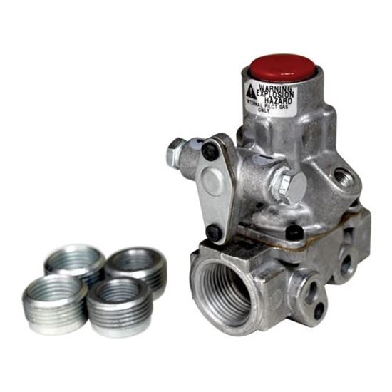
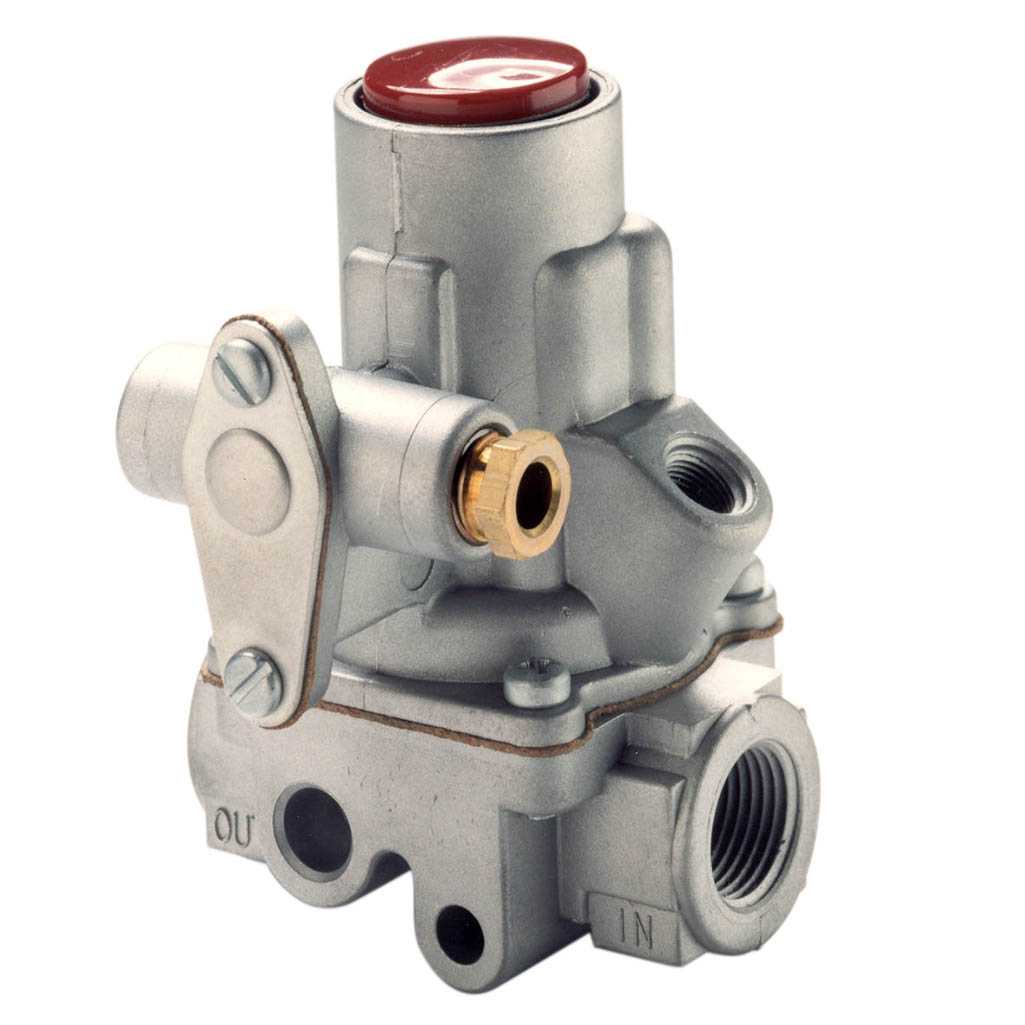
Gas Safety ValvesThese valves automatically control main gas flow. Our automatic pilot valves shut off both the main and pilot gases. Pilot gas is tapped from the main line within the control. Gas will flow only to the pilot burner when the reset button is depressed. The manual pilot valve stop can be adjusted for maximum pilot flow.
Pilot BurnersThese “J Series” combination pilot burners are universal replacement pilot burners and are supplied in three models. Mounting brackets on all four sides of each burner permit adaptation to almost any application. We also offer pilot burner fittings (R Series) and replacement flame sensors and inlet fittings (Y Series).
High pressure design allows use on gas pressures up to 25 PSI. Pilot gas is taken from within the control. Gas will pass to both pilot and main burner when reset button is depressed (H19RA 3/8" threads). Gas will not pass to the main burner equipped with flow interupter (H19LA 3/8" threads or the H19NA 1/4" threads) when reset button is depressed. Loss of signal from thermocouple shuts off both main and pilot burners. For complete specs on these Baso Valves, download the PDF below.
The first thing I will talk about is the pilot safety circuit. We need three things for combustion, air + fuel + heat. The air is supplied from the venting section, and the fuel from the gas piping section. The heat comes in the form of a pilot light, intermittent ignition device, direct spark ignition, or hot surface igniter. As I said before, in this article we will discuss standing pilot lights only.
Let’s go back and take a look at how we used to light pilots; then we’ll talk about the progression of safety devices and the state of technology today.
Development of the Standing PilotOn the old stoves, people used to turn on the gas and light the main burner with a match. As time went on, someone invented the pilot light. The pilot always stayed lit, and when the main burner was turned on, this component ignited it — nice and simple. But what happened if the pilot went out?
A small amount of gas was released to the atmosphere from the pilot burner, and when you went to light the stove, you realized the pilot was out because the stove wouldn’t light. You relit the pilot and you were set.
Now let’s apply this to a boiler. The original gas boilers had what we called wild pilots. There were two gas cocks on the old boilers, an “A” cock and a “B” cock. The “A” cock ran full size to the main gas valve and the “B” cock ran off a 1/8-in. tapping on the “A” cock. The outlet side was a 1/4-in. compression fitting.
From this fitting, 1/4-in. aluminum tubing ran to a pilot assembly. The pilot assembly sat above the main burner, and when the gas valve opened, the pilot lit the main burner. This was known as a “Wild Pilot.” There was no pilot safety control, and if the pilot went out, the main gas would still turn on when there was a call for heat.
The Safety SwitchOnce this problem was recognized, the next step was the development of the electric pilot safety switch. With this device, a thermocouple was put in the pilot flame. The flame should cover 3/8 to 1/2-in. of the thermocouple tip.
The thermocouple is a device made of two strips or wires of dissimilar materials. (See photo.) They are welded together at one end; this is called the hot junction. The pilot flame then heats the hot junction, generating a dc voltage on the other end of the two strips or wires. This is called a thermoelectric reaction.
The output of a single thermocouple is 20 to 30 millivolts dc (1,000 millivolts = 1 V). The voltage at the cold junction energizes an electromagnet, which closes a circuit on the electric pilot safety switch. The way it works is, you open the “B” cock and light the pilot. There is a button, usually red, on the pilot safety switch. You hold it down for 30 sec, which gives the thermocouple a chance to heat up and send the necessary voltage to the electromagnet to close the circuit. If the pilot goes out, the circuit opens.
This switch would get wired in series with the other safety and limit controls on the gas valve; nice and simple, no pilot, no main gas. Don’t forget, back in the old days all the gas valve was, was an electric solenoid valve.
Most valves you run into now are combination gas valves. The solenoid valve, regulator, and pilot safety are all built into one valve. On a standing pilot model we still use a thermocouple, but in a different way. The pilot valve is also built into the combination gas valve, so there’s no more “B” cock.
To light the pilot, you hold down the button on the gas valve to start the flow of gas to the pilot burner. By holding the button down, you are allowing gas into the valve and, at the same time, blocking the flow of gas to the main burner outlet port while allowing it to flow to the pilot burner through a pilot tube coming from the gas valve body. You light the pilot and hold the button down for 30 sec, and when the thermocouple sends the voltage to the gas valve, an electromagnet holds the main safety shutoff in the open position. In this position, pilot gas will always flow and main gas will flow on a call for heat. If the pilot goes out, no gas will flow into the valve.
The only difference between the pilot safety switch and the combination gas valve is that the pilot safety switch is shutting the gas off electrically, and the thermocouple in the gas valve is shutting the gas off mechanically.
Lock Out TestA properly operating safety system should lock out within 3 min of pilot outage. This test should be performed after gas pressure has been adjusted to manufacturer specifications.
Shut the gas to the appliance using the gas cock. After 3 min, turn up the thermostat to call for heat and turn on the gas; no gas should flow to the main burners or pilot burners. If gas is flowing, you must replace the gas valve. If you replace the pilot assembly, you should also do a turndown test.
It is an ANSI requirement that the pilot flame lights the main burner within 4 sec of gas reaching the main burner. This is done with the pilot gas at the minimum necessary to hold the pilot valve open.
2.Locate the pilot adjusting screw and start turning it clockwise until you notice the pilot flame start to decrease. Turn the screw one-quarter turn clockwise. Wait 1 min and turn clockwise. Keep doing this until the pilot safety circuit drops out, shutting the pilot.
4.Now turn up the thermostat to call for heat and turn the gas cock back to the “on” position. The main burners should ignite smoothly without any rollout within 4 sec. If not, relocate the pilot burner and repeat steps 1 through 4.
Let’s Go On a Service CallYou get a call from Mrs. Jones, who has no heat. You look at the boiler and find that the pilot light is out. The heating unit (boiler or furnace) has a standing pilot with a thermocouple.
The pilot will not light. Remove the pilot tube at the gas valve and depress the button. If gas is present at the gas valve and not at the pilot, check the pilot tube and pilot assembly orifice for blockages; clean or replace as necessary.
The pilot stays lit.Check the thermocouple for lint or pet hair; clean if necessary. Check the gas pressure at the inlet and outlet of the gas valve with a manometer. It should be within the parameters set by the manufacturer (which can be found on the rating plate or in the installation and operating manual). If the gas pressure is good, turn on other appliances; does pressure drop? If yes, check line sizing. If no, check the pilot flame; is it covering 3/8 to 1/2 in. of the thermocouple tip? If not, adjust. Check the condition of the draft diverter. If damaged, replace it.
If all the above items are within spec, check the thermocouple with a thermocouple tester or a millivolt meter. If the readings are not within the manufacturer’s specified range, replace the thermocouple. If it’s within the manufacturer’s specified range, replace the pilot safety unit or combination gas valve.
Note:When replacing a pilot safety unit or a combination gas valve, always replace the thermocouple. If you do not have a thermocouple tester or millivolt meter, replace the thermocouple; if the pilot still will not stay lit, replace the pilot safety unit or combination gas valve.

Flame safety is a critical aspect of any gas-fired system, but it can present puzzling choices. What equipment do you need? Which parts can be substituted? At Charles A. Hones, Inc. we use Johnson Control’ line of Baso™ safety valves and other components to tailor flame safety on Buzzer gas burners and furnaces to the user’s needs. This brief guide can help you select the right equipment for your job.
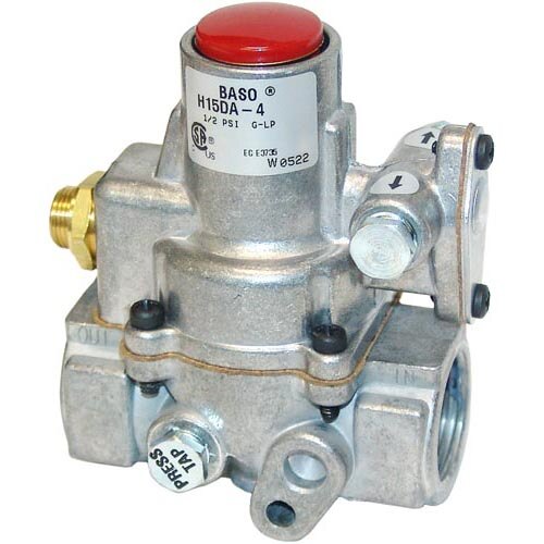
The H15 series Baso valve will provide 100% shut down of gas flow in the event of pilot failure. The H15 series valve is recommended for low pressure gas only (1/2 PSI or 14”w/c). We supply this valve in four types of sets, as follows.
This set can be used on larger pipe burners and burners such as FR-14 and multiple pipe burners that include cross flame pilots. 1” Baso set can be used on larger ring burner and discport burners (606, 606A, 312 and 313), larger 2020 Fire-Box oven furnaces and larger melters (#2700, 171A and 172). List $250.
This set is used on applications which require a stronger, more reliable pilot. This set is used on V11, V12 burners, larger pipe burners, nozzle burners, immersion burners, and application in which the pilot is subjected to reflective and/or radiant heat. This pilot set is often used when the pilot is located several inches from the main burner, such as on the outside wall of a boiler or oven. In such applications, the pilot is positioned to fire through a “pilot port” to ignite the main burner. List $361.
This set is the big brother of the set above. It is used in all of the same applications in which a rugged cast iron pilot is required. We recommend this set on the largest ring burners (V13, V14, V116A-113A), the largest discport burners (607A, 608A), and all the larger nozzle and immersion burners (VNB 250, 300, and IH 250, 300). List $431.
Note: Many Buzzer furnaces already include a #50 cast iron pilot (including the 171A, #250, #2700, ACR 60, and 185 salt bath furnace). Many Buzzer furnaces also come equipped with a redundant pilot system in which the smaller J99 style pilot ignites off the larger #50 cast iron pilot. Please call the factory if you have any questions. Additionally, parts can be substituted. For example, for an IH300 straight style complete with solenoid valves, gas cocks, and pressure gauges, you will need to replace the 60” thermocouple with a 72” thermocouple. This would add $16.00 to the cost. Please refer to the parts price list or call the Hones factory to assist in such modifications.


 8613371530291