
nozzle reaction safety valve made in china
Vatac Flanged Bronze Safety valve is a high capacity and used for boilers, piping lines and vessel protection. Designed and engineered for heavy-duty industrial use. ASME approved and National Board flow-rated for capacity. » Manufactured under ISO 9001:2008 Management...
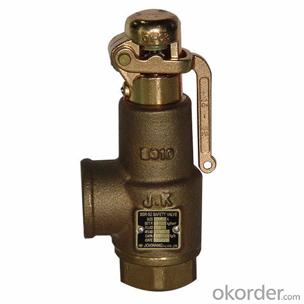
Vatac Thread Bronze Safety valve is a high capacity and used for boilers, piping lines and vessel protection. Designed and engineered for heavy-duty industrial use. ASME approved and National Board flow-rated for capacity. » Manufactured under ISO 9001:2008 Management System,...
We"re professional bronze safety valve manufacturers and suppliers in China, supplying the best industrial valves. Feel free to buy high quality bronze safety valve made in China here from our factory.

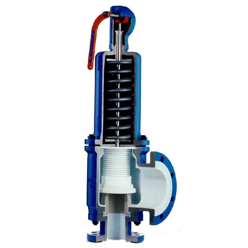
NSV Spring Loaded Safety valve is a valve that act as a protection of equipment from exploding or damaging and it is mainly installed in pressure vessels such as chemical plants, electric power boilers and gas storage tanks.
Safety Valve is a type of valve that automatically actuates when the pressure of inlet side of the valve increases to a predetermined pressure, to open the valve disc and discharge the fluid (steam or gas ) ; and when the pressure decreases to the prescribed value, to close the valve disc again. Safety valve is so-called a final safety device which controls the pressure and discharges certain amount of fluid by itself without any electric power support.

Description: The spring type double safety valve is suitable for equipment and pipelines of steam, water and other media with working temperature ≤350 °C. As an overpressure protection device. Specification: Model: A37H, A38Y, A43H Size: DN50~DN150 Pressure: PN16~PN40...
Description: This valve is suitable for use as an overpressure protection device for equipment and pipelines with a working temperature of 300 °C for air, steam, petroleum gas and other media. When the pressure in the equipment and pipeline exceeds the allowable value, the...
Pressure Safety Valve Specification: Feature: Spring loaded Connection: Flanged Body Material: A216 WCB Size: DN32~300mm (1 1/4"~12") Pressure: 150Lb-2500Lb Design Manufacture: API 520, API 526 Pressure-Temperature Ratings: ASME B16.34 Face to Face Dimension: API...
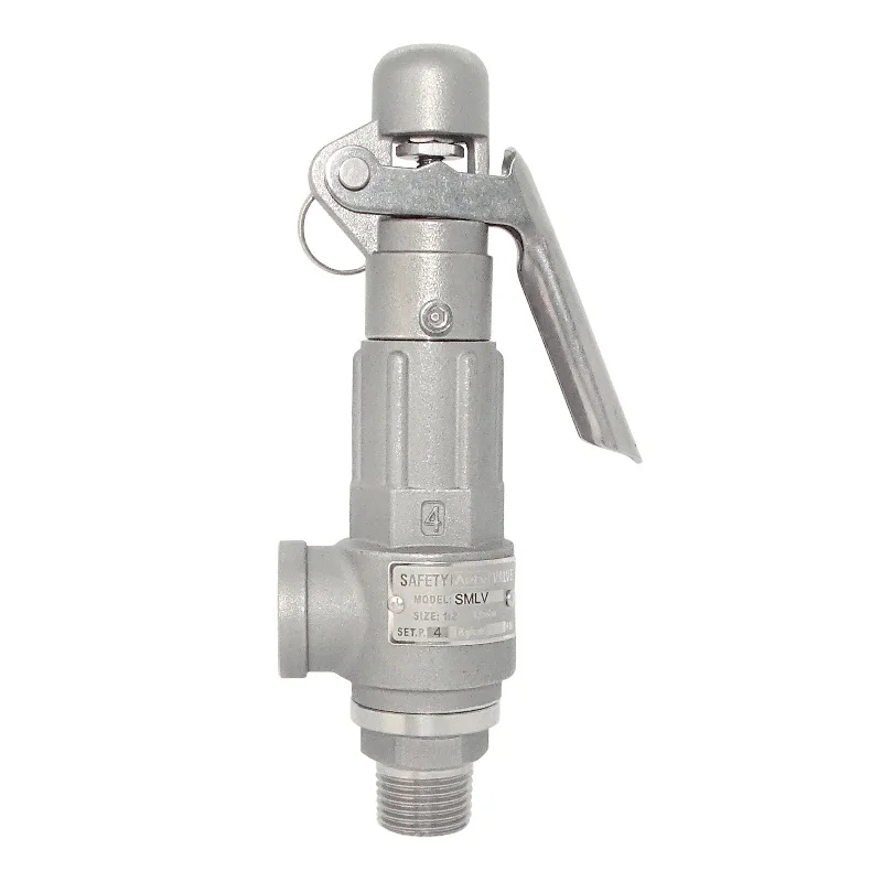
Product Description This type at a working temperture less than 450c, and are used for the equipment and pipeliness with such media as air,petroleum gas and N2-H2 mixed gas as an overpressure protection device. Specification: Name: Flange Type Stainless Steel Safety Valve for...
Our main products ball valve, butterfly valve, gate valve, globe valve, check valve, plug valve, other valve components and parts, pipe and fittings as well, with working pressure varying from Class 150Lb~2500Lb,PN6~PN420, the size from NPS1/4”~80”,DN6~DN2000, materials castings WCB

Because of different of drive source, SSV can dividedinto Hydraulic safety valve and pneumatic valve ; With thermal and high voltage explosion-proof device ; Actuators and prepare two parts of the valve, standard interface, easy replacement and maintenance .
This valve is used for power plant boilers, pressure containers, pressure and temperature reducing device and other facilities. It serves to prevent the pressure exceeding the highest allowable pres-sure value and ensure the safety of the device when working.
(1)The pressure of the disc is balanced through the lever and heavy hammer and the valve is ensured seal by moving the for ton of heavy hammer and changing the weight of heavy hammer to reach the required set pressure.
(3)At the top of valve is equipped an electromagnet to open and another to close the valve. The actions of the mechanism and the electric appliance are separate and will not affect each other.
(2)Impulse safety valve shall be installed vertically and the lever shall be kept level. The clearance from the lever to both sides of guide fork shall be even.
(4)A long distance between the leading pipe of the impulse safety valve and the inlet pipe of the main safety valve shall be kept. And the distance between the electric contact pressure meter and the inlet pipe of the main safety valve shall be no less than 5 times of the diameter of the inlet pipe, for feat that the validity of the mater and the impulse safety valve may be affected by the steam releasing process of the main safety valve.
This valve is used for power plant boilers, pressure containers, pressure and temperature reducing device and other facilities. It serves to present the pressure exceeding the highest allowable pres-sure value and ensure the safety of the device when working.
1,When the medium pressure rises to the set pressure, the in-pulse safety valve opens, and the medium in the impulse pipe enters into the piston chamber of the main safety valve from impulse pipe, forcing the piston to descend, and then the valve automatically open-s; when the impulse safety valve closes, the disc will slash automatically close.
2,The main safety valve shall be fastened upon the gallows, which sustains the back-seat force produced in the steam discharging process of the main safety valve.
3,The exhaust pipe shall contain a special gallows to prevent the force of its weight directly applying on the main safety valve. The connecting Lange At the lowest point of the exhaust pipe, water drainage shall be taken into consideration to avoid producing water hammer while discharging set between the main safety valve and exhaust pipe shall eliminate any extra stress.

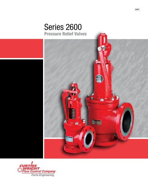
With Farris, a trustworthy valve is only part of our promise. Farris provides customers with total pressure relief management solutions that support a facility’s entire lifecycle, transforming the way you ensure plant safety:
Now you can accurately size and select a pressure relief valves for any combination of process applications with SizeMaster™ Mark IV pressure relief valve engineering software. This program for Windows® (all versions) brings unprecedented integration of standard engineering practice to the task of sizing and selecting pressure relief valves.
With SizeMaster Mark IV software, you can define as few as one or as many as 64 different sizing scenarios including blocked flow, fire, thermal and tube rupture, from a scenario matrix grid. Selection of the pressure relief valve is automatically based on the relief area of the worst case scenario. Various Wizards make the most complicated task simple; for instance, the Capacity Wizard allows you to determine accurate vapor generation for vessels of all types.
Quicksize Database Tube Rupture Scenario English/Metric Dimensional Drawings API-Omega 2-phase flow calculations Noise and reaction force calculations Multiple valve sizing Standard Windows user interface functions Developed under ISO 9001-2000 guidelines Supports network database access Database administration tools Interactive product catalog Internal client/project database Complete revision control with definable database access English/metric units definable by job level Import/export capabilities Online help including a variety of tutorials
The engineering worksheet engine also checks your parameters and all intermediate calculations against the standards’ constraints, and it tells you about any non-compliance that it encounters, such as attempting to size a conventional valve when a bellows valve is required.
Once SizeMaster calculates the orifice area required to relieve your process scenarios, SizeMaster guides you through the selection of the appropriate Farris pressure relief valve and its materials and other options.
SizeMaster includes catalogue information for Farris 2600, 2700, 3800, 6400, 6600, 4200, 2800 , and 7200 series pressure relief valves, including their black and white drawings. While you are selecting a Farris type number for a tag, SizeMaster ensures that you don’t pick a valve that is not applicable to your process parameters (such as a liquid-service valve for a vapor scenario), and on-line help is available to assist in the determination of each of the digits of the Farris type number, based on your process scenarios.
From its Quick Size and Capacity Wizards through to its consistently standard Windows user interface, SizeMaster makes the job of sizing and selecting pressure relief valves easy, and its worksheet management and workflow auditing facilities let you ensure that your results are correct.

Throughout the years, HZVALVE has developed its Quality System which is an integral part of our manufacturing policy. Our primary goal is to provide products that meet and exceed market standards. In this sense, HZVALVE is an ISO-9001 Audited and Certified Company that has achieved major certifications worldwide. Our system consists of a rigorous quality control as well as the selection of raw materials from approved vendors. Control over our manufacturing process is vital. Serial numbers allow HZVALVE to monitor and trace fabrication processes along with the materials of components.
HZVALVE owned independent quality department with over 25 experienced inspectors. Our target is to cover all vital point including material, procession, assembling, testing and package for overall quality controlling and supervision. We keep the understanding that the high quality products create more value to customers.

As soon as mankind was able to boil water to create steam, the necessity of the safety device became evident. As long as 2000 years ago, the Chinese were using cauldrons with hinged lids to allow (relatively) safer production of steam. At the beginning of the 14th century, chemists used conical plugs and later, compressed springs to act as safety devices on pressurised vessels.
Early in the 19th century, boiler explosions on ships and locomotives frequently resulted from faulty safety devices, which led to the development of the first safety relief valves.
In 1848, Charles Retchie invented the accumulation chamber, which increases the compression surface within the safety valve allowing it to open rapidly within a narrow overpressure margin.
Today, most steam users are compelled by local health and safety regulations to ensure that their plant and processes incorporate safety devices and precautions, which ensure that dangerous conditions are prevented.
The principle type of device used to prevent overpressure in plant is the safety or safety relief valve. The safety valve operates by releasing a volume of fluid from within the plant when a predetermined maximum pressure is reached, thereby reducing the excess pressure in a safe manner. As the safety valve may be the only remaining device to prevent catastrophic failure under overpressure conditions, it is important that any such device is capable of operating at all times and under all possible conditions.
Safety valves should be installed wherever the maximum allowable working pressure (MAWP) of a system or pressure-containing vessel is likely to be exceeded. In steam systems, safety valves are typically used for boiler overpressure protection and other applications such as downstream of pressure reducing controls. Although their primary role is for safety, safety valves are also used in process operations to prevent product damage due to excess pressure. Pressure excess can be generated in a number of different situations, including:
The terms ‘safety valve’ and ‘safety relief valve’ are generic terms to describe many varieties of pressure relief devices that are designed to prevent excessive internal fluid pressure build-up. A wide range of different valves is available for many different applications and performance criteria.
In most national standards, specific definitions are given for the terms associated with safety and safety relief valves. There are several notable differences between the terminology used in the USA and Europe. One of the most important differences is that a valve referred to as a ‘safety valve’ in Europe is referred to as a ‘safety relief valve’ or ‘pressure relief valve’ in the USA. In addition, the term ‘safety valve’ in the USA generally refers specifically to the full-lift type of safety valve used in Europe.
Pressure relief valve- A spring-loaded pressure relief valve which is designed to open to relieve excess pressure and to reclose and prevent the further flow of fluid after normal conditions have been restored. It is characterised by a rapid-opening ‘pop’ action or by opening in a manner generally proportional to the increase in pressure over the opening pressure. It may be used for either compressible or incompressible fluids, depending on design, adjustment, or application.
Safety valves are primarily used with compressible gases and in particular for steam and air services. However, they can also be used for process type applications where they may be needed to protect the plant or to prevent spoilage of the product being processed.
Relief valve - A pressure relief device actuated by inlet static pressure having a gradual lift generally proportional to the increase in pressure over opening pressure.
Relief valves are commonly used in liquid systems, especially for lower capacities and thermal expansion duty. They can also be used on pumped systems as pressure overspill devices.
Safety relief valve - A pressure relief valve characterised by rapid opening or pop action, or by opening in proportion to the increase in pressure over the opening pressure, depending on the application, and which may be used either for liquid or compressible fluid.
In general, the safety relief valve will perform as a safety valve when used in a compressible gas system, but it will open in proportion to the overpressure when used in liquid systems, as would a relief valve.
Safety valve- A valve which automatically, without the assistance of any energy other than that of the fluid concerned, discharges a quantity of the fluid so as to prevent a predetermined safe pressure being exceeded, and which is designed to re-close and prevent further flow of fluid after normal pressure conditions of service have been restored.
There is a wide range of safety valves available to meet the many different applications and performance criteria demanded by different industries. Furthermore, national standards define many varying types of safety valve.
The ASME standard I and ASME standard VIII for boiler and pressure vessel applications and the ASME/ANSI PTC 25.3 standard for safety valves and relief valves provide the following definition. These standards set performance characteristics as well as defining the different types of safety valves that are used:
ASME I valve - A safety relief valve conforming to the requirements of Section I of the ASME pressure vessel code for boiler applications which will open within 3% overpressure and close within 4%. It will usually feature two blowdown rings, and is identified by a National Board ‘V’ stamp.
ASME VIII valve- A safety relief valve conforming to the requirements of Section VIII of the ASME pressure vessel code for pressure vessel applications which will open within 10% overpressure and close within 7%. Identified by a National Board ‘UV’ stamp.
Full bore safety valve - A safety valve having no protrusions in the bore, and wherein the valve lifts to an extent sufficient for the minimum area at any section, at or below the seat, to become the controlling orifice.
Conventional safety relief valve -The spring housing is vented to the discharge side, hence operational characteristics are directly affected by changes in the backpressure to the valve.
Balanced safety relief valve -A balanced valve incorporates a means of minimising the effect of backpressure on the operational characteristics of the valve.
Pilot operated pressure relief valve -The major relieving device is combined with, and is controlled by, a self-actuated auxiliary pressure relief device.
Power-actuated safety relief valve - A pressure relief valve in which the major pressure relieving device is combined with, and controlled by, a device requiring an external source of energy.
Standard safety valve - A valve which, following opening, reaches the degree of lift necessary for the mass flowrate to be discharged within a pressure rise of not more than 10%. (The valve is characterised by a pop type action and is sometimes known as high lift).
Full lift (Vollhub) safety valve -A safety valve which, after commencement of lift, opens rapidly within a 5% pressure rise up to the full lift as limited by the design. The amount of lift up to the rapid opening (proportional range) shall not be more than 20%.
Direct loaded safety valve -A safety valve in which the opening force underneath the valve disc is opposed by a closing force such as a spring or a weight.
Proportional safety valve - A safety valve which opens more or less steadily in relation to the increase in pressure. Sudden opening within a 10% lift range will not occur without pressure increase. Following opening within a pressure of not more than 10%, these safety valves achieve the lift necessary for the mass flow to be discharged.
Diaphragm safety valve -A direct loaded safety valve wherein linear moving and rotating elements and springs are protected against the effects of the fluid by a diaphragm
Bellows safety valve - A direct loaded safety valve wherein sliding and (partially or fully) rotating elements and springs are protected against the effects of the fluids by a bellows. The bellows may be of such a design that it compensates for influences of backpressure.
Controlled safety valve - Consists of a main valve and a control device. It also includes direct acting safety valves with supplementary loading in which, until the set pressure is reached, an additional force increases the closing force.
Safety valve - A safety valve which automatically, without the assistance of any energy other than that of the fluid concerned, discharges a quantity of the fluid so as to prevent a predetermined safe pressure being exceeded, and which is designed to re-close and prevent further flow of fluid after normal pressure conditions of service have been restored. Note; the valve can be characterised either by pop action (rapid opening) or by opening in proportion (not necessarily linear) to the increase in pressure over the set pressure.
Direct loaded safety valve -A safety valve in which the loading due to the fluid pressure underneath the valve disc is opposed only by a direct mechanical loading device such as a weight, lever and weight, or a spring.
Assisted safety valve -A safety valve which by means of a powered assistance mechanism, may additionally be lifted at a pressure lower than the set pressure and will, even in the event of a failure of the assistance mechanism, comply with all the requirements for safety valves given in the standard.
Supplementary loaded safety valve - A safety valve that has, until the pressure at the inlet to the safety valve reaches the set pressure, an additional force, which increases the sealing force.
Note; this additional force (supplementary load), which may be provided by means of an extraneous power source, is reliably released when the pressure at the inlet of the safety valve reaches the set pressure. The amount of supplementary loading is so arranged that if such supplementary loading is not released, the safety valve will attain its certified discharge capacity at a pressure not greater than 1.1 times the maximum allowable pressure of the equipment to be protected.
Pilot operated safety valve -A safety valve, the operation of which is initiated and controlled by the fluid discharged from a pilot valve, which is itself, a direct loaded safety valve subject to the requirement of the standard.
The common characteristic shared between the definitions of conventional safety valves in the different standards, is that their operational characteristics are affected by any backpressure in the discharge system. It is important to note that the total backpressure is generated from two components; superimposed backpressure and the built-up backpressure:
Subsequently, in a conventional safety valve, only the superimposed backpressure will affect the opening characteristic and set value, but the combined backpressure will alter the blowdown characteristic and re-seat value.
The ASME/ANSI standard makes the further classification that conventional valves have a spring housing that is vented to the discharge side of the valve. If the spring housing is vented to the atmosphere, any superimposed backpressure will still affect the operational characteristics. Thiscan be seen from Figure 9.2.1, which shows schematic diagrams of valves whose spring housings are vented to the discharge side of the valve and to the atmosphere.
By considering the forces acting on the disc (with area AD), it can be seen that the required opening force (equivalent to the product of inlet pressure (PV) and the nozzle area (AN)) is the sum of the spring force (FS) and the force due to the backpressure (PB) acting on the top and bottom of the disc. In the case of a spring housing vented to the discharge side of the valve (an ASME conventional safety relief valve, see Figure 9.2.1 (a)), the required opening force is:
In both cases, if a significant superimposed backpressure exists, its effects on the set pressure need to be considered when designing a safety valve system.
Once the valve starts to open, the effects of built-up backpressure also have to be taken into account. For a conventional safety valve with the spring housing vented to the discharge side of the valve, see Figure 9.2.1 (a), the effect of built-up backpressure can be determined by considering Equation 9.2.1 and by noting that once the valve starts to open, the inlet pressure is the sum of the set pressure, PS, and the overpressure, PO.
Balanced safety valves are those that incorporate a means of eliminating the effects of backpressure. There are two basic designs that can be used to achieve this:
Although there are several variations of the piston valve, they generally consist of a piston type disc whose movement is constrained by a vented guide. The area of the top face of the piston, AP, and the nozzle seat area, AN, are designed to be equal. This means that the effective area of both the top and bottom surfaces of the disc exposed to the backpressure are equal, and therefore any additional forces are balanced. In addition, the spring bonnet is vented such that the top face of the piston is subjected to atmospheric pressure, as shown in Figure 9.2.2.
The bellows arrangement prevents backpressure acting on the upper side of the disc within the area of the bellows. The disc area extending beyond the bellows and the opposing disc area are equal, and so the forces acting on the disc are balanced, and the backpressure has little effect on the valve opening pressure.
Bellows failure is an important concern when using a bellows balanced safety valve, as this may affect the set pressure and capacity of the valve. It is important, therefore, that there is some mechanism for detecting any uncharacteristic fluid flow through the bellows vents. In addition, some bellows balanced safety valves include an auxiliary piston that is used to overcome the effects of backpressure in the case of bellows failure. This type of safety valve is usually only used on critical applications in the oil and petrochemical industries.
Since balanced pressure relief valves are typically more expensive than their unbalanced counterparts, they are commonly only used where high pressure manifolds are unavoidable, or in critical applications where a very precise set pressure or blowdown is required.
This type of safety valve uses the flowing medium itself, through a pilot valve, to apply the closing force on the safety valve disc. The pilot valve is itself a small safety valve.
The diaphragm type is typically only available for low pressure applications and it produces a proportional type action, characteristic of relief valves used in liquid systems. They are therefore of little use in steam systems, consequently, they will not be considered in this text.
The piston type valve consists of a main valve, which uses a piston shaped closing device (or obturator), and an external pilot valve. Figure 9.2.4 shows a diagram of a typical piston type, pilot operated safety valve.
The piston and seating arrangement incorporated in the main valve is designed so that the bottom area of the piston, exposed to the inlet fluid, is less than the area of the top of the piston. As both ends of the piston are exposed to the fluid at the same pressure, this means that under normal system operating conditions, the closing force, resulting from the larger top area, is greater than the inlet force. The resultant downward force therefore holds the piston firmly on its seat.
If the inlet pressure were to rise, the net closing force on the piston also increases, ensuring that a tight shut-off is continually maintained. However, when the inlet pressure reaches the set pressure, the pilot valve will pop open to release the fluid pressure above the piston. With much less fluid pressure acting on the upper surface of the piston, the inlet pressure generates a net upwards force and the piston will leave its seat. This causes the main valve to pop open, allowing the process fluid to be discharged.
When the inlet pressure has been sufficiently reduced, the pilot valve will reclose, preventing the further release of fluid from the top of the piston, thereby re-establishing the net downward force, and causing the piston to reseat.
Pilot operated safety valves offer good overpressure and blowdown performance (a blowdown of 2% is attainable). For this reason, they are used where a narrow margin is required between the set pressure and the system operating pressure. Pilot operated valves are also available in much larger sizes, making them the preferred type of safety valve for larger capacities.
One of the main concerns with pilot operated safety valves is that the small bore, pilot connecting pipes are susceptible to blockage by foreign matter, or due to the collection of condensate in these pipes. This can lead to the failure of the valve, either in the open or closed position, depending on where the blockage occurs.
The terms full lift, high lift and low lift refer to the amount of travel the disc undergoes as it moves from its closed position to the position required to produce the certified discharge capacity, and how this affects the discharge capacity of the valve.
A full lift safety valve is one in which the disc lifts sufficiently, so that the curtain area no longer influences the discharge area. The discharge area, and therefore the capacity of the valve are subsequently determined by the bore area. This occurs when the disc lifts a distance of at least a quarter of the bore diameter. A full lift conventional safety valve is often the best choice for general steam applications.
The disc of a high lift safety valve lifts a distance of at least 1/12th of the bore diameter. This means that the curtain area, and ultimately the position of the disc, determines the discharge area. The discharge capacities of high lift valves tend to be significantly lower than those of full lift valves, and for a given discharge capacity, it is usually possible to select a full lift valve that has a nominal size several times smaller than a corresponding high lift valve, which usually incurs cost advantages.Furthermore, high lift valves tend to be used on compressible fluids where their action is more proportional.
In low lift valves, the disc only lifts a distance of 1/24th of the bore diameter. The discharge area is determined entirely by the position of the disc, and since the disc only lifts a small amount, the capacities tend to be much lower than those of full or high lift valves.
Except when safety valves are discharging, the only parts that are wetted by the process fluid are the inlet tract (nozzle) and the disc. Since safety valves operate infrequently under normal conditions, all other components can be manufactured from standard materials for most applications. There are however several exceptions, in which case, special materials have to be used, these include:
Cast steel -Commonly used on higher pressure valves (up to 40 bar g). Process type valves are usually made from a cast steel body with an austenitic full nozzle type construction.
For all safety valves, it is important that moving parts, particularly the spindle and guides are made from materials that will not easily degrade or corrode. As seats and discs are constantly in contact with the process fluid, they must be able to resist the effects of erosion and corrosion.
For process applications, austenitic stainless steel is commonly used for seats and discs; sometimes they are ‘stellite faced’ for increased durability. For extremely corrosive fluids, nozzles, discs and seats are made from special alloys such as ‘monel’ or ‘hastelloy’.
The spring is a critical element of the safety valve and must provide reliable performance within the required parameters. Standard safety valves will typically use carbon steel for moderate temperatures. Tungsten steel is used for higher temperature, non-corrosive applications, and stainless steel is used for corrosive or clean steam duty. For sour gas and high temperature applications, often special materials such as monel, hastelloy and ‘inconel’ are used.
Standard safety valves are generally fitted with an easing lever, which enables the valve to be lifted manually in order to ensure that it is operational at pressures in excess of 75% of set pressure. This is usually done as part of routine safety checks, or during maintenance to prevent seizing. The fitting of a lever is usually a requirement of national standards and insurance companies for steam and hot water applications. For example, the ASME Boiler and Pressure Vessel Code states that pressure relief valves must be fitted with a lever if they are to be used on air, water over 60°C, and steam.
A test gag (Figure 9.2.7) may be used to prevent the valve from opening at the set pressure during hydraulic testing when commissioning a system. Once tested, the gag screw is removed and replaced with a short blanking plug before the valve is placed in service.
The amount of fluid depends on the particular design of safety valve. If emission of this fluid into the atmosphere is acceptable, the spring housing may be vented to the atmosphere – an open bonnet. This is usually advantageous when the safety valve is used on high temperature fluids or for boiler applications as, otherwise, high temperatures can relax the spring, altering the set pressure of the valve. However, using an open bonnet exposes the valve spring and internals to environmental conditions, which can lead to damage and corrosion of the spring.
When the fluid must be completely contained by the safety valve (and the discharge system), it is necessary to use a closed bonnet, which is not vented to the atmosphere. This type of spring enclosure is almost universally used for small screwed valves and, it is becoming increasingly common on many valve ranges since, particularly on steam, discharge of the fluid could be hazardous to personnel.
Some safety valves, most commonly those used for water applications, incorporate a flexible diaphragm or bellows to isolate the safety valve spring and upper chamber from the process fluid, (see Figure 9.2.9).

We always get the job done to be a tangible staff to ensure that we can easily offer you the best high-quality and the greatest value for Wedge Gate Valve, Gate Valve, Double Flanged Dual Plate Check Valve.Faced with economic globalization, we are determined to become a leader in the Safety Relief Valve industry and surpass ourselves. We sincerely hope to cooperate with you, share success together, and forge ahead firmly to a more brilliant future. We have a group of highly educated, skilled and technically proficient service team and strict quality management system. We are equipped with professional R&D team, design team and engineering team to provide comprehensive after-sales guarantee for our customers. Our company has complete equipment, complete and scientific quality management system. We adhere to the quality policy of people-oriented, integrity and customer satisfaction. We will take a serious and responsible attitude towards the friendly cooperation with foreign customers and peers. Innovation is the soul of improving the competitiveness of an enterprise. This includes product innovation and management innovation. Product innovation can continuously improve the value content and competitiveness of products, and management innovation can ensure that enterprises are more efficient.
We are adhering to the concept of ethics, honesty, pursuit of excellence, and win-win cooperation, and we are willing to work together with colleagues from all walks of life to write a brilliant chapter in the field of Globe Valve, Pneumatic Air Control Valve, Fully Lugged Butterfly Valve! We"re well-known as one of the leading Safety Relief Valve manufacturers and suppliers in China. Please feel free to wholesale high quality Safety Relief Valve for sale here from our factory. Good service and punctual delivery are available.
The 2900/2900 TM Series Gen II is a full-nozzle pilot-operated safety relief valve (POSRV) matching API 526 direct-spring PRV dimensions. Its patented full-nozzle integral sense design allows for easy maintenance as well as simple spring-loaded to pilot-operated PRV conversions throughout the lifecycle of the valve. The 2900 Triple Media (TM) Series is the first full nozzle POSRV engineered to perform on liquid, air/gas, and steam media and is multi-media certified to meet multiple media capacity stamping per ASME B & PVC Code Case 2787. Both valve series use the same pilot valve technology as the 3900 Series including the ‘True Zero Leakage’ modulating pilot, providing a modernized overpressure protection solution for reducing carbon footprint and emissions.


 8613371530291